 Tobias Rathje
I decided to use an ATmega162 for the clock as I allready had a couple of those lying around. They were originally bought for another project many years ago. ATmega162 differs from ATmega16 mainly in having two UART's. First I only needed one UART for debugging purposes, but later it turned out that having two UART's was actually necessary.
In another junk pile I found an unused breadboard PCB with suitable dimensions for the project.
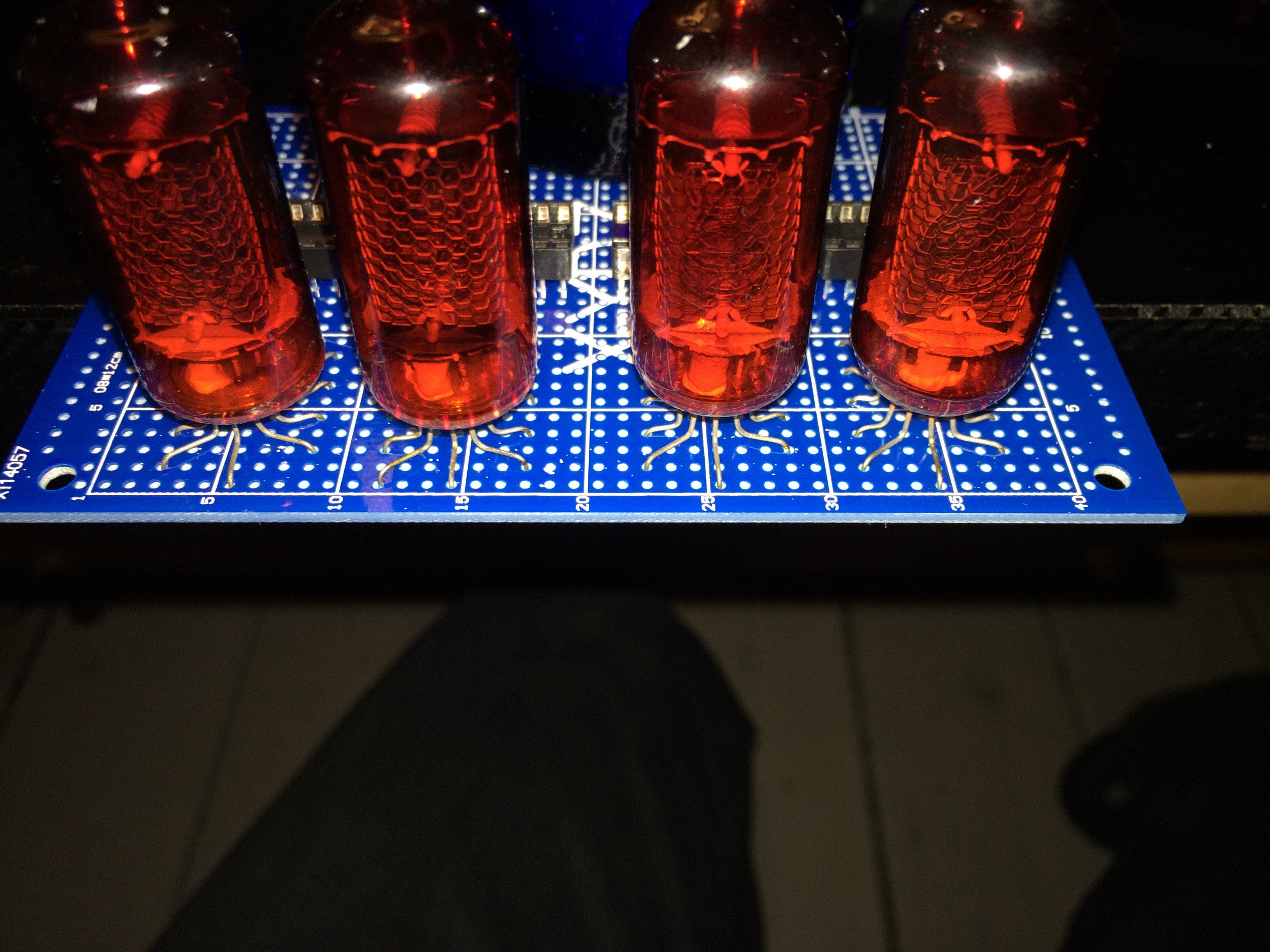
Test mounting of the tubes:
Initial layout of the board:
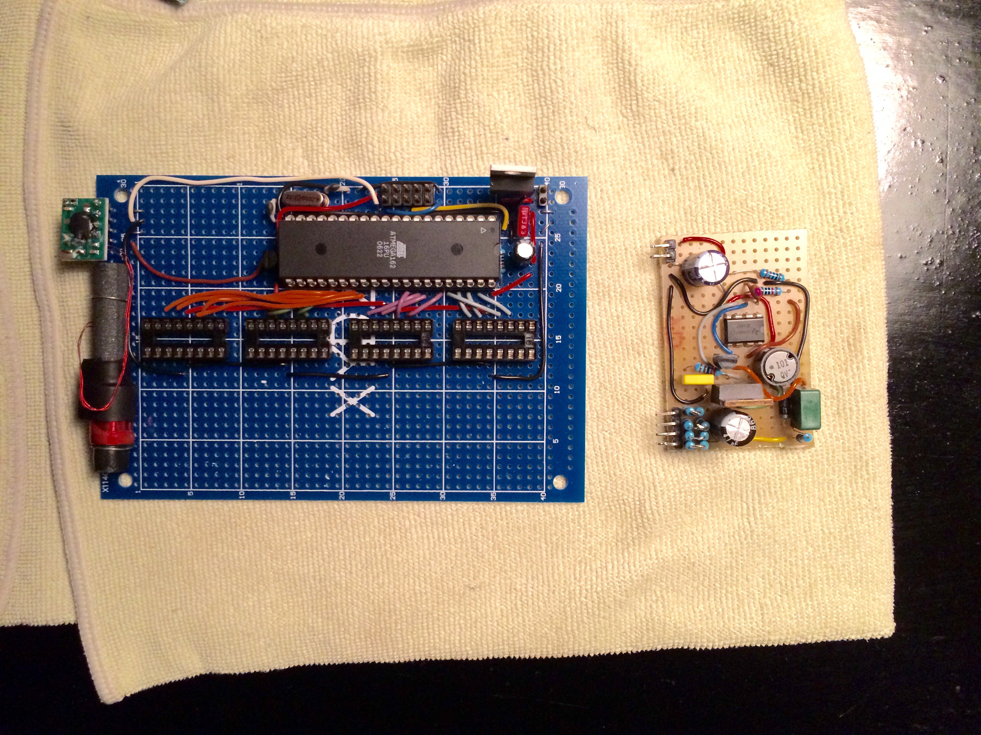
Voltage regulator, MCU and sockets for the nixie drivers mounted. The DCF-77 receiver I first planned to use for time sync on the left, my crude HV PSU on the right.
Discussions
Become a Hackaday.io Member
Create an account to leave a comment. Already have an account? Log In.