MCU for closed loop control
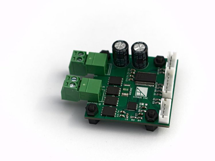
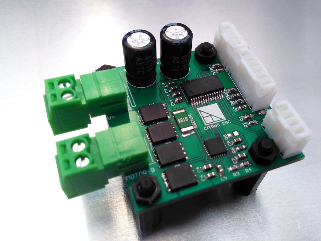
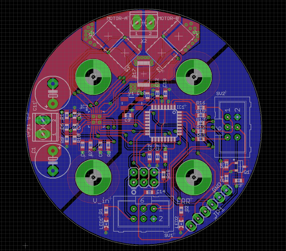
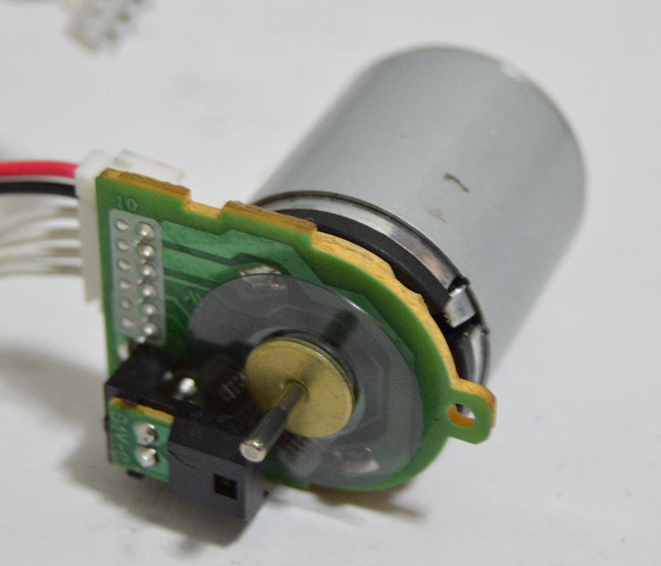
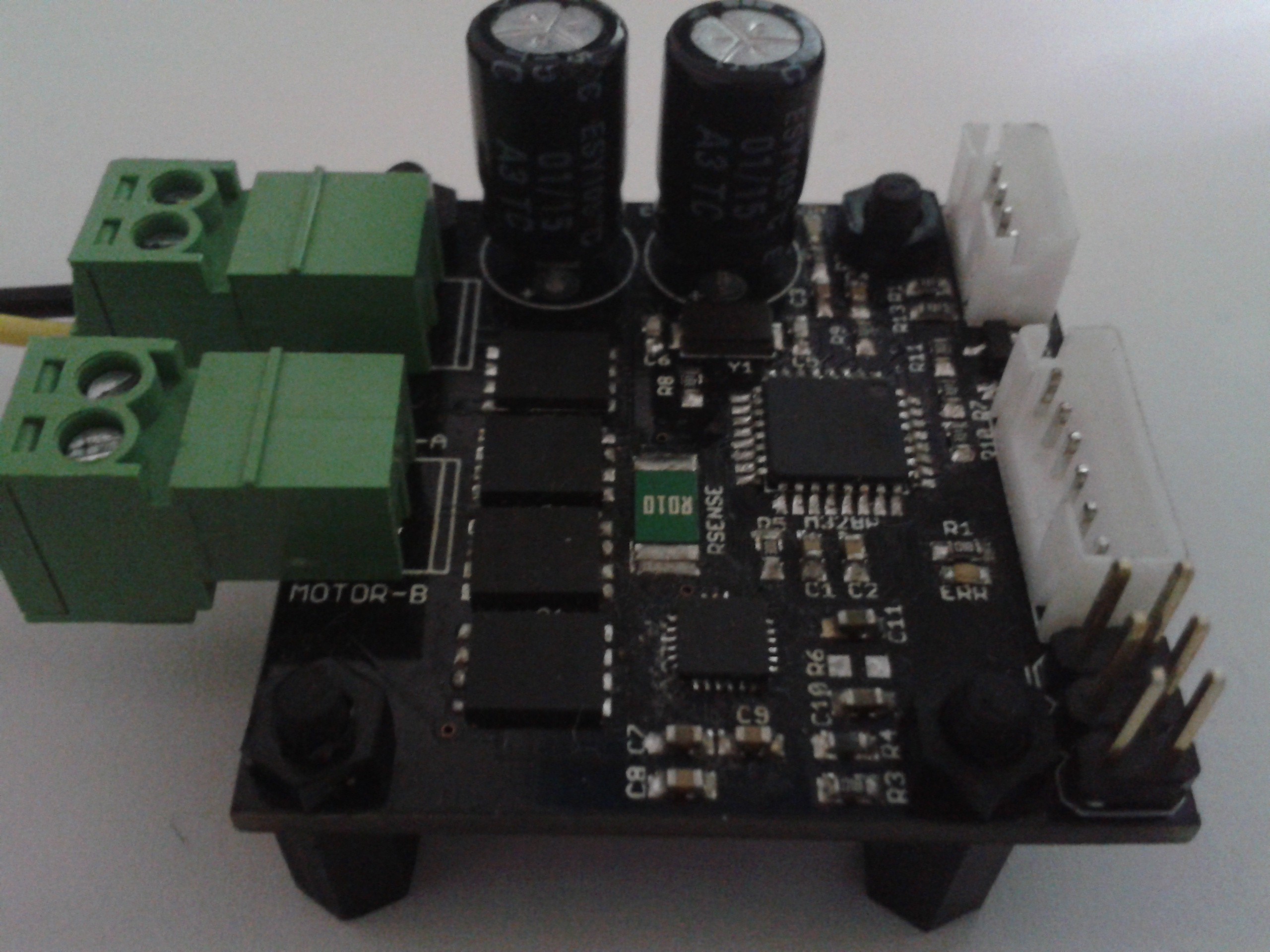
An ATmega328 microcontroller operating at 20 MHz is present to read the STEP/DIR signals from the machine controller, read a quadrature encoder input and perform the calculations required for PID control of the motor position.
It also controls an indicator LED for signaling the different fault modes the device is able to detect, such as motor overcurrent and driver undervoltage.
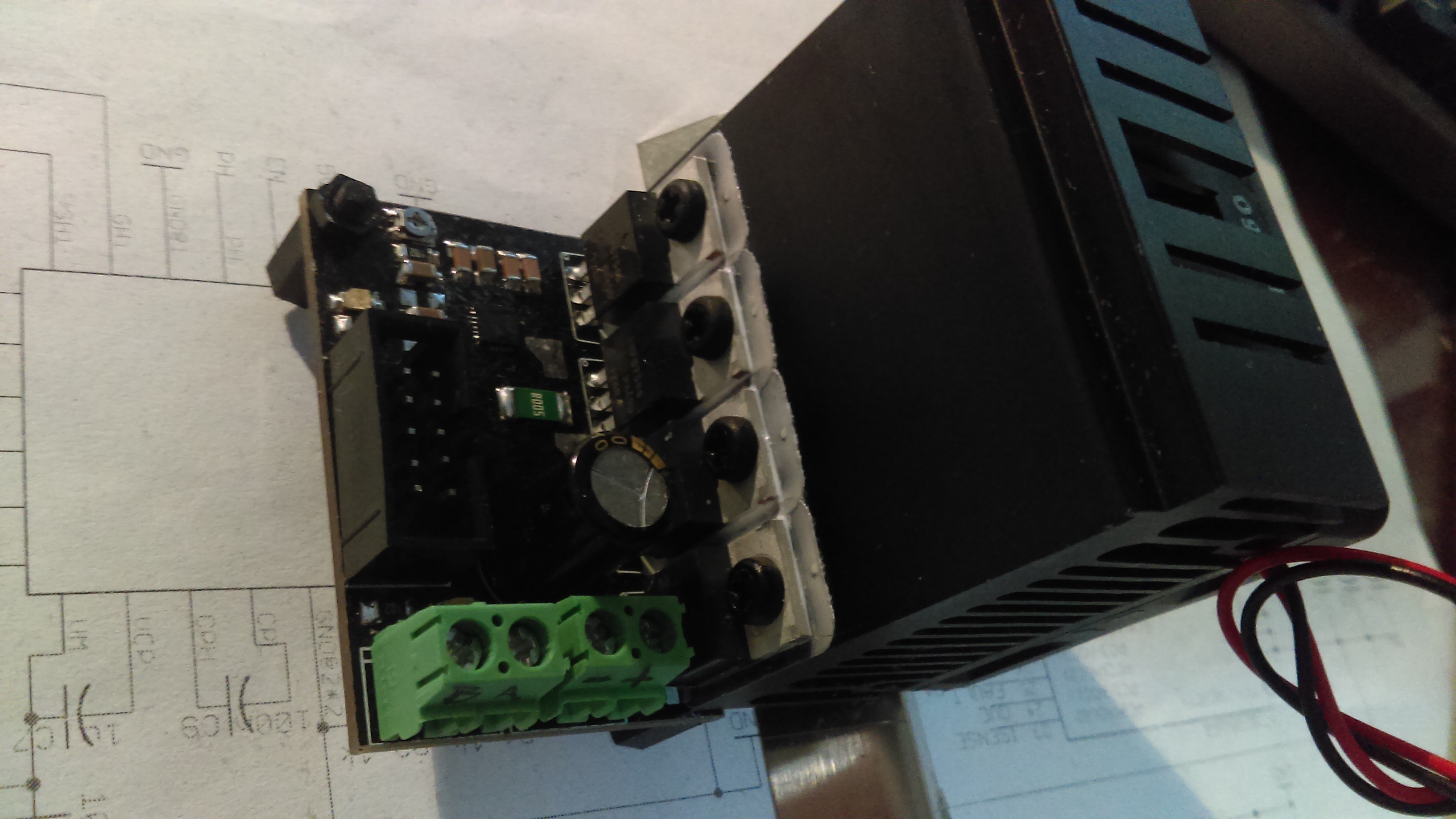
MOSFET driver
A DRV8701 full bridge mosfet driver provides the capabilities to drive the MOSFET gates at an appropriate voltage with acceptable switching speed, while also protecting them from being damaged from heating due to insufficient gate voltage, shoot-through, etc.
The IC also provides a low side current sense amplifier that uses an external 10 mOhm power resistor to produce a voltage drop across it for the amplifier. The MCU reads the amplified voltage signal (gain is 20) easily with an 8-bit ADC.
Finally, the driver also performs a current limiting function to avoid damaging the transistors. The current level is set via two resistors in a voltage divider configuration.
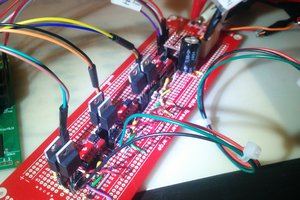
MOSFETs in H bridge configuration
The device utilizes four IRFH7545 MOSFETs. This transistors have a breakdown voltage of 60 V and a RDSon of 4.3 mOhm typically (or up to about 9.5 mOhm at 150 °C Tj) with a Vgs of 10 V.
Device Characteristics
|
Parameter |
Min |
Typ |
Max |
Unit |
|
Motor side voltage |
6 |
36 |
V |
|
|
Motor side current |
0 |
7 |
A |
|
|
Logic side Voltage |
4.5 |
5.5 |
V |
|
|
Logic side current consumption |
20 |
50 |
100 |
mA |
|
Step signal frequency |
0 |
50 |
kHz |
|
|
Encoder frequency (4x) |
0 |
50 |
kHz |
|
|
Error signal output current |
0 |
50 |
100 |
mA |
|
Ambient temperature for operation |
0 |
50 |
°C |
 ottoragam













 JP Gleyzes
 ridonkulus
 John Taylor
I developed a dc servo drive based on the DSPic 4012 and OPA549 amp. I would like to know the status of this DC servo drive.
Thanks