ottoragam
-
Crowdfunding campaing status update
01/18/2017 at 21:23 • 0 commentsAt just 3 days from the end of the campaign, the project is just 800 dolllars away from the goal.
Now is the time to get your own board at https://www.crowdsupply.com/citrus-cnc/tarocco
![]()
-
Funding Campaign Started!
12/09/2016 at 02:25 • 0 comments![]()
The Crowdsupply funding campaign is now live! If you find the project useful please consider backing it.
https://www.crowdsupply.com/citrus-cnc/tarocco -
Take a look at the new servo drive
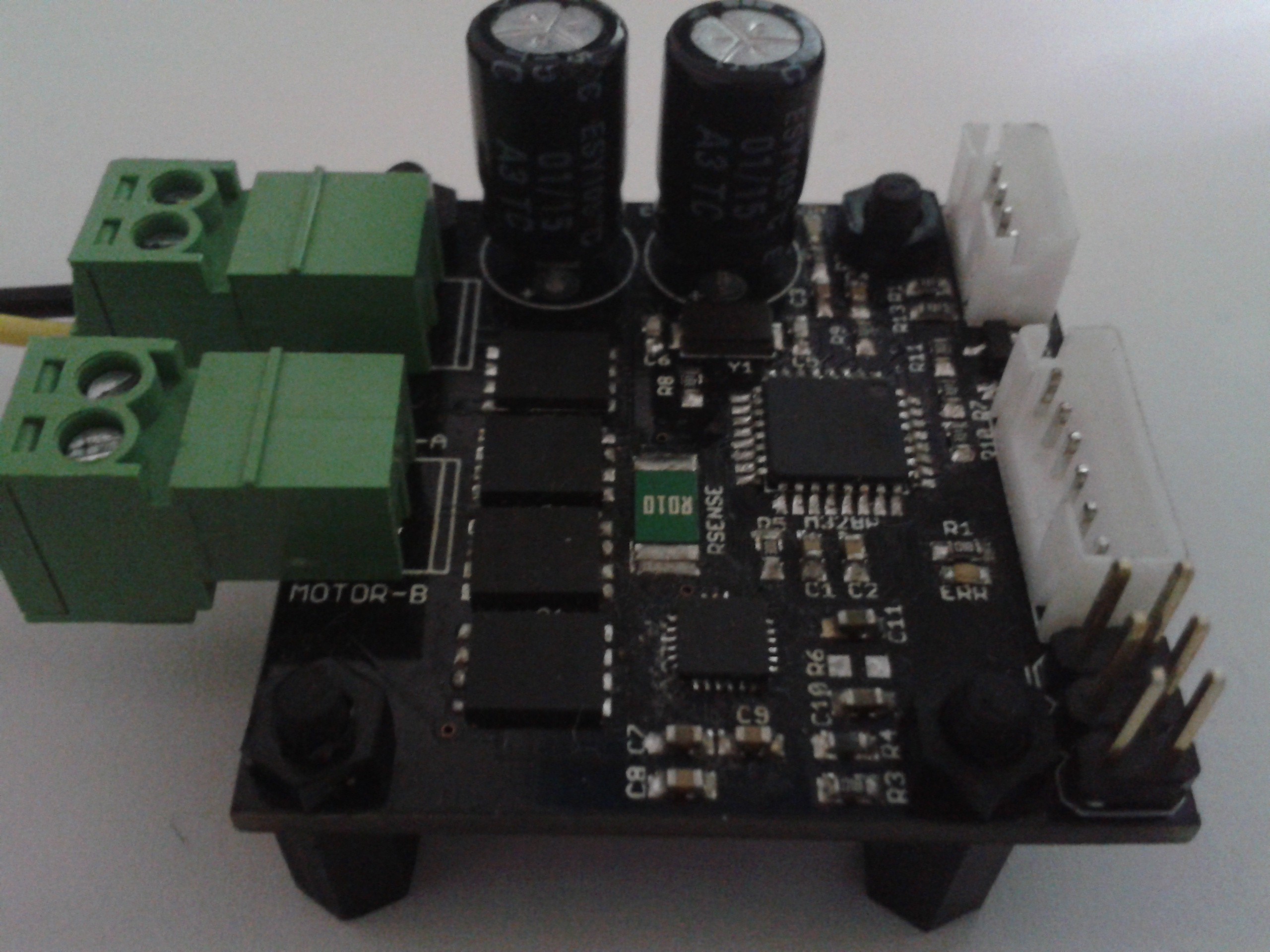
09/26/2016 at 19:05 • 0 comments![]() Just wanted to keep every follower updated on the status of this project. I made a new controller design, for improving mainly the microcontroller and current handling capability. You can check the new project here: https://hackaday.io/project/15025-tarocco
Just wanted to keep every follower updated on the status of this project. I made a new controller design, for improving mainly the microcontroller and current handling capability. You can check the new project here: https://hackaday.io/project/15025-taroccoI'm launching a crowd funding campaing for it too, here: https://www.crowdsupply.com/citrus-cnc/tarocco
-
Circular form factor by Bogdan Fargas
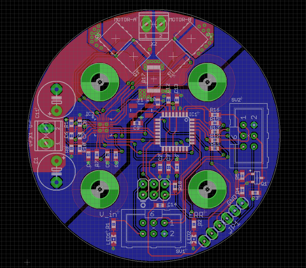
08/23/2016 at 22:50 • 0 commentsUpdate: taking down the design files for this version due to an error. The fix is in the works!
I got an email from Mr. Bogdan Fargas informing me of his modified PCB for servo drive. He needs to control a GR63x25 DC motor from Dunkermotoren for a coil winding machine. He wanted to stack the motor, the encoder board and servo drive board, so he created a circular PCB version of said boards.
I've been given permission to post his files here. Hopefully they'll be of use to some of you!
![]()
-
CNC mill working! (pic heavy)
07/01/2016 at 01:31 • 0 comments![]()
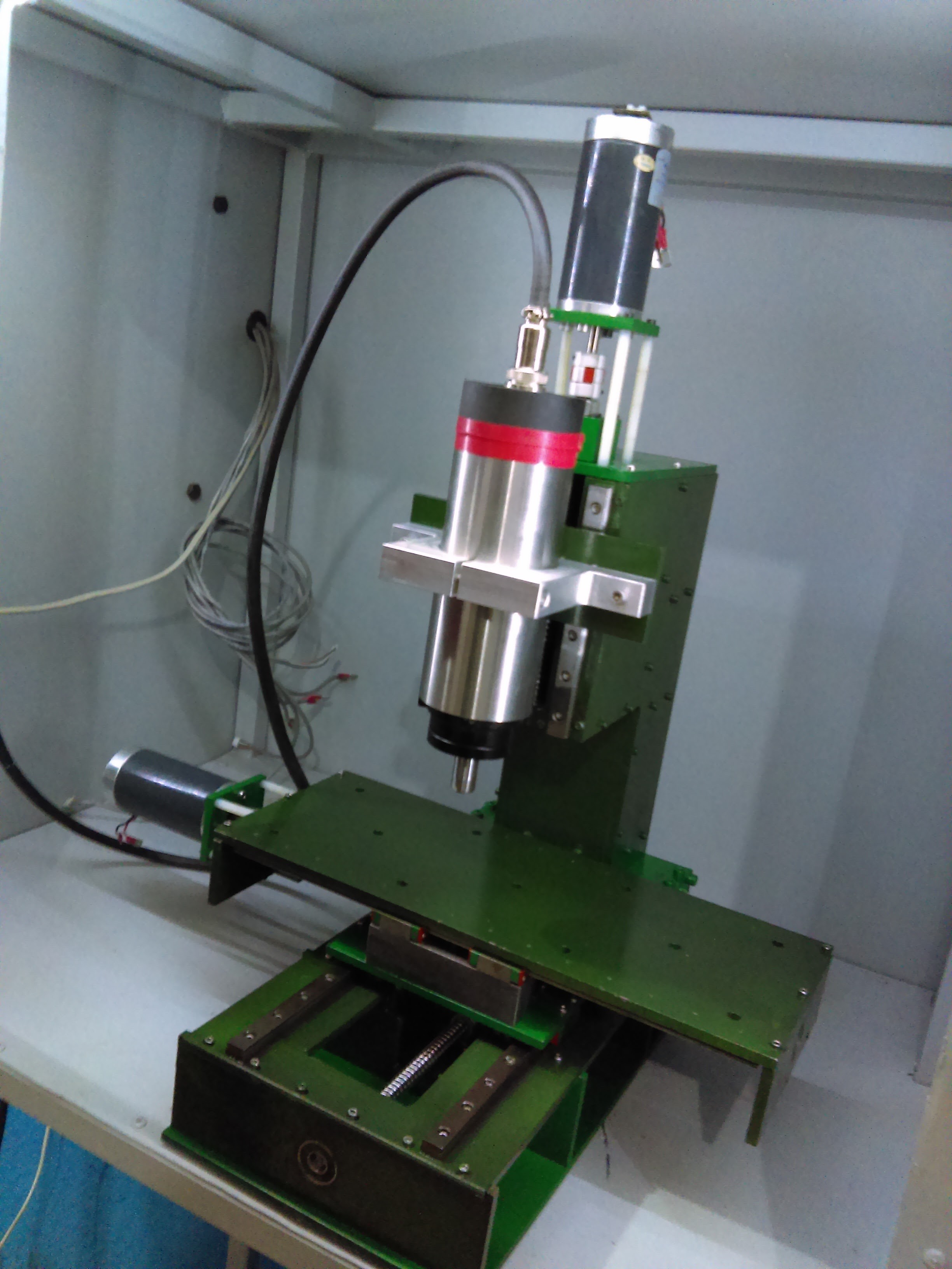
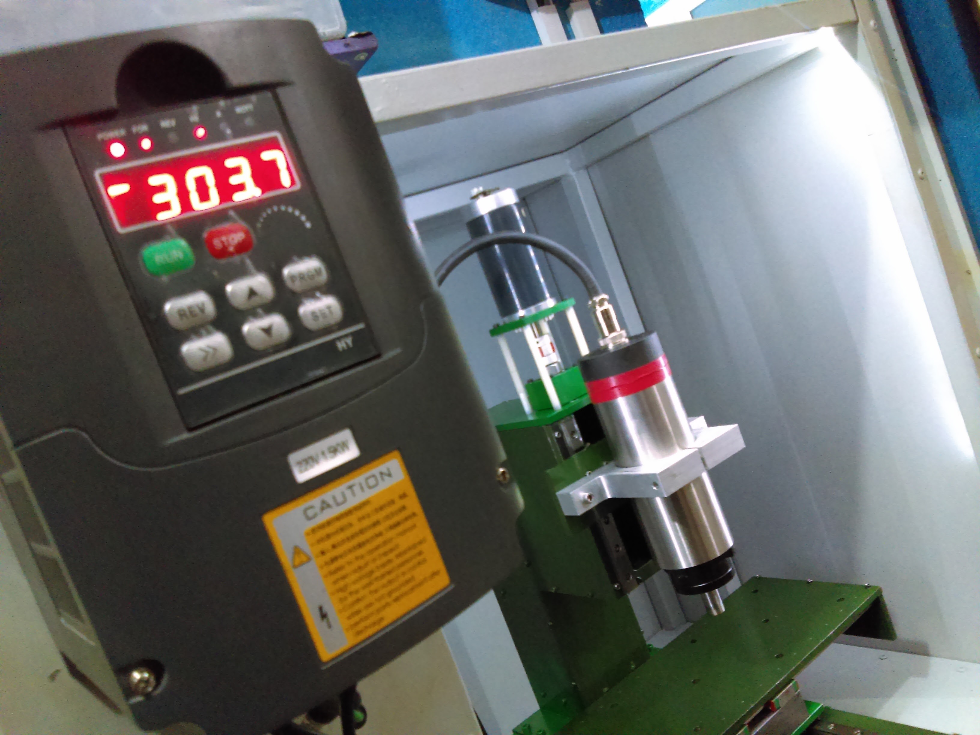
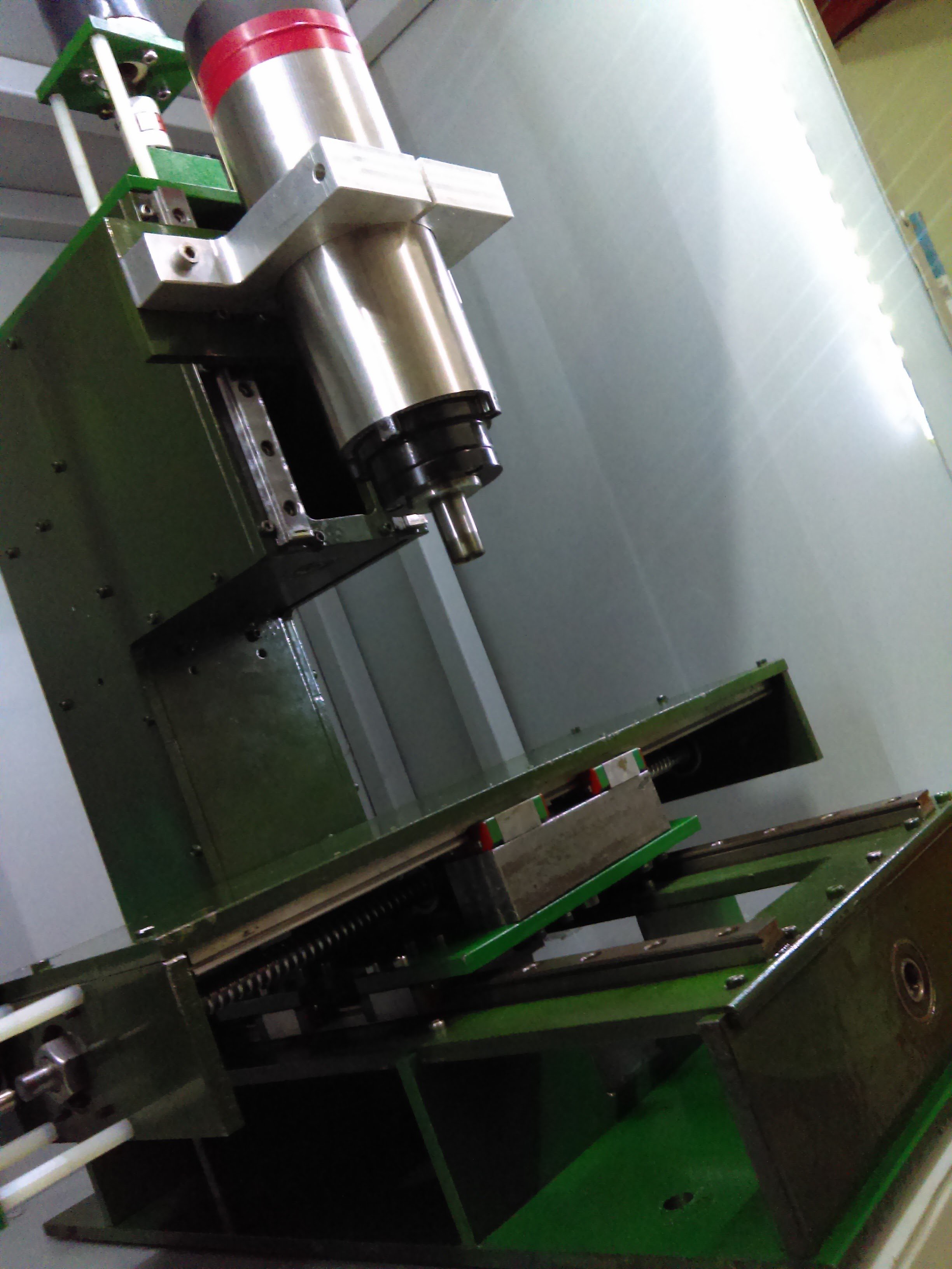
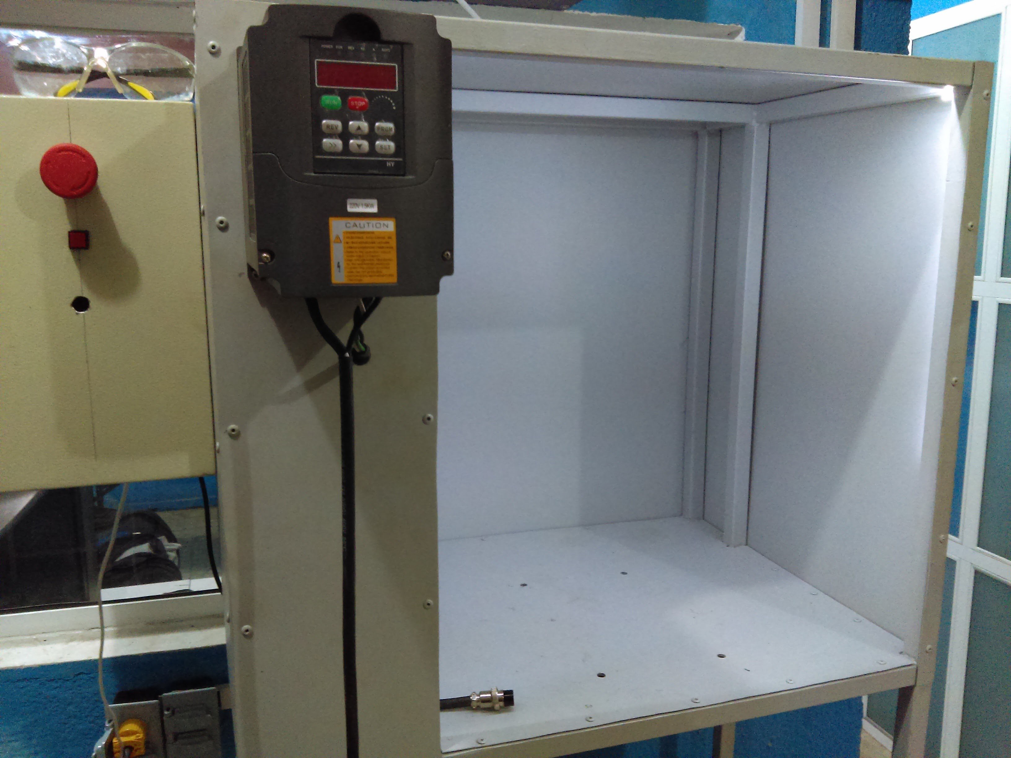
I'm finally done building my CNC mill. For the past half year I've been buying the parts and machining the structure out of 1/4 in thick steel plate on my "bigger" manual mill, a ZAY7040.
The machine characteristics are:
- Weight: 55 kg/ 120 lb (99% steel)
- Rapids: up to 400 ipm/10 000 mm/min
- Motors: 24 V 20 W output power at maximum efficiency brushed motors (60 W maximum output power)
- Linear motion: 12 mm diameter 4 mm lead ballscrews, 12 mm linear rails, back to back angular contact bearings on the fixed side, deep groove bearing on the floating side, spider couplings for the motors
- Travel: 160 x 120 x 80 mm (X,Y,Z)
- Spindle: 800 W 220 VAC three phase synchronous motor
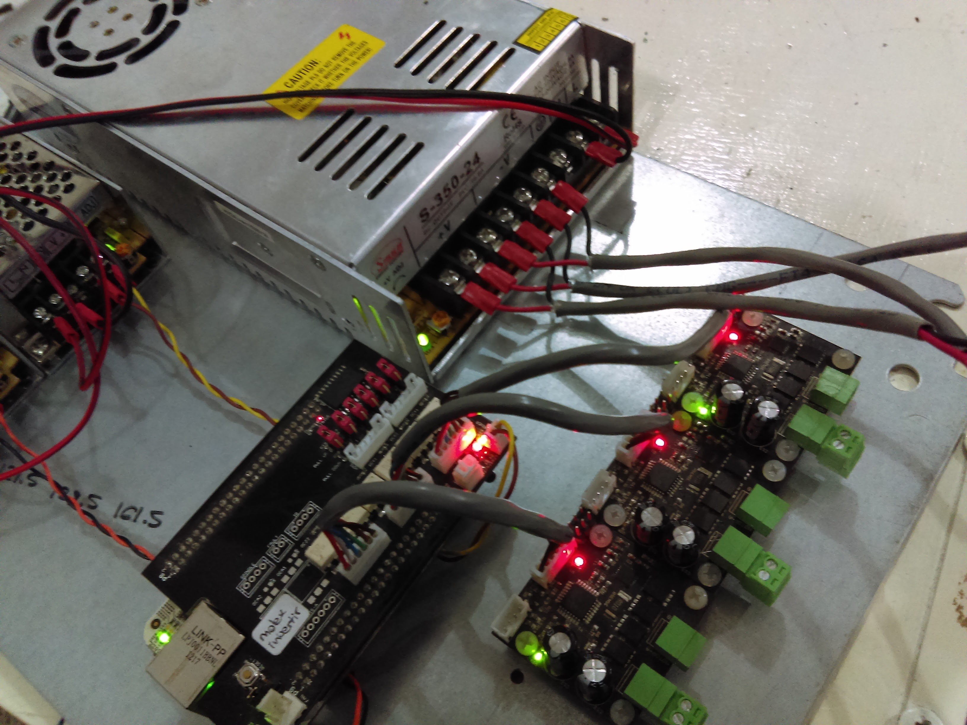
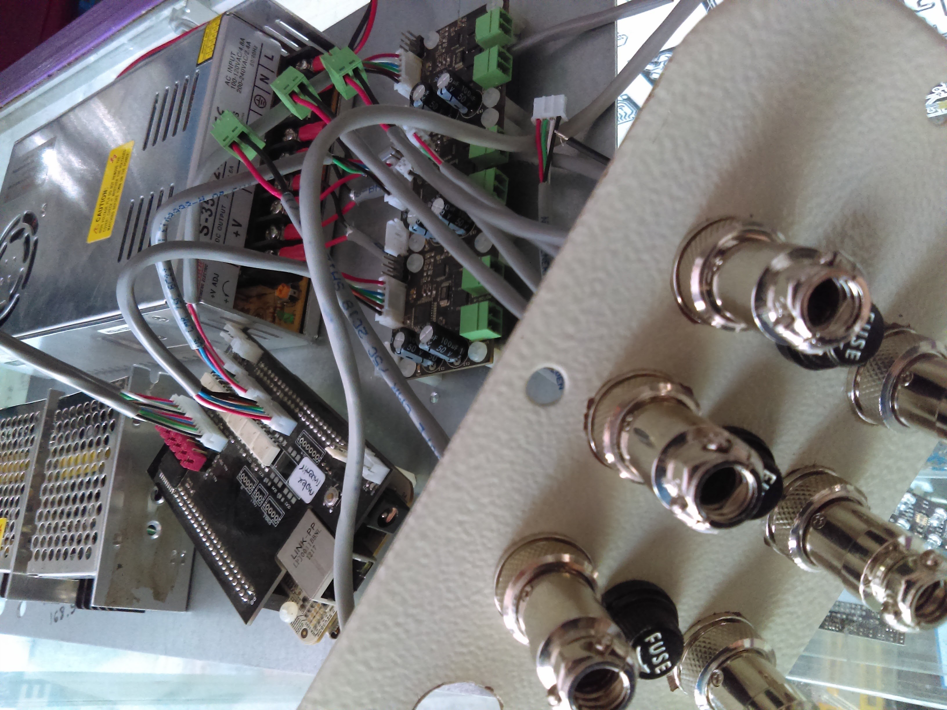
- Motor driver: pretty obvious :)
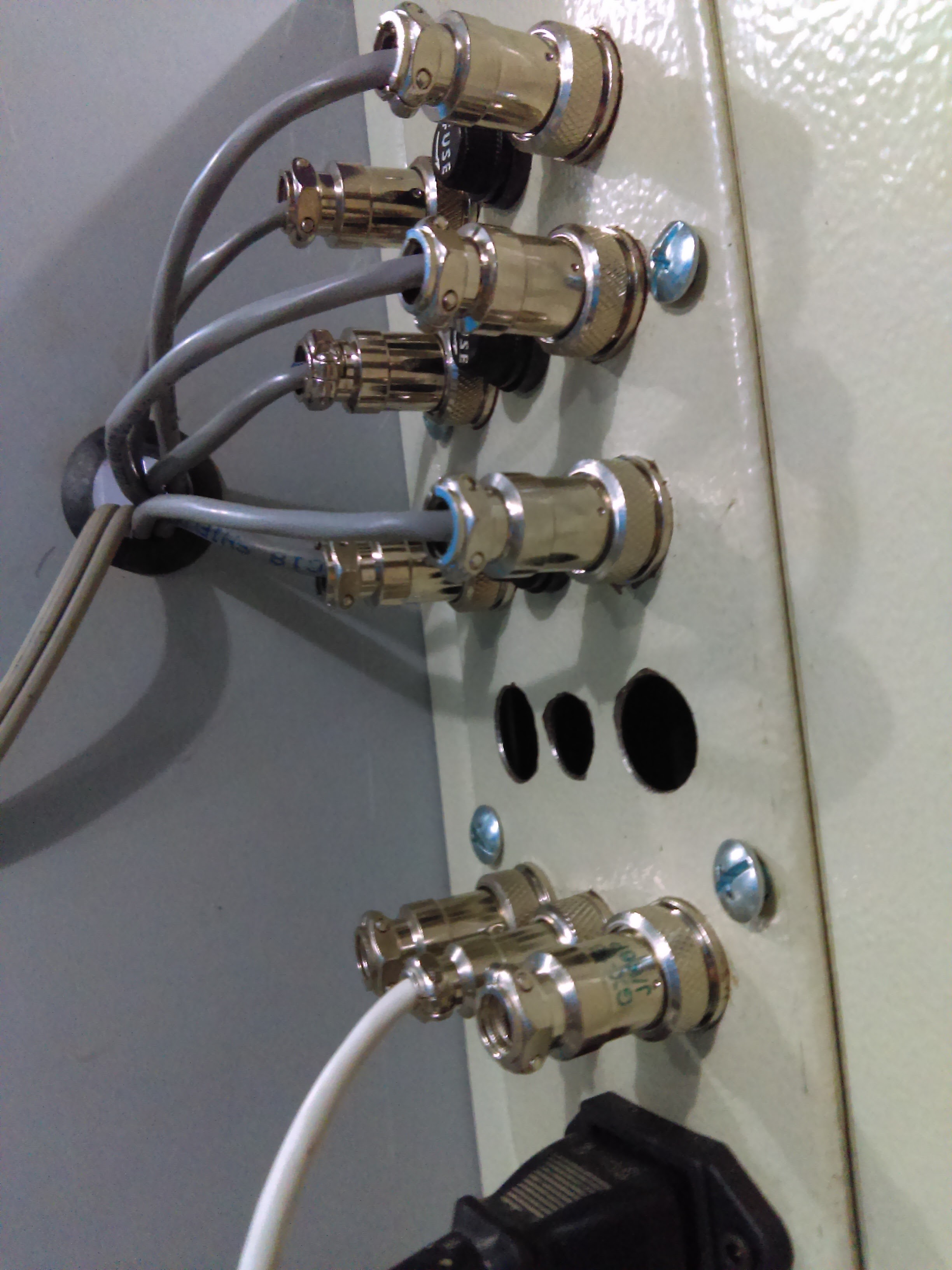
- Machine controller: Beaglebone running machinekit with a custom cape for the signal connectors, e-stop, limit switches...
![]()
![]()
![]()
![]()
![]()
![]()
![]()
![]()
![]()
-
The commercial side of this thing
06/03/2016 at 23:52 • 0 commentsI've been working with James Newton, of Linnistepper fame, on an open source commercial low cost closed loop motor conversion system. An encoder board is available for sale, along with a PIC based PID controller.
![https://cdn.hackaday.io/images/5569361461622297516.jpg]()
The relevant links are here:
Hakcaday.io project
https://hackaday.io/project/11418-massmindorg-abosoluteincremental-rotary-encoder
Purchase here!
http://techref.massmind.org/techref/io/sensor/pos/enc/ENC1.htm
http://techref.massmind.org/techref/io/servo/BOBPID.htm
This project may also be of interest to some of you. It is a low cost 40V 18A H bridge based on the same FET driver as my smaller servo drive project, with some easier to cool transistors.
![https://cdn.hackaday.io/images/5344591461622861291.jpg]()
https://hackaday.io/project/11419-massmindorg-40-v-15-a-output-dc-motor-drive
-
Avoiding motor runaway
02/26/2016 at 08:23 • 0 commentsThe other thing I wanted to address is the detection of a faulty encoder, in particular, I want to be able to handle the loss of the quadrature signal and an incorrect A/B channel wiring.
First, motor runaway caused by an inverted encoder channel signal is controlled via programming a following error check. When the driver tries to rotate the motor in one direction, the encoder will output a poulse train that corresponds to rotation in the othe direction, thus incrementing the error magnitude until it surpasses the following error value, and when this happens the driver stops the motor.
This test also gives the driver the ability to signal when the motor is lagging too much and avoid ruining a CNC job.A encoder signal loss also causes motor runaway. We could analyze the following cases:
- Lost encoder signal and STEP input present. In this case, the error will grow each time a STEP pulse is present, until the following error value is reached, and an alarm is raised/motor is stopped.
- Lost encoder signal and no STEP input present. This case happens when the motor still needs to move an amount of "steps" that is below the following error value. The two conditions I'm using to determine if this case occurs are: comparing the current encoder state to an inmediate previous one to see if the signal changed, and checking if the STEP input is firing. The tricky thing with this heuristic is that not changing encoder signal + no STEP input conditions happen also in normal operation, when the motor has reached the desired position and is waiting for the next move.
Becasuse of that, I can't just make the driver signal a fault when those conditions are met. One could think on cheking the PID output value too, to see if the motor is commanded to be moved when the encoder state is not changing, by looking at the duty cycle value, but that's not really a reliable option because of the value that we compare the duty cycle against may not be easy to determine, as it varies with the PID calibration, motor cogging, etc.
I decided to just zero the duty cycle if the two conditions I mentioned are met for a certain number of times (to filter false positives). This way, I avoid motor runaway, but I also allow the servo drive to further receive STEP signals in case everything was functioning correctly.
The driver must perform the aforementioned tests continuously to be able to stop the motor at any time if something occurs to the encoder.In the following video I start the motor and apply pulses to the STEP and DIR inputs. The algorithm discerns between a finished move status and a disconnected encoder status, and stops the motor when the encoder gets disconnected (and lights the LED).
I'll upload the updated code to the project's repo. I also need to program something to detect when only one of the encoder channels is lost. -
Servo drive speed test
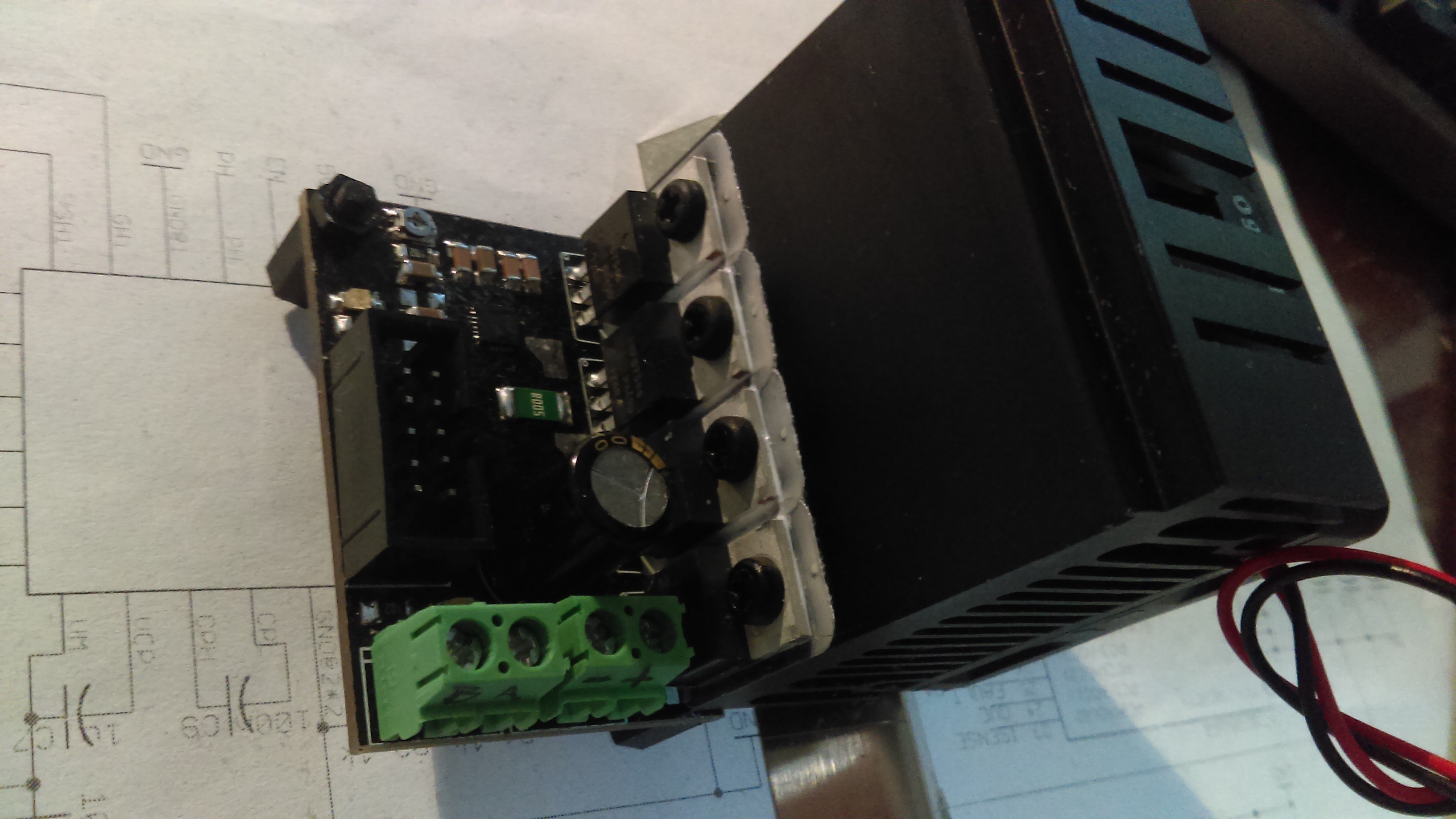
02/26/2016 at 07:35 • 0 commentsI wanted to find if the controller could accept a higher STEP pulse frequency, so I took out a Mitsumi printer motor with an integrated encoder (334 divisions, 1336 cpr with 4x decoding) from my parts bin.
I programmed another MCU to generate a 83 kHz square signal, and fed that signal to the servo drive. I also updated the quadrature decoding routines to light the error LED when the encoder state changes to a value that doesn't correspond to the previous or next step with respect to the current step in the sequence. I couldn't make the LED to light, so I'm assuming that the AVR is not missing any pulses.![]()
One could argue that the MCU may be missing more than one step pulse, thus not meeting the error condition, but I find very unlikely that the microcontroller misses the "correct" amount of puses tens of thousandths of times during the short test.
The video shows me measuring the signal frequency on one of the encoder channels, and then measuring the STEP input frequency, wich is nearly 4 times higher as is supposed to be.
You can see the error LED turning on at the end of the video when I disconnect the encoder, causing the drive to detect an erroneous quadrature sequence.
-
A few more details...
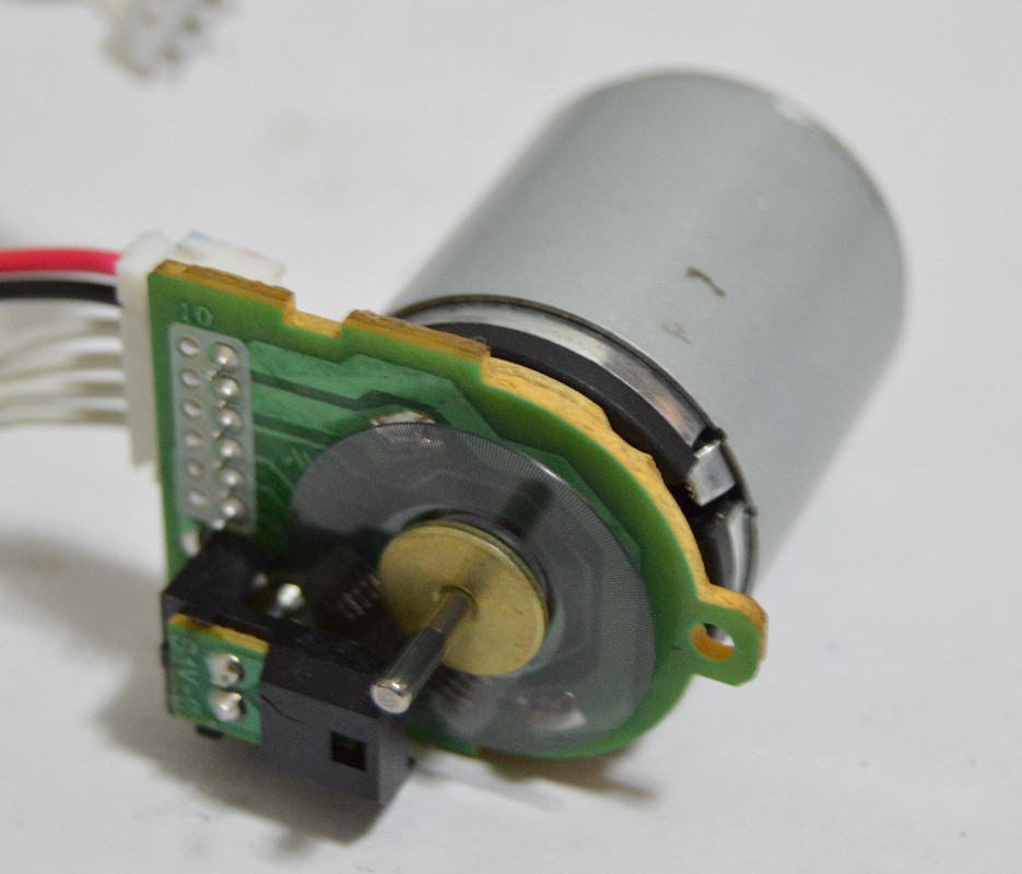
02/08/2016 at 01:53 • 0 commentsI present you with the motors I'm using for my milling machine, and a video I took for my quadrature encoder project of the servo drive controlling the "steps" of one of those motors, and the accelerating and decelerating it.
![]()
![]()
I'd also like to add a to do list:
- Add serial interface for configuring PID parameters without recompiling and uploading the firmware.
- Create a GUI for adjusting said parameters
- Change 100 uF capacitor footprint
- Change current limiting approach (I think it would be better to utilize the MOSFET driver's current limiting function instead of the uC for this task).
- Add more indicator LEDs
- Desgin a case
-
A little background
02/06/2016 at 03:33 • 0 commentsThis project came to be when I became tired of searching for a commercial option for closed loop position control for a CNC machine I'm developing.
The majority of the retrofit CNC drives I found were stepper motor drives, and altough many brushed or brushless drives exist, they're more expensive than the stepper drives ($100 USD and upwards).
Going into hobbyist controller territory, another issue arises: a lot of the commercially available designs are IC based, and frankly, motor driver ICs are shit. They have too much internal resistance, and they're more expensive than a MOSFET/gate driver combo for switching the same load.
I did manage to find some discrete transistor designs that were the right price, but some of them weren't usable at the current or voltage I require for my motors, or were not designed to receive feedback from a quadrature encoder.
I decided then to develop my own brushed motor servo drive. Why brushed and not brushless? Well, because brushed motors for this kind of application are easier and cheaper to find. You can buy some very very good surplus motors, take them out of machines or buy some cheap gearmotors and use them with or without the garbox, in contrast with the BLDC motors, RC ones are the only cheap option, and those spin too fast and may need cooling when used in a non moving machine (as in not an airplane).
Then, I decided that 250 W of output power (per controller) was more than enough for a desktop CNC machine. Lets take a look at an example case:
I got some 24 V 20 W rated (output) motors. They develop 700 gcm of torque at 3000 rpm. For this, they consume 1 amp, so the input power is:
where P is power, I is current and V is voltage. The output power and efficiency are
where E is efficiency, Tau is torque and Omega is angular speed. The efficiency is really nice (it may be the manufacturer inflating numbers a little). I chose to use 5 mm lead ballscrews in my machine. So the thrust my motor is going to generate is:
where F is force, Tau is torque and L is screw lead (assuming 100% efficiency of the system). And the axis could theoretically move at 15,000 mm/min.
So if with 20 W of motor powerwe can achieve that, why are 250 W needed (in this case 168 W, I'm powering the motors with 24 V, remember). Well, the axis may need more torque when pushing the material against the tool, and when the motor develops more torque, it slows down, and uses more current, until it stops spinning completely, and when this happens, its output power becomes zero but its output torque (along with the input current and thrust) reaches its maximum. In my motor's case I have 6,000 gcm of torque at 7.5 A. So the power being used by the motors is 180 W, a bit higher than 168W, but the thing should be able to handle it. In fact, the screw terminals are the thing that limits my current, the ones I'm using are rated for 8A. That's why I need the full power output from my servo drive, to reach maximum thrust (about 740 N).
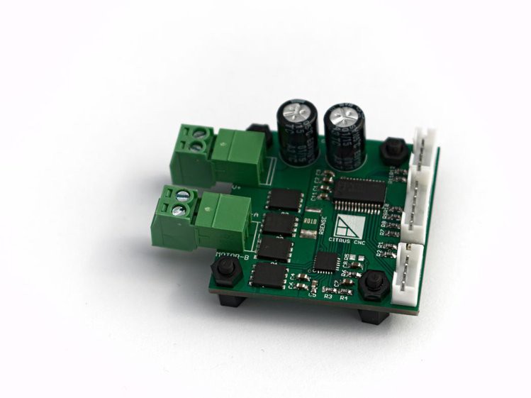
Finally, I decided that a small footprint would be preferable. I was able to lay out my board in a 40x40 mm area, using 2 layers. Perhaps in the future I'll change the design to use 4 layers to improve MOSFET cooling and reduce EM emissions.

 Just wanted to keep every follower updated on the status of this project. I made a new controller design, for improving mainly the microcontroller and current handling capability. You can check the new project here: