Blake W. Ford
-
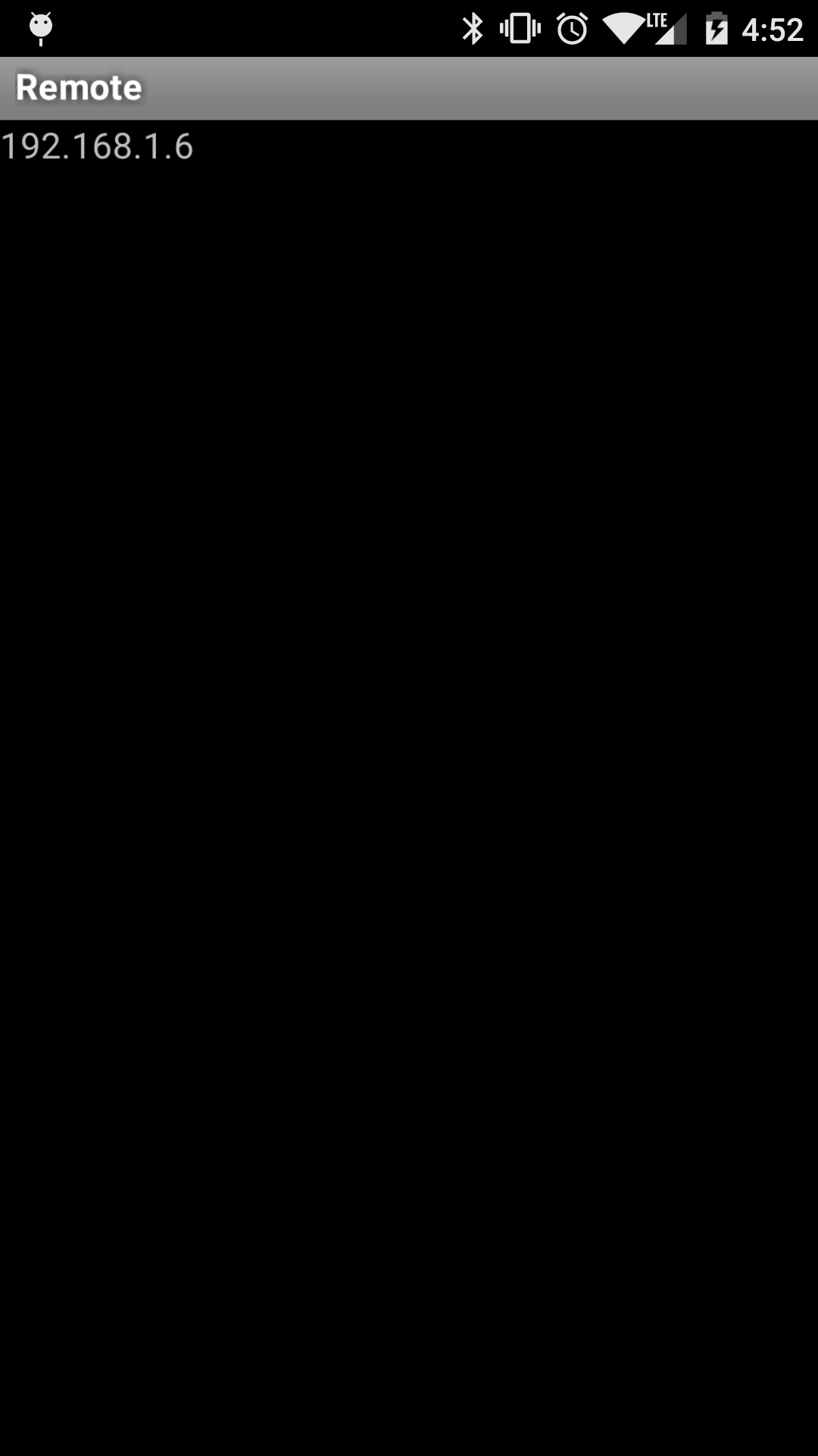
Started Android Based Remote App
03/20/2016 at 21:55 • 0 commentsI have done the most basic levels of work to get an Android based remote up and running. This works as an alternative to the python based server I am using on the desktop. Currently the car will always be in the IDLE state while using the app, as I have not yet added any controllable UI elements. Source is available on the project's GitHub page.
![]()
-
Battery Install
03/20/2016 at 04:27 • 0 commentsI installed the external USB battery and made a minor change to the Arduino code. Now everything is working basically as expected. See the test video in the link below. It is becoming increasingly clear that the test car is out living its usefulness. Once I add steering and the head/tail lights I will likely ditch it for a more capable model.
![]()
![]()
-
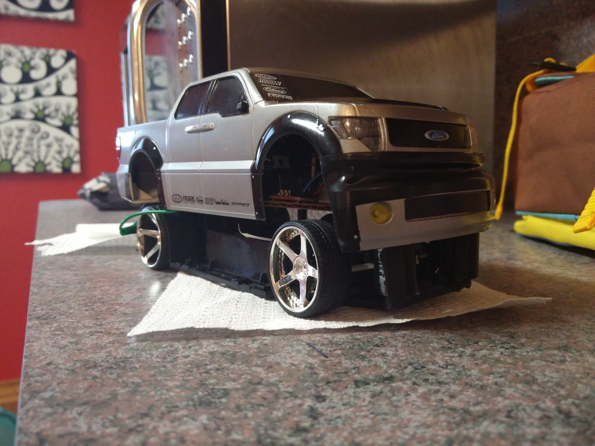
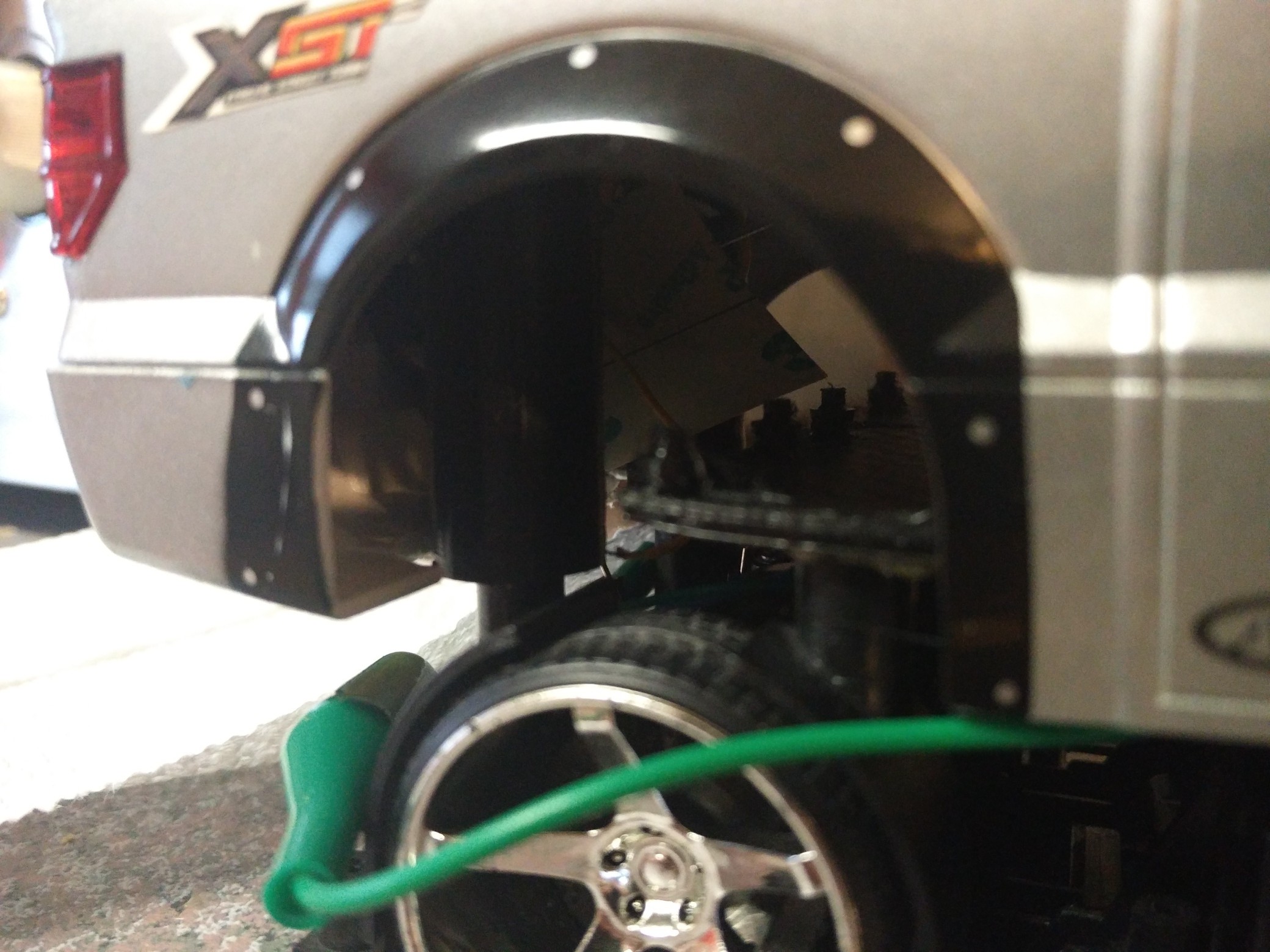
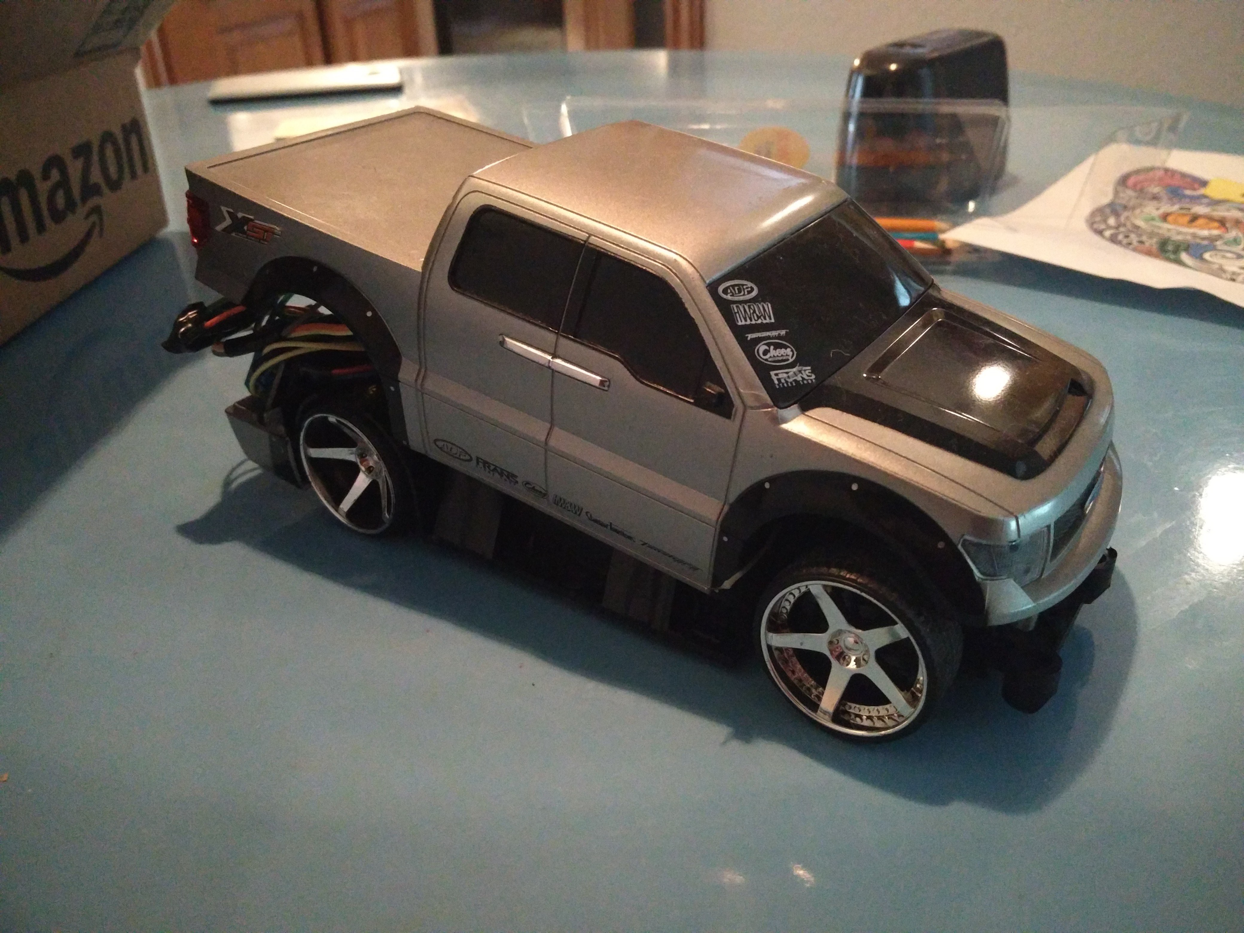
Truck Lifted
03/16/2016 at 23:43 • 0 commentsI designed and printed a simple lift kit for the truck. The overall lift is about 30mm
and the supports themselves are 16mm in diameter. I put in an order for the battery and USB hub. With the latest round of modifications the truck should be mobile, minus steering, next week.
![]()
![]()
![]()
-
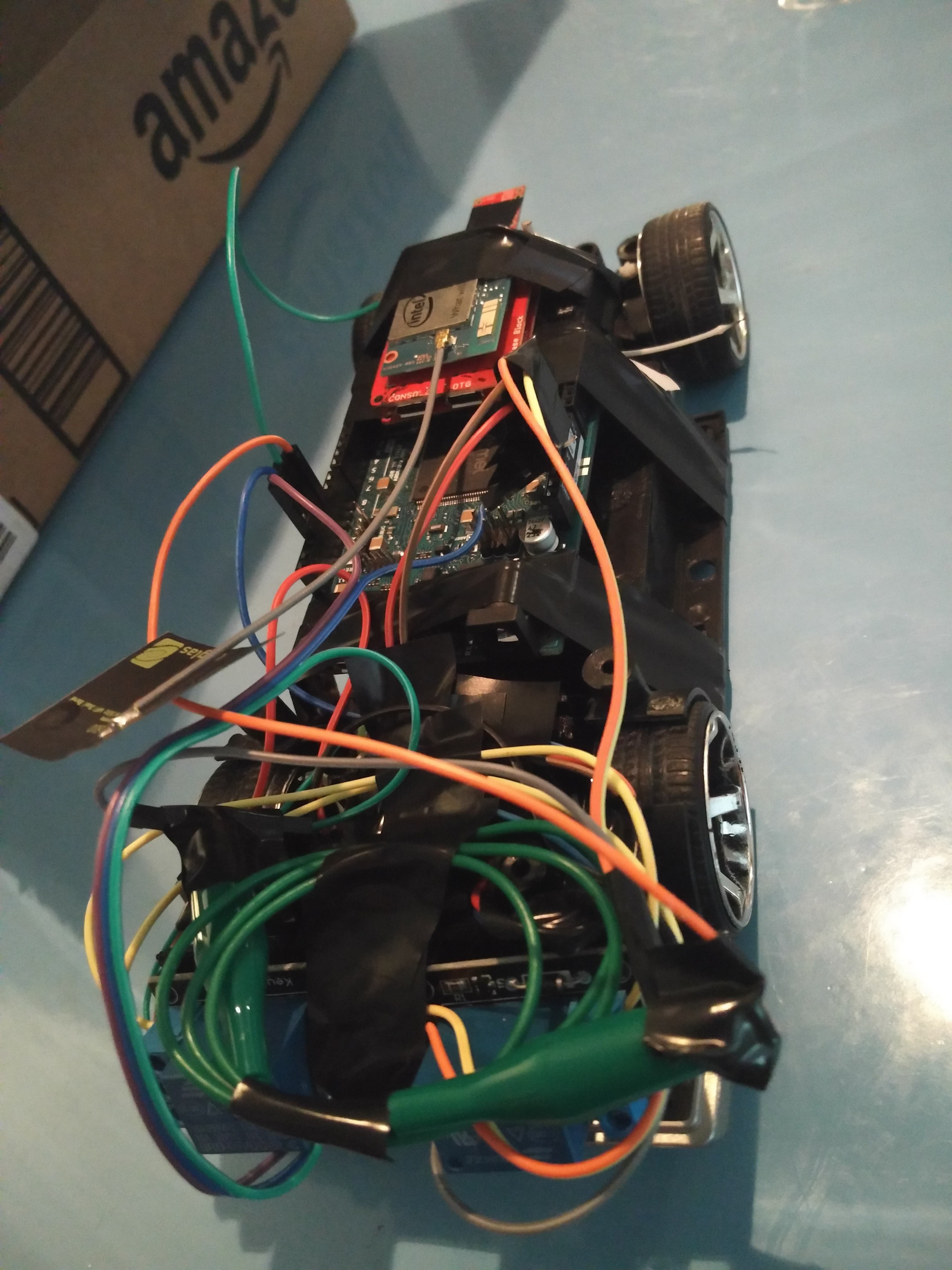
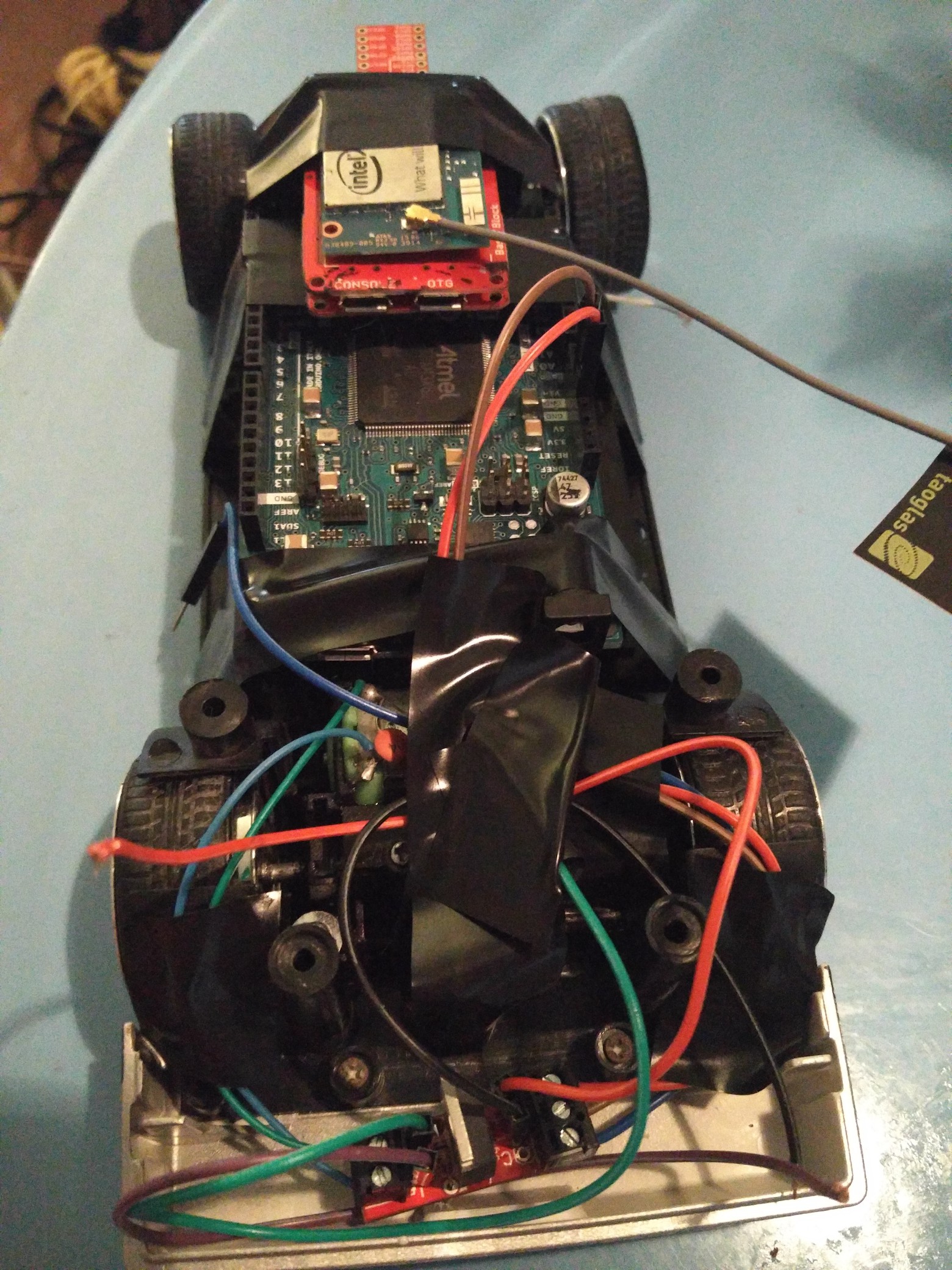
Repo updated, miniaturization process completed
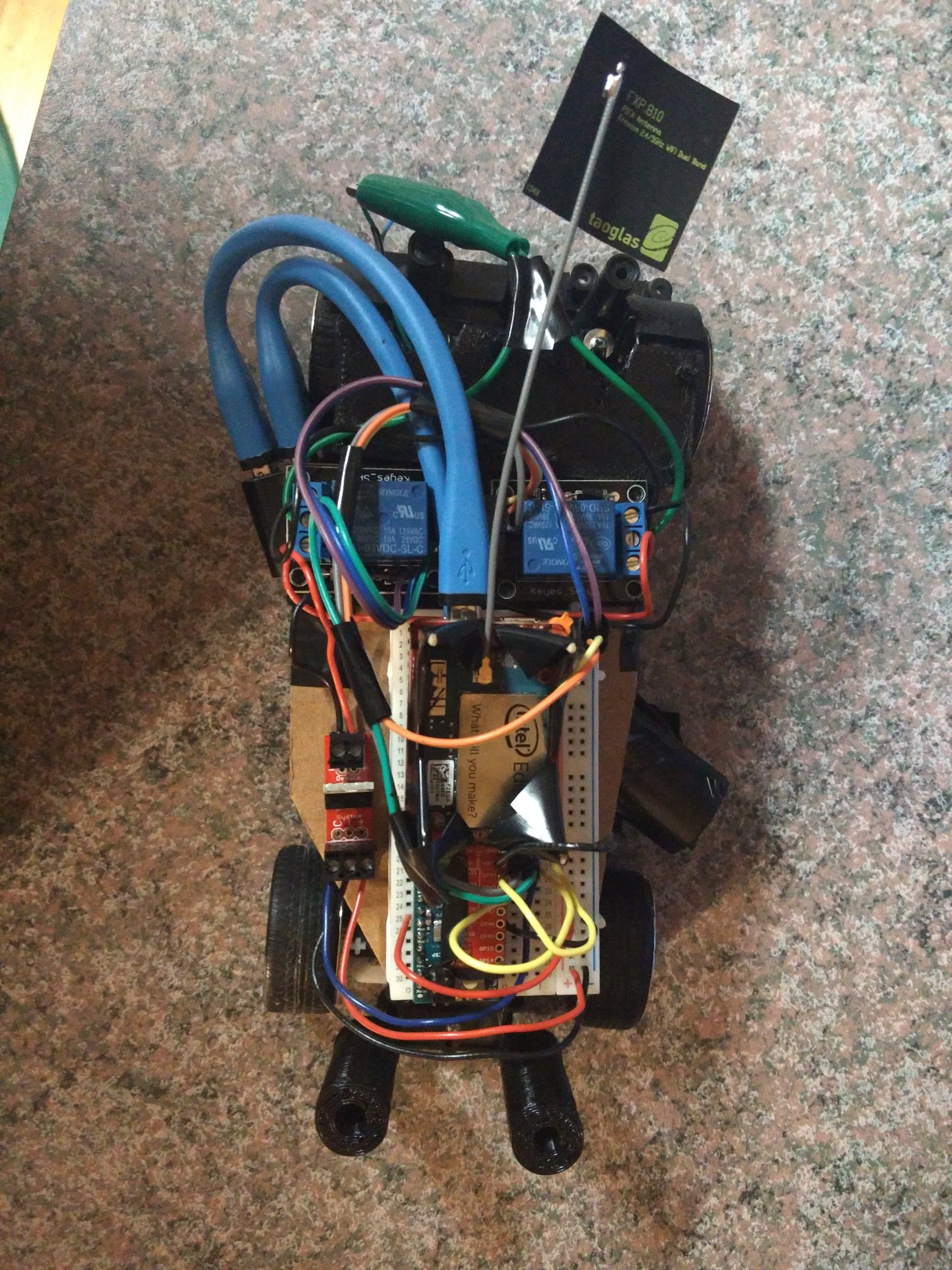
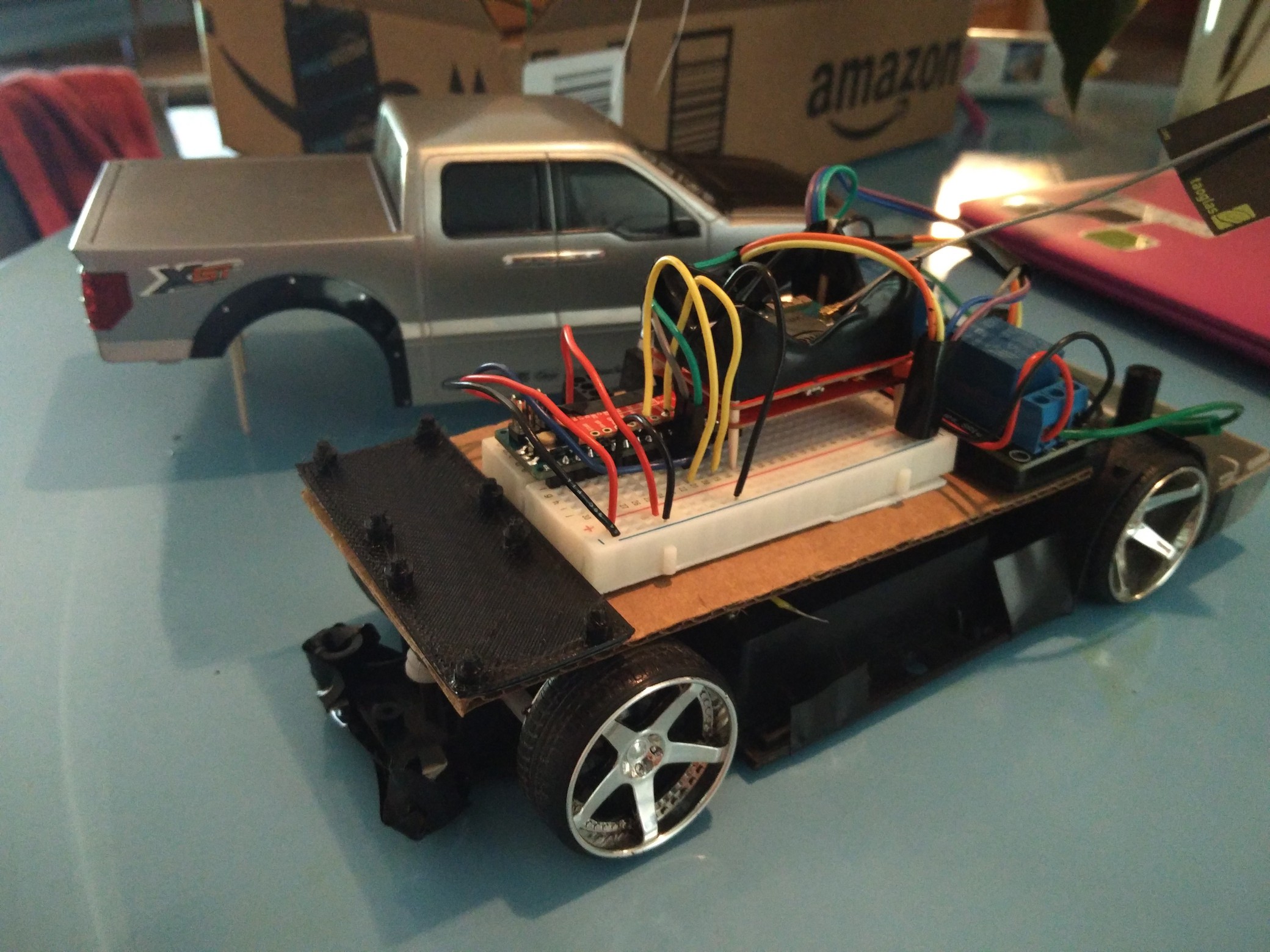
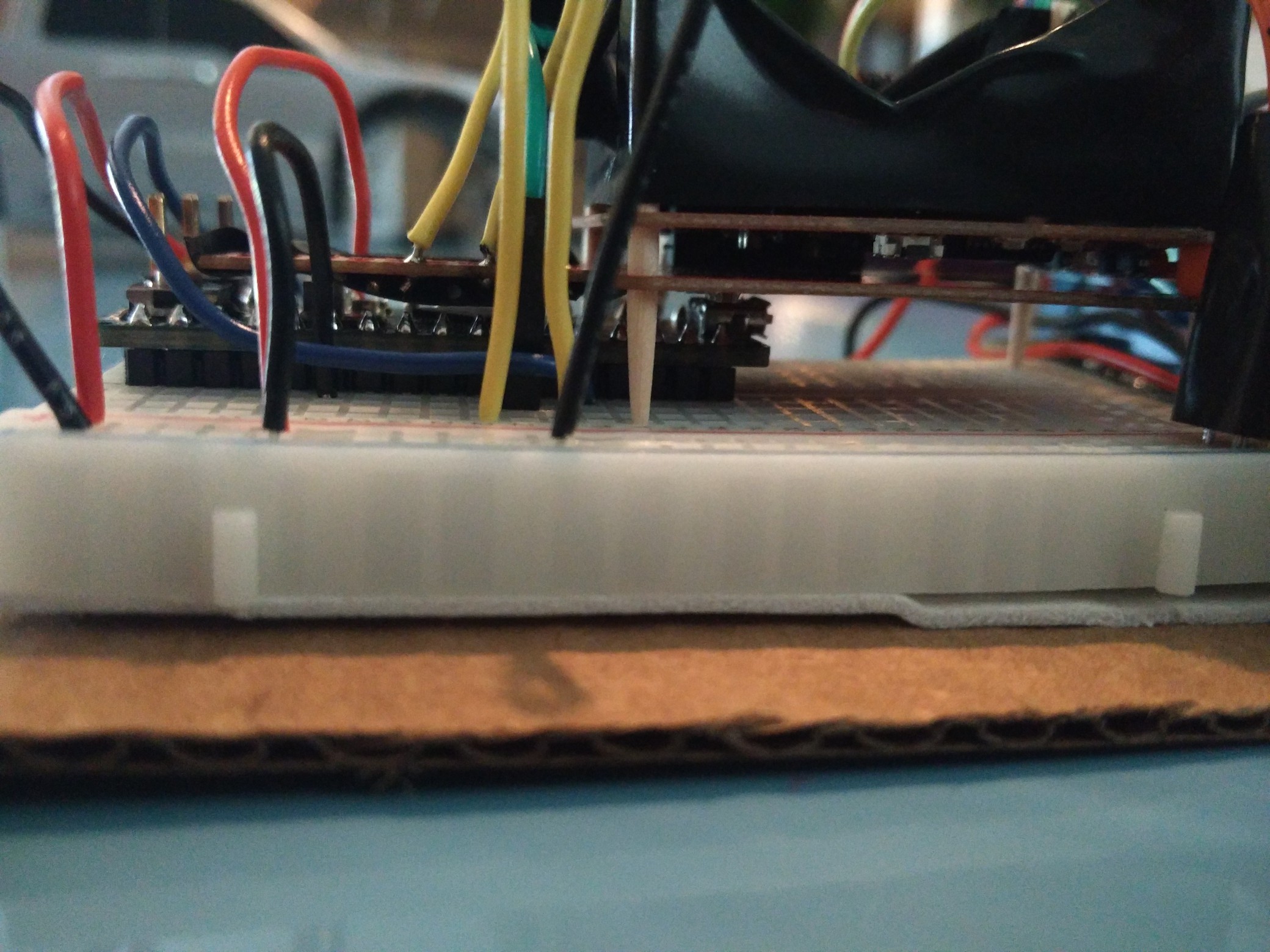
03/15/2016 at 01:56 • 0 commentsI finally have a product which is a bit more manageable. The first pass of working drive train code is in the repo. You can see the rolling chassis as well as the top and side view below. Now the board is powered by an Arduino Micro. The whole setup makes the car about 25% heavier and is much larger than the board it replaced. The original was approximately 2.5"x1.25" in. Hopefully I can put enough smarts into the code base to make the switch worthwhile. When shopping for my next vehicle I plan to get a much higher quality truck capable of easily displacing the weight. I've reasoned about how far I have to jack up the body to fit everything, so I will likely create some custom support pillars next.
Once I am satisfied with the back end, I am planning to install an external smart phone battery and a two port USB hub(one to the Edison, one to the Micro) to power the car remotely. I also want to make a dead man switch in case the two microcontrollers become disconnected from one another. I plan to add steering last as that should be a redundant operation.
![]()
![]()
![]()
![]()
-
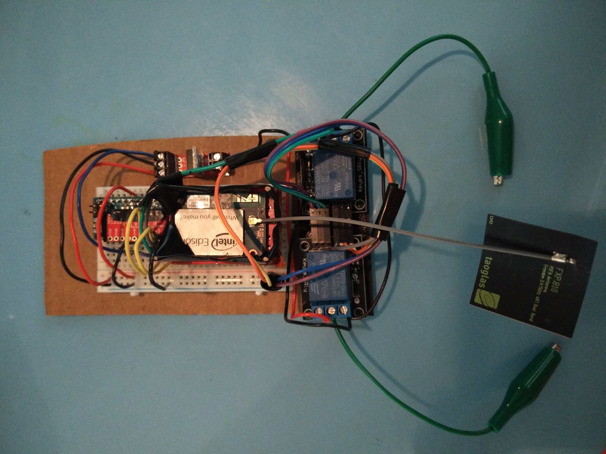
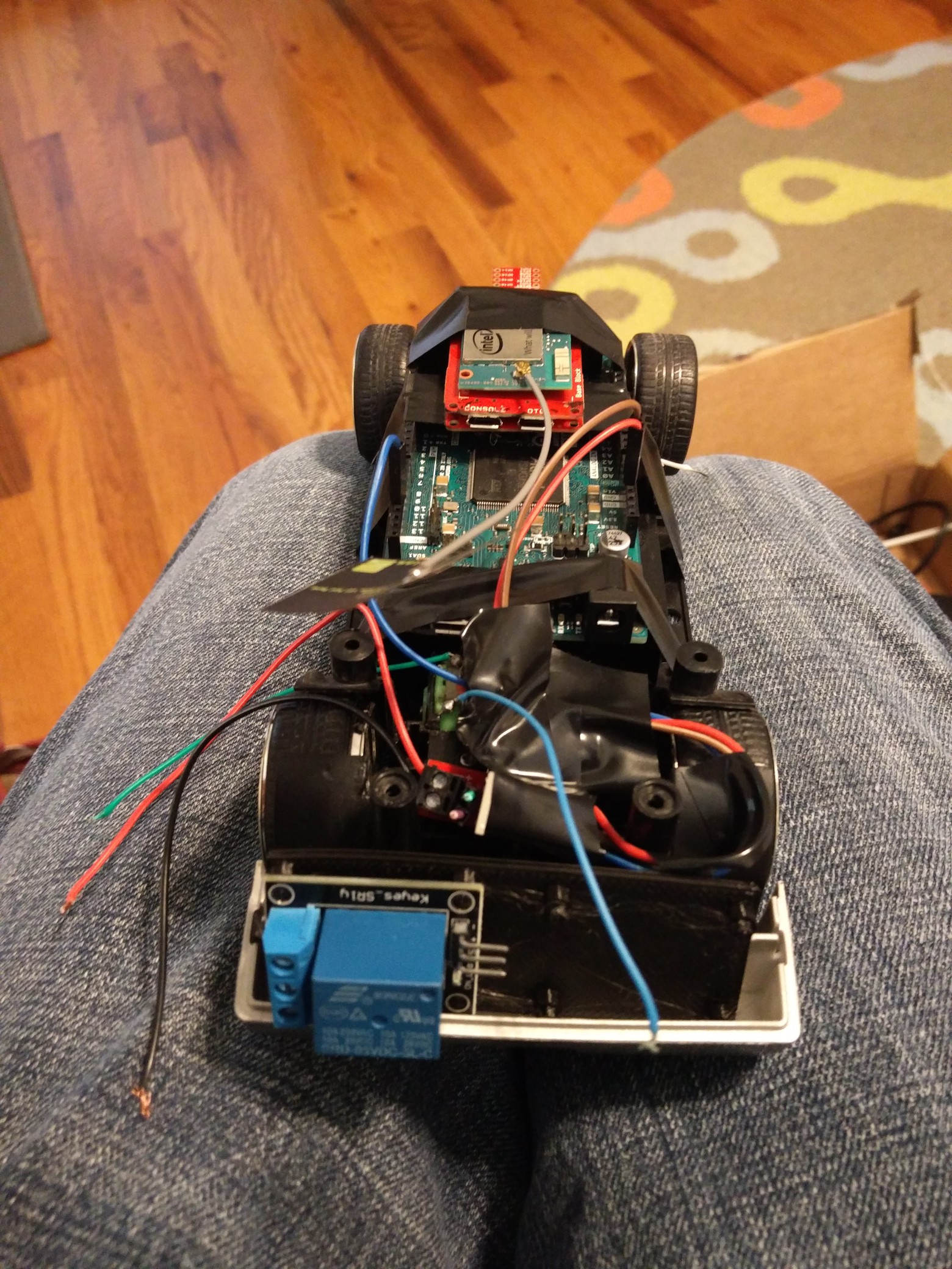
Backend wiring complete
03/11/2016 at 23:33 • 0 commentsI finally received a second working relay and did the first pass provisional wiring. Everything is working as expected at the physical layer so I am going to put the next round of work into the software. Once that is updated I plan on doing a miniaturization pass before wiring up the front.
I am unsure of how involved or high end the result of the shrinking operation will be. I am definitely keeping open the option of lifting the truck body considerably in order to get the final result to fit.
I do not anticipate actually driving this model. Mostly I want a desktop test bench for software, but as I work towards a fully working version I want to maintain hardware parity. This way I have one failure platform and as little rogue wiring to deal with as possible.
![]()
![]()
-
Finally Reversible
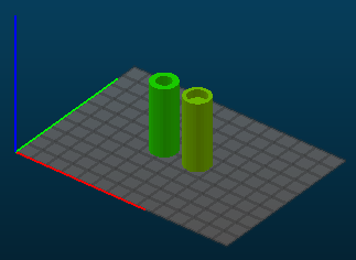
03/08/2016 at 17:50 • 0 commentsSo I have what I anticipate to be my final solution for both the front and back reversible motors. The Arduino trigger pin is used to enable a MOSFET. The output from the MOSFET will be routed through two relays but attached in opposite order on each in terms of NC and NO. I made a small 3D printed part to house the relays. Here is the view of the drive motor.
![]()
Sadly, one of the relays I received was non-functional, so I have to wait a few days to wire the back end up. Once that is working, I will push a software update that includes the Arduino code and start mirroring the setup for the steering. I will update the .STL file for the relay housing soon. My Materia 101 isn't insanely capable, but it gets the job done. I quoted the print through UPS and the going rate is $14.
![]()
![]()
-
New layout
03/04/2016 at 00:52 • 0 commentsI am completely abandoning using the Edison to power the drive components. For now I am using an Arduino Due triggered by the Edison. I could have easily gotten away with a less powerful AVR board, but I had this on hand.
To facilitate reverse I have a relay on order. Forward motion is working as expected and once I get both directions up and running I will duplicate the setup for steering.
![]()
-
Component Swap
02/12/2016 at 04:33 • 0 commentsTo facilitate switching I will attempt to swap out the MOSFET for a Logic Level Converter. I'll update after I trying this which, with shipping, will likely be early next week.
-
MOSFET Failure
02/09/2016 at 03:48 • 0 commentsI received and built several MOSFET control blocks today. Current status is that I can switch properly when directly using the 3.3V rail from the GPIO Block, but not when using a GPIO pin. I have no idea why as of now.
-
Road Block
02/02/2016 at 18:59 • 0 commentsSo I hit my first snag in development, see below. Current status MOSFETs ordered. I had considered re-engineering the original car's board, but I think this will yield a higher quality result. Ugh, I only need 20ma or so to drive the motors and I feel like that is achievable with a Arduino GPIO line. A hidden personal goal for this project however is to dog food many of the products I have worked on over the years, which includes the Tangier chip.
From the SparkFun Edison Hookup Guide...
Using the GPIO Block as an output deviceIf you want to use the GPIO Block to control high power LED’s or Relays, an external transistor or MOSFET will be required. It is possible to illuminate a small LED directly from the level shifter. It may not be as bright since the current output of the TXB0108 level converter is very low (~5ma).
wifiRC
Anything goes digital transition for radio control appliances. Like HDTV, but for RC projects