 JohSchneider
while the front solder pads line up nicely


the through-hole solder-points for the usb connection do not :-(
another problem - which wasn't visible in the pictures of the pi zero - is that the back side is not completely empty and flat
, the hdmi socket has some mounting tabs which protrude a tiny bit
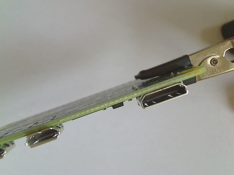
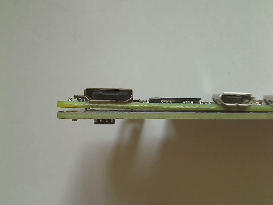
will have to include some sort of cutout to accommodate those :-\
this is what happens if you start designing a PCB without the major components at hand to recheck the dimensions :-P
oh well, i'll keep on adding and testing the other functional groups - maybe there are more bugs waiting to be uncovered :-)
Discussions
Become a Hackaday.io Member
Create an account to leave a comment. Already have an account? Log In.
I suppose just holes for the hdmi and usb socket metal bits would be enough -- now that you have the pi zero, you can align them precisely.
That paper under the power module looks like you cut out a hole in the PCB -- it got me confused at first.
Are you sure? yes | no
I didn't realise it was paper until you pointed it out!
Are you sure? yes | no