There are three components to this project, aside from a Pi Zero.
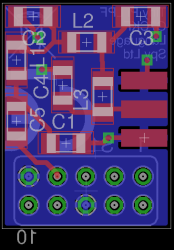
1: A low-pass filter. The Pi produces a square wave which contains a lot of harmonics. If I'm transmitting on 14 MHz then I'm also transmitting something on 28 MHz, 42 MHz, 56 MHz, and so on. This has the potential to cause interference, and bring the UK radio regulator OFCOM to my door. I therefore need a low-pass filter, an LC network designed to reject these higher frequency harmonics. To that end I've produced some prototype boards for a tiny 15mmx20mm Raspberry Pi expansion board containing a 7-pole LPF and an SMA socket. Incidentally I think this may be one of the smallest Raspberry Pi add-on boards produced. See this project log for more details of the LPF. I will eventually offer this tiny LPF board as a kit alongside my larger LPF kits.
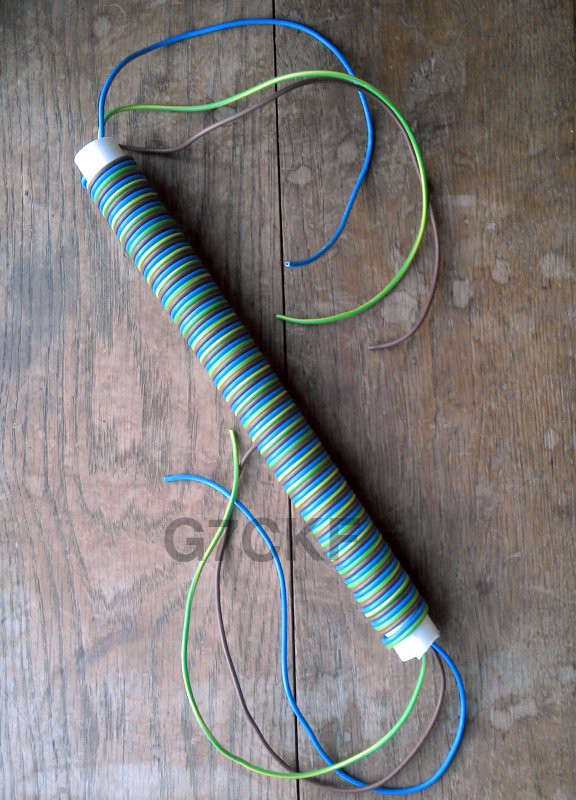
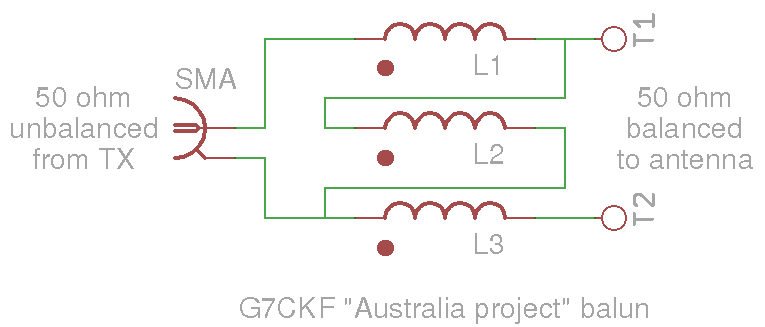
2: A feeder and balun. A typical transmitter will send its RF to the antenna along a length of co-axial cable. Co-ax is good stuff, but even the best has a loss associated with it. For every metre of cable I lose a little bit of power, and when I only have 10mW I need all of it. So in this case I won't have a feeder, I'll put my Pi Zero up on the antenna at the feedpoint so none of my RF is lost. There's another component involved in getting the RF to the antenna, a balun. The antenna feed is balanced, it expects to see an electrically symmetrical feed. Sadly what comes out of the filter isn't balanced, it's just one wire with the RF on it, and earth. So I need a balun, a transformer to ensure correct matching between filter and antenna with no loss of RF. I originally expected my balun to be wound on a small ferrite ring, but as you can see in this project log showing the balun design and this project log showing my completed balun, I went for an air cored design.
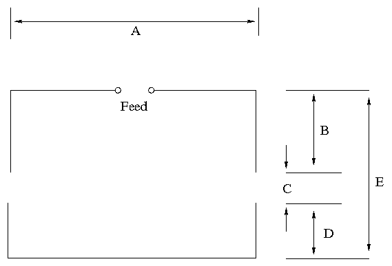
3: An antenna. I will be using the 20m (14 MHz) amateur band, as it is one of the bands most suited to long distance work. 20m refers to the wavelength, so an antenna with two 1/4 wavelength elements can be in the region of 10 metres wide. I will be creating a beam antenna to try to focus my RF power and provide a bit of gain, so in addition my antenna can be several metres long. At the moment the design which has most favour for me is the Moxon, a two-element beam with the ends of the elements folded at right angles to save some space. There are Moxon designs that use fibreglass fishing poles for a reasonable price and weight. You can see the calculated dimensions of my 20m Moxon in this project log.
When I have these three components assembled, I will put my antenna as high up as I can, select the right bearing for Australia from a Great Circle map, run the WSPR software, and wait for reception reports on the internet. The propagation should pick up as we go into spring, so by summer I should know whether my project has achieved its aim.
 Jenny List


Hi Jenny,
thanks for this inspiring project. I just used a PiZero with your 20m filter design and my 90cm diameter magnetic loop (will make this a hackaday project). Got a spot from Finland (over 1700Km from my QTH in Scotland) - and this with the loop sitting indoors in one of our rooms upstairs.
73 de MM0DQM, Mark