WiFi Socket prototype based on SUPLA and ESP8266
ESP8266 and Relay Control Using Smartphone
ESP8266 & SUPLA
ESP8266 & SUPLA
To make the experience fit your profile, pick a username and tell us what interests you.
We found and based on your interests.
WiFi Socket prototype based on SUPLA and ESP8266
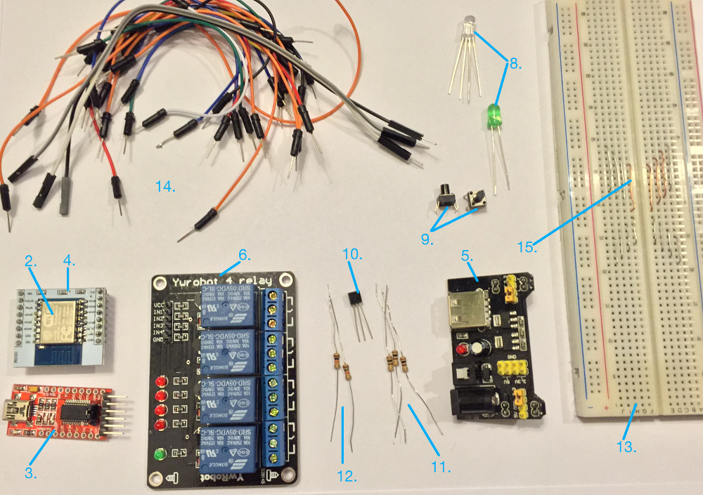
What will we need?
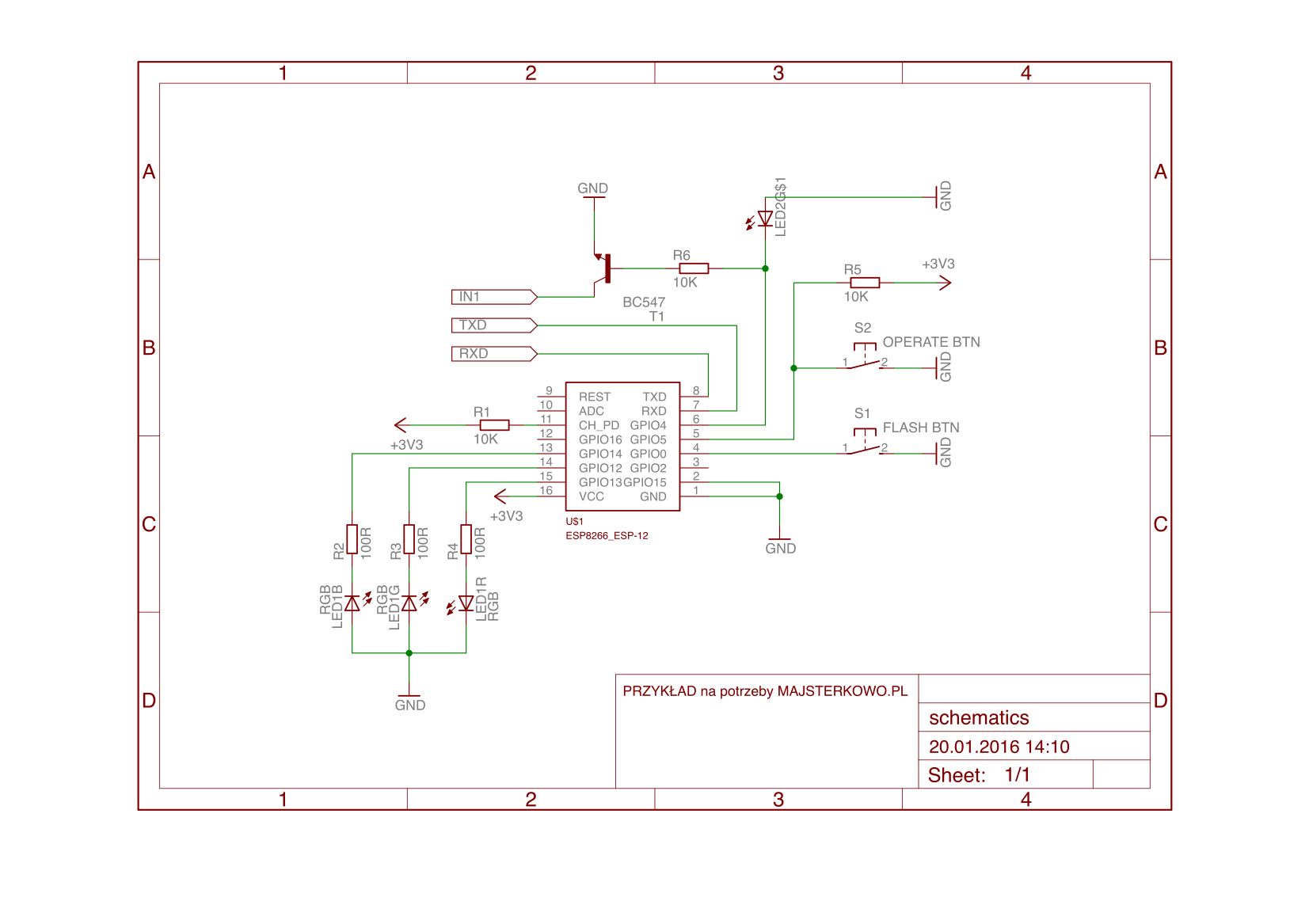
Do not forget to connect the ESP module TXD pin to the USB-Serial converter RXD pin, and the ESP module RXD pin to the USB-Serial converter TXD pin. “IN1” must be connected to the relay module.


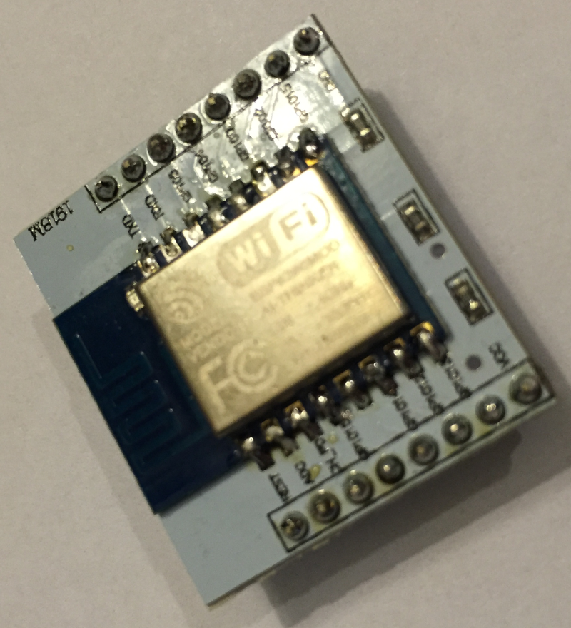
Solder the ESP8266-12 module to the PCB adapter

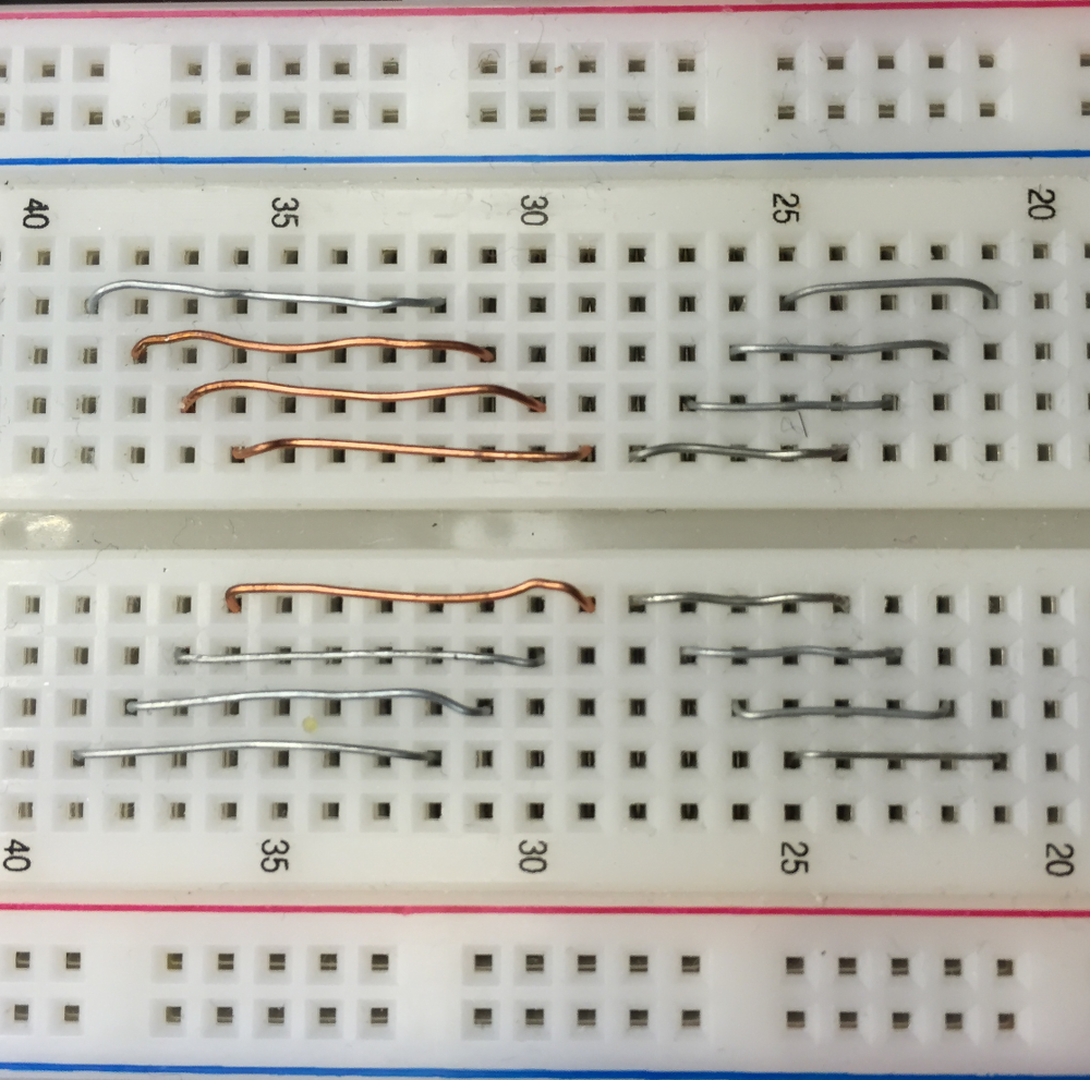
With a thin wire make hookups for easier module pin connections.

Create an account to leave a comment. Already have an account? Log In.
Become a member to follow this project and never miss any updates