-
1Step 1
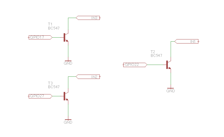
At the beginning we need to hook up the relay module to Raspberry. The software used by me is default set to operate 3 relays, however, if we do not have such, we can also use one and leave the other out. The relays can be connected to electric locks opening wickets/doors or to the gate controller. Relays functions as well as each relay operation time can be later changed at cloud.supla.org. Below you can find the scheme on how to connect Raspberry PI with the relay module.
![]()
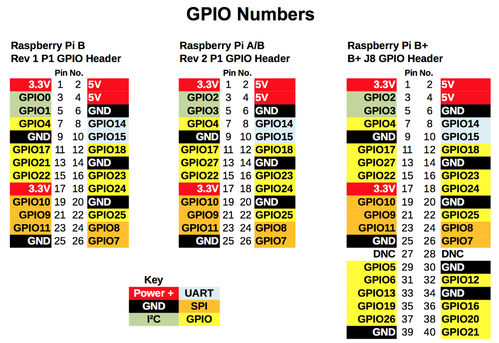
Raspberry PINs specification (source: http://raspi.tv/2014/rpi-gpio-quick-reference-updated-for-Raspberry-pi-b)
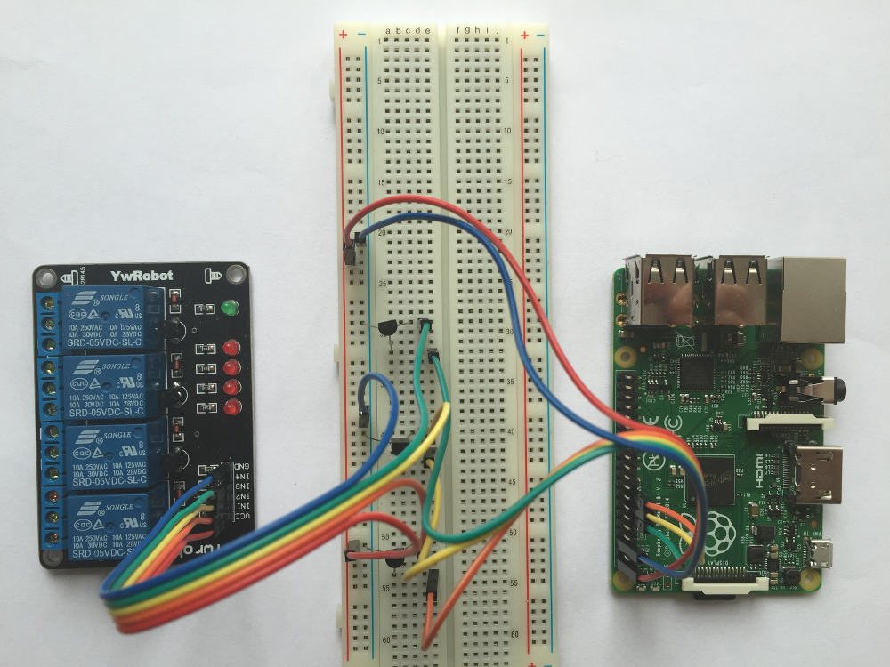
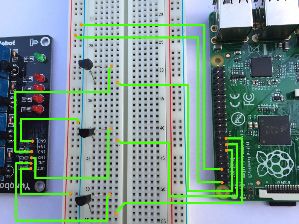
Hook up on the breadboard.![]()
![]()
![]()
-
2Step 2
In order to have it all working correctly, we need to start a free account on
https://cloud.supla.org/account/create
When we sign in and logon, we need to read location settings which are required in Step 3 as well as access identifier settings required in Step4 below
-
3Step 3
Now we need to prepare the SD card (I have been working on a Windows 7 based PC).
- Download and unzip SD card image https://www.supla.org/download/rbpiext01.zip
- Insert the SD card into your computer’s card reader.
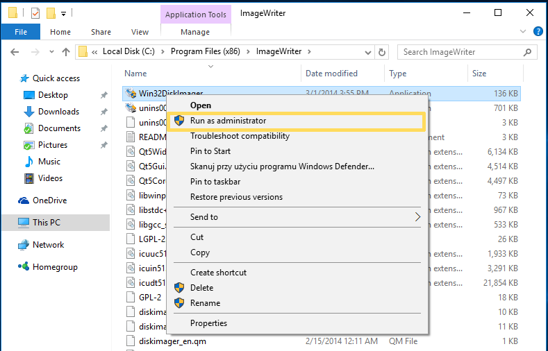
- Using Administrator account run the DiskImager program. You can download it from: http://sourceforge.net/projects/win32diskimager/
![]()
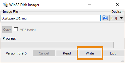
- Point the downloaded and unzipped file in the „Image File” field and select the device (the disc with SD card) and click “Save”.
![]()
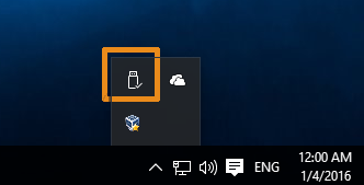
- We can now safely remove the card with the „Safely remove hardware and eject media” tool, remove it and place it back again in the reader
![]()
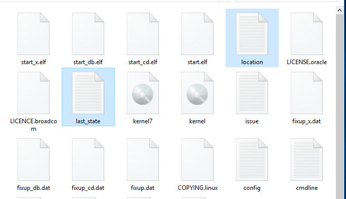
- We need to open the disc labeled on the SD card as „boot” partition
![]()
- Open the location.txt file and enter the location data read from https://cloud.supla.org. The most recent connection status can be read in the file last_state.txt, e.g. an invalid password’s information will be saved here
![]()
- We can now safely remove the card with the „Safely remove hardware and eject media” tool, remove it and place in the Raspberry PI SD card driver
- Connect Raspberry PI to LAN and turn the device on (you can also reconfigure it to connect with network via WiFi)
- Raspberry should be included on the list of devices in cloud.supla.org when properly launched
![]()
-
4Step 4
Smartphone configuration.
First of all, you need to download the application on your phone from AppStore or Google Play. Application is free of charge.
iOS: https://itunes.apple.com/us/app/supla/id996384706?l=en&ls=1&mt=8
Android: https://play.google.com/store/apps/details?id=org.supla.android
Install and start the application.
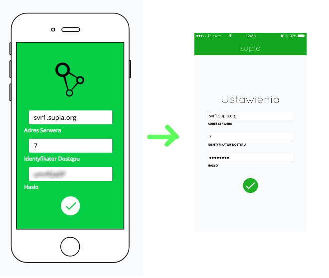
Right after you start it, a window will appear, where all the settings from cloud.supla.org must be entered.
![]()
Ready!
Further information:
Configuration: /etc/supla-dev/supla.cfg
Relay: GPIO27, GPIO22, GPIO17
Ports of entry (e.g. opening sensor): GPIO24, GPIO23, GPIO18. When setting each port in a high status, we can inform the system, whether the doors/wicket/gate are locked.
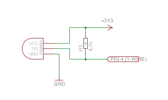
Temperature sensor 1-WIRE: DS18B20
Temperature sensor wiring diagram:
![]()
When you connect the sensor, you only need to restart the Raspberry to have it detected and visible on your Smartphone. You can parallel connect a few temperature sensors at once.


Discussions
Become a Hackaday.io Member
Create an account to leave a comment. Already have an account? Log In.