 Colin O'Flynn
-
1Step 1
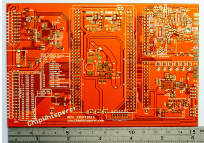
Decide on your desired capture hardware. This example will use the full-blown Spartan 6 LX25 example. Starting with the blank PCBs:
![]()
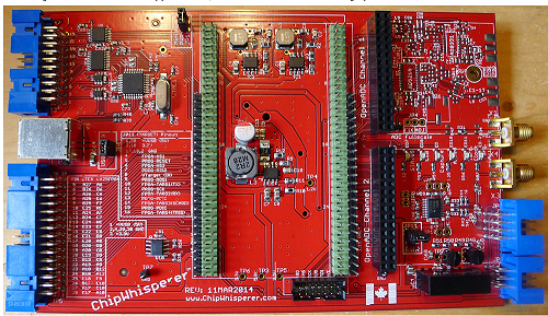
Mount parts as detailed in the wiki page, giving you something like this:
![]()
Powering the board up should allow you to test the power supply sections. You can also program the AVR-USB at this point as detailed at http://www.newae.com/sidechannel/cwdocs/hwcapturerev2.html [NB: the hackaday.io instructions web link settings aren't working for me often, so apologies on the lack of clickable links].
-
2Step 2
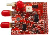
You can then decide to mount the parts in the OpenADC section, or build a separate OpenADC PCB. My examples always use a separate PCB, but the exact same circuitry is placed onto the PCB itself. See detailed build instructions on the OpenADC Wiki [link: https://www.assembla.com/spaces/openadc/wiki/Building_the_OpenADC], also adding a 2x30 pin male header to mate with the 2x30 female header on the ChipWhisperer baseboard.
![]()
The full BOM for the OpenADC is available at http://www.assembla.com/spaces/openadc/documents/aCyIcwKlur4RUaacwqjQYw/download/aCyIcwKlur4RUaacwqjQYw
-
3Step 3
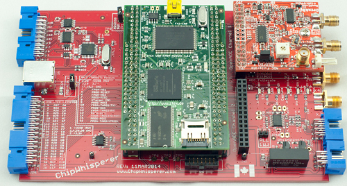
Add the ZTEX LX25 FPGA Module, which with the OpenADC, should now look like this, using a 0.375" hex stand-off with 4-40 screws for the OpenADC:
![]()
-
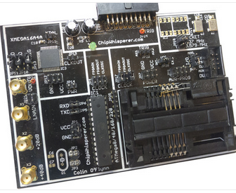
4Step 4
Decide on a target module - if it's the multi-target board, see the documentation and build one up as detailed on the wiki [link: https://www.assembla.com/wiki/show/chipwhisperer/Multi-Target_Component_Assembly_Guide]:
![]()
-
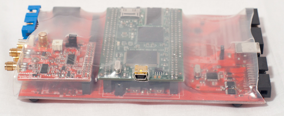
5Step 5
Optional (see #6 too, option of hard or soft enclosure): Use a 12" piece of 3" clear diameter heat shrink tubing to cover the board, the cut out the USB-mini connector with an X-acto knife, and mount rubber bumpers such as Digikey part # SJ5748-0-ND on the bottom:
![]()
-
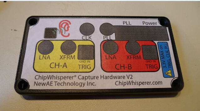
6Step 6
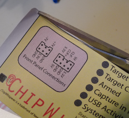
Optional (see #5, option of hard or soft enclosure): Make an enclosure out of a Hammond 1455N1602 case (Digikey part # HM980-ND). This case has plastic end panels which you can easily modify with a hot knife, file, etc. For the front panel you can print out the label in 1-1 scale and use as a template. My assumption is most people will be creating them manually with a knife/file/nibbler type tool, so iteratively checking the fit will provide the best results, as the template is centred 'by eye', and it's also not 100% accurate.
![]()
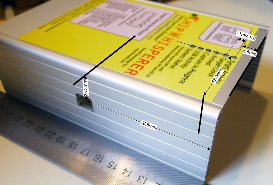
Alternatively you could 3D print the end panels, although as I don't have a 3-D printer have never bothered to create a model for doing this. If you create one please add it to the project! Dimensions for the front panel are given below, I used a 1/8" end mill on my machine for this. You can avoid the holes needed for the 2nd channel most likely, as currently only channel A is used.
![]()
And for the rear panel:
![]()
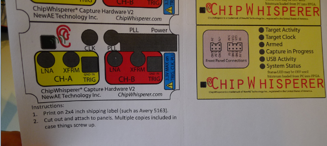
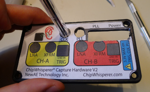
Labels are available in the GIT repository [link: https://www.assembla.com/code/chipwhisperer/git/nodes/master/hardware/capture/chipwhisperer-rev2/mechanical]. The front-panel label can be printed on a standard 2x4 address label (such as Avery 5163/8163), and you can use one as a template for modifying the front panel. A short version of the top label is also available, which is included in the default PDF of the 'label prints':
![]()
You'll have to trim labels as appropriate:
![]()
For the full-size top label, you'll have to print on a full-sheet label and cut it down. When the plastic front panel is on, the label should butt up to the edge of the plastic front panel:
![]()
The front panel label can be cut and punched to clear holes:
![]()
Next, the objective is to modify the aluminum enclosure as follows:
![]()
Drill 6 holes in the top using a #33 bit (or try a 7/64" bit if you lack a numbered set), and insert six PLP2-250 light pipes into the holes. You might need to epoxy the light pipes in place if your holes are slightly larger than intended (hand-held drilling, dull bit, etc).
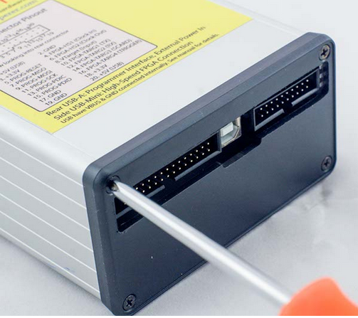
The mini-USB goes through the side of the case. You can cut out a 12x15mm rectangle, or just drill a large hole at that location.
Note you don't modify the 'belly plate' in this design. This was done to allow you to remove the 'belly plate' during operation and modify jumper settings without needing to worry about breaking off the light pipes, which might happen if they were connected to the belly plate.
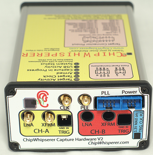
Now you can assemble to a complete product:
![]()
![]()
-
7Step 7
Make a 20-pin ribbon cable to connect the ChipWhisperer to the target, also get a SMA cable and connect the boards up:
![]()
-
8Step 8
Install software using the latest release version. See the installation documentation, along with the latest release page.
-
9Step 9
Start following some of the tutorials [link: http://www.newae.com/sidechannel/cwdocs]! If you have trouble check out the forum at https://www.newae.com/forum
ChipWhisperer®: Security Research
ChipWhisperer laughs at your AES-256 implementation. But it laughs with you, not at you.


Discussions
Become a Hackaday.io Member
Create an account to leave a comment. Already have an account? Log In.