I have made the PCB files! For now, I have removed the ESP8266, because I want to get this thing up and running. Before I send them off, I want to wait for the passives for the OLED, so I can test things out on my spare screen.
The routing is probably awful, but this is the first PCB I designed.Also, the pads for the 6mm tact buttons extend to the edge of the board - let's see if they come out working :S
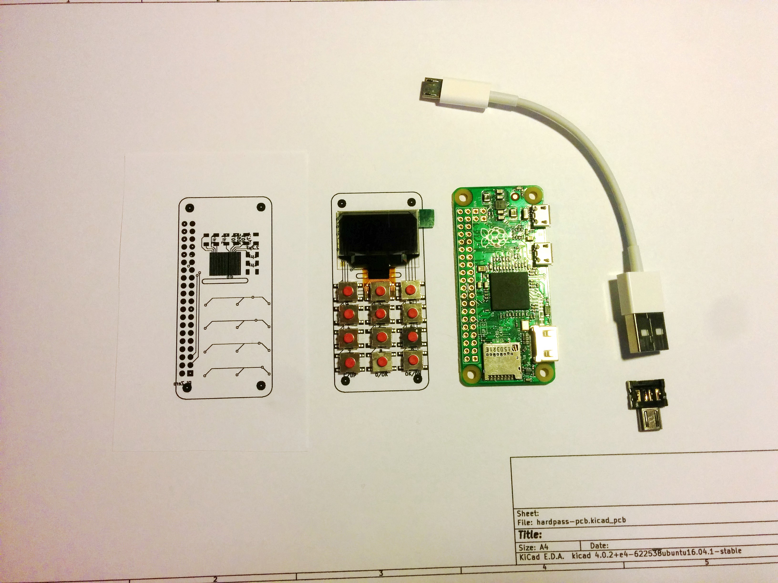
When I tried the fit of the components I have already on a paper printout, I noticed the header pins were a little off in respect to the Pi.
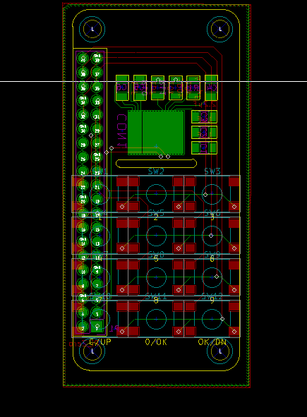
Soldering the 5mm pitch of the OLED will be a challenge, but this 20 pin version of the screen is the only one that can be centered on the board (the pads of the header connector are in the way with the 30 pin version).
Discussions
Become a Hackaday.io Member
Create an account to leave a comment. Already have an account? Log In.
This is brilliant. Great work man!
Are you sure? yes | no