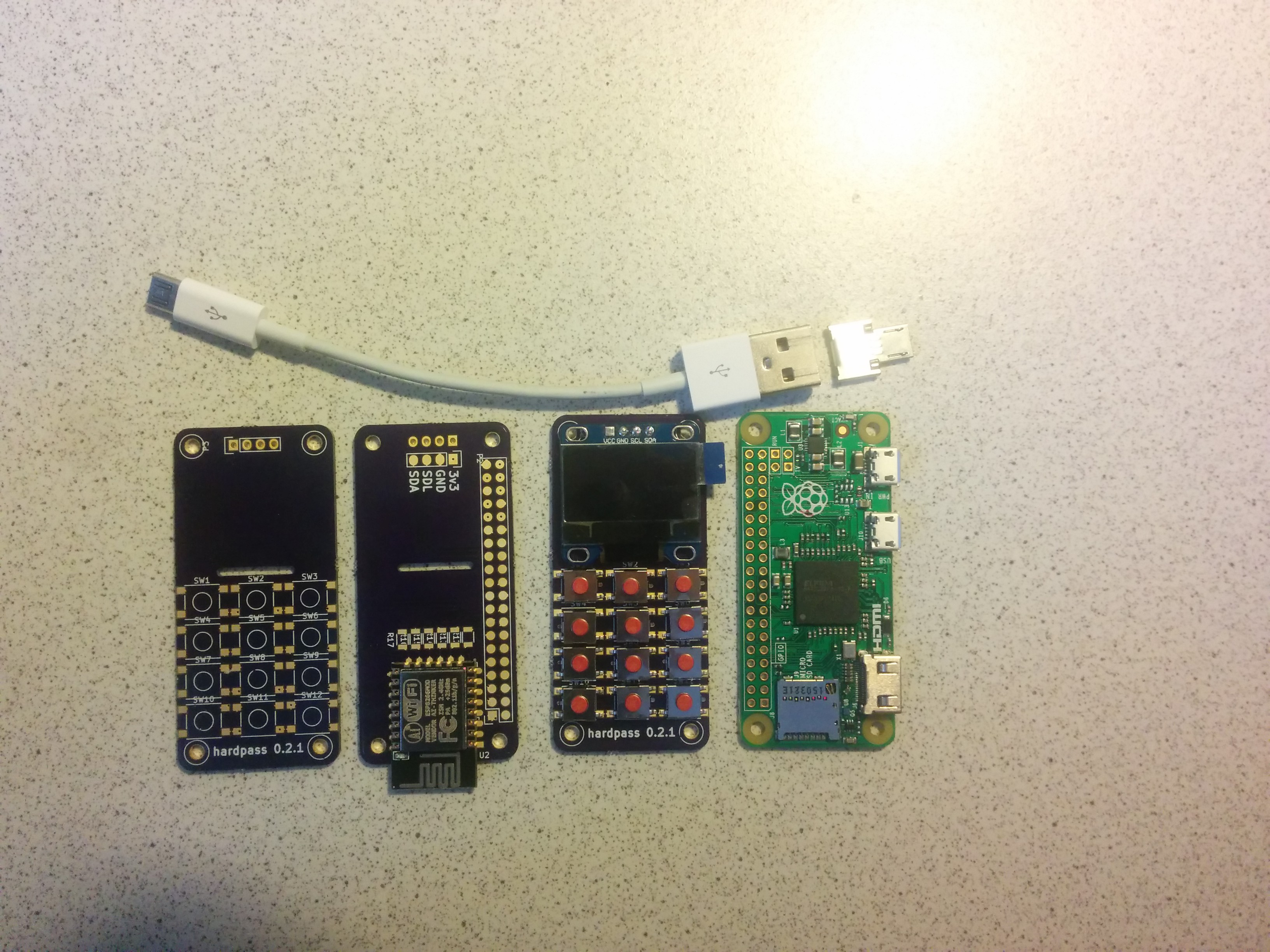
I shelfed the project for some time, but recently I have been working on it again. The 20-pin OLEDs aren't available on AliExpress any more (the last seller who claimed to have them didn't have them).
So I modified the PCB to take the premade assemblies / modules. (I do plan on modifying the PCB to take 30 pin OLEDs)
I also finally ordered some prototype boards from OSHPark (really streamlined ordering process, just upload the pcbnew-file)
On the top of the back side you see those solder pads under the screen header: While many OLED modules have 4 pins, all of them have different pinouts. I plan on soldering jumper wires to set the correct connections.
On this picture you can see all the components involved (except the .1" header and some resistors, which hvaen't arrived yet)

Discussions
Become a Hackaday.io Member
Create an account to leave a comment. Already have an account? Log In.
Nice board design! We look foward to future updates.
Are you sure? yes | no
To be honest, it isn't. It was the first PCB I designed (in KiCad and ever). Some traces are probably too thin, the header is not perfectly aligned and the 3v3 polyfill is <1mm thick at its thinnest point.
Thanks for the jelly beans though -- nice touch!
Are you sure? yes | no
@gir Impressive nonetheless for your first PCB! One of our engineers, Jenner, created Kicad libraries and templates that may help in the future: http://wickerbox.net/wickerlib.html
Also, Contenxtual Electronics by @chrisgammell: https://contextualelectronics.com/learning/getting-to-blinky-4-0/
Are you sure? yes | no