Sergey
-
Draft design for two boards (top/bottom)
03/19/2016 at 23:05 • 0 commentsOK,
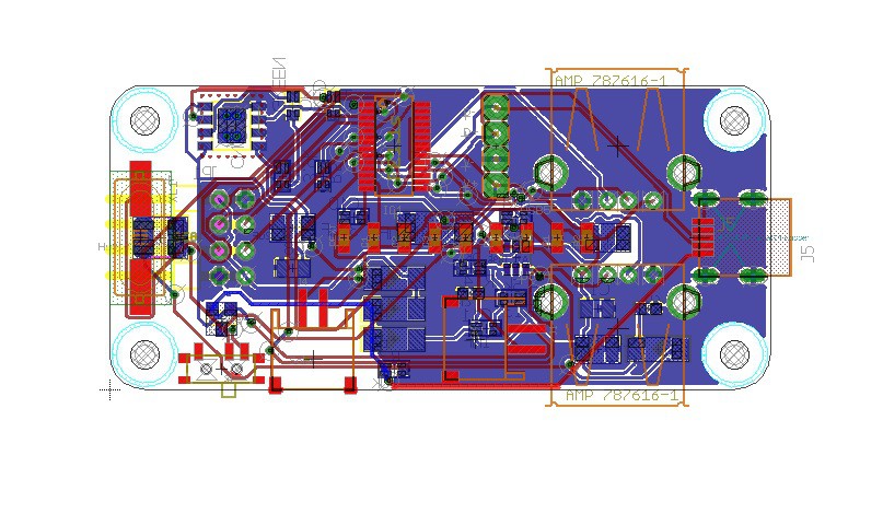
Designed bottom hat - Power board (Modified LiPo Rider and modified USB hub) with a place I beleive for small LiPo battery
![]()
Two USB ports. mini USB for charging, a header for additional 2 ports, a battery connector and a connector for solar panel, header for connecting to Raspberry USB and Power solder pads.
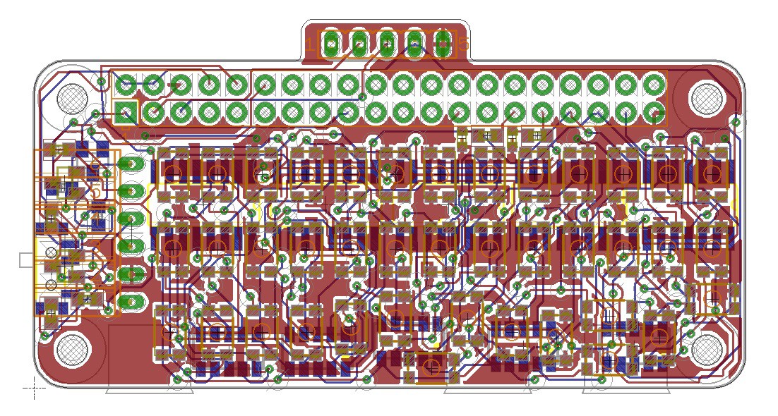
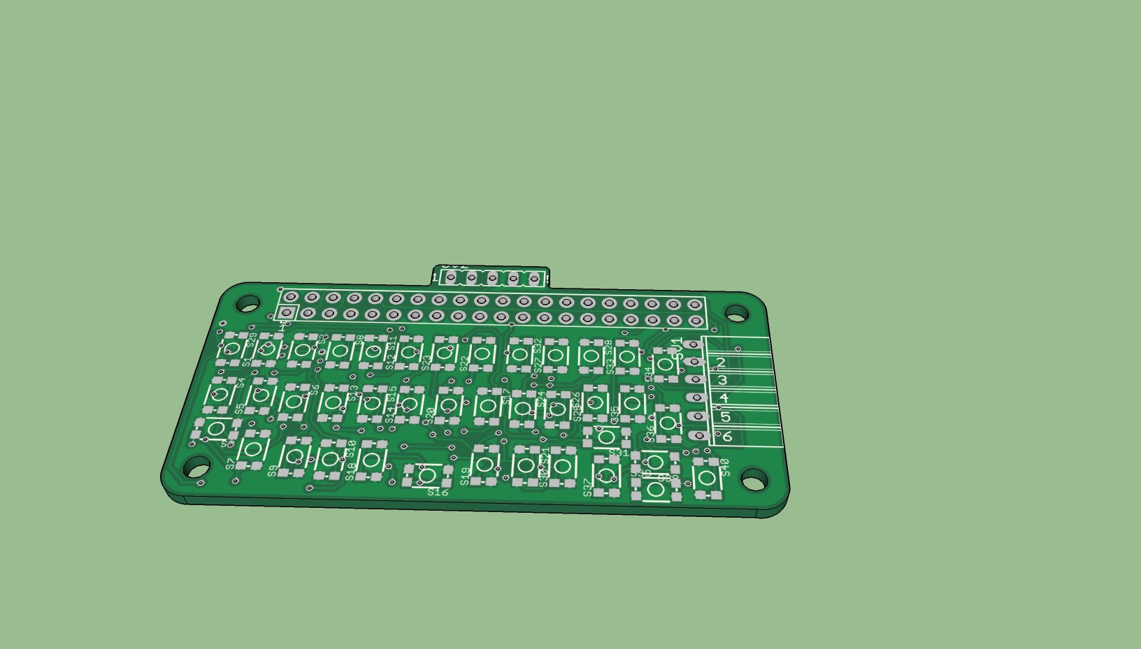
Re-designed Qwerty, top hat
![]()
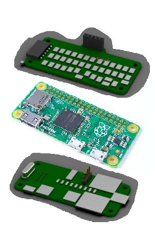
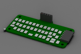
Future Modular design (plus Battery), yep PiZero Sandwich :)
![]()
-
Design considerations
03/16/2016 at 15:00 • 0 commentsHi,
I'm currently re-wiring the Pi Zero Qwerty Hat board, with Arduino adapters on the left side, because Pi's Serial is on the left side of the GPIO header.
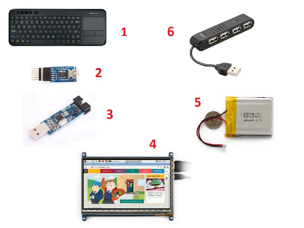
In the meantime, I need to decide what are going to be components of my Pocket Zero device. I want it to be portable and as small as possible at the same time powerfull.
![]()
So, for good and portable Arduino programming, what do we need?
- Full Keyboard (it's somewhat complicated on touch keyboards)
- FTDI/Serial connection
- Chip Programming device (preferably, to work with bare-bone chips)
- A monitor
- Power for our Pi (preferably with charging)
- USB hub (which in some case could be all we need)
In a signle hat we cannot fit everything. So I need to group them by priority.
- FTDI/Serial First - if you have it you can already do anything you need with help of your Smartphone
- Power. If you have power - you don't need to bother how to power your Pi and Arduino
- USB Hub. It's easier to connect your smartphone or Bluetooth or WiFi, or even Arudino via stand-alone FTDI
- Keyboard. I feel like real programming cannot be done with reduced or touch keyboard
Montior and ASP Kind of nice to have.
Now an interesting facts:
- If you combine Power+USBHub, you don't need FTDI and you can live without Keyboard
- If you add FTDI and keyboard it's a perfect match.
But there simply not that much space on a Zero hat to put them all together.
So, my thought right now is the following:
- Bottom hat. Power (based on LiPo Rider) + USB hub (reduced to 2 or 3 ports). This hat doesn't need to use GPIO header
- Top hat. Keyboard + FTDI/serial (this is already in Eagle and under testing)
-
Serial levels converter test
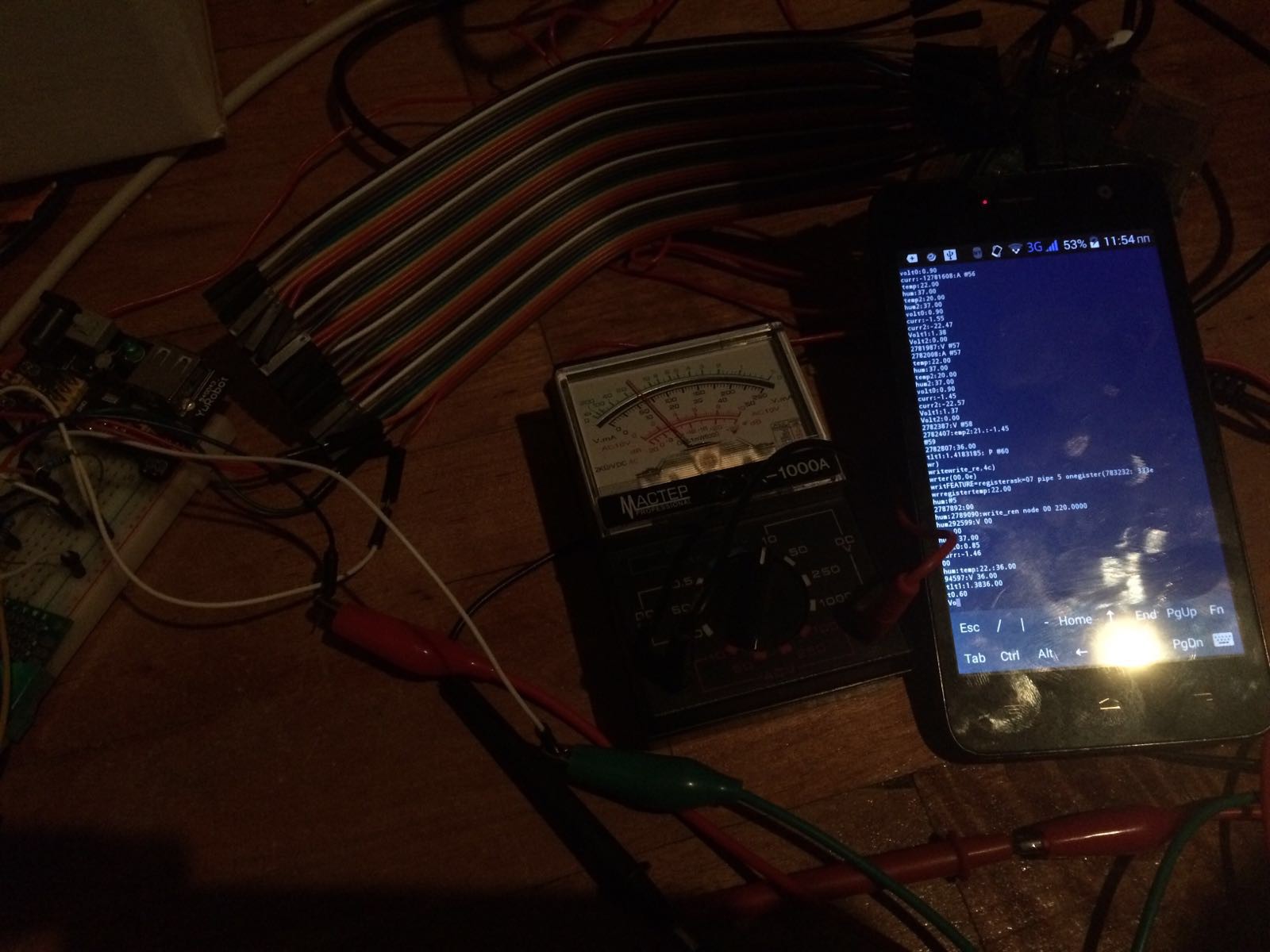
03/11/2016 at 09:54 • 0 commentsOk, so test with 5volt arduino succeeded. I was able to connect it to Raspberri Pi Serial and receive output. This is a temperature station powered by 4 AAA batteries which is sending info to the base station via nRF24L01 and it logs some debug output to the serial port. I was able to connect my phone to the raspberry, then login using SSH and listen to the com port using "screen /dev/ttyAMA0 115200" command. Voltmeter is for checking that Raspberry's side is staying at 3.3volts. I used BSS138 FETs, exactly how in this Adafruits converter
![]()
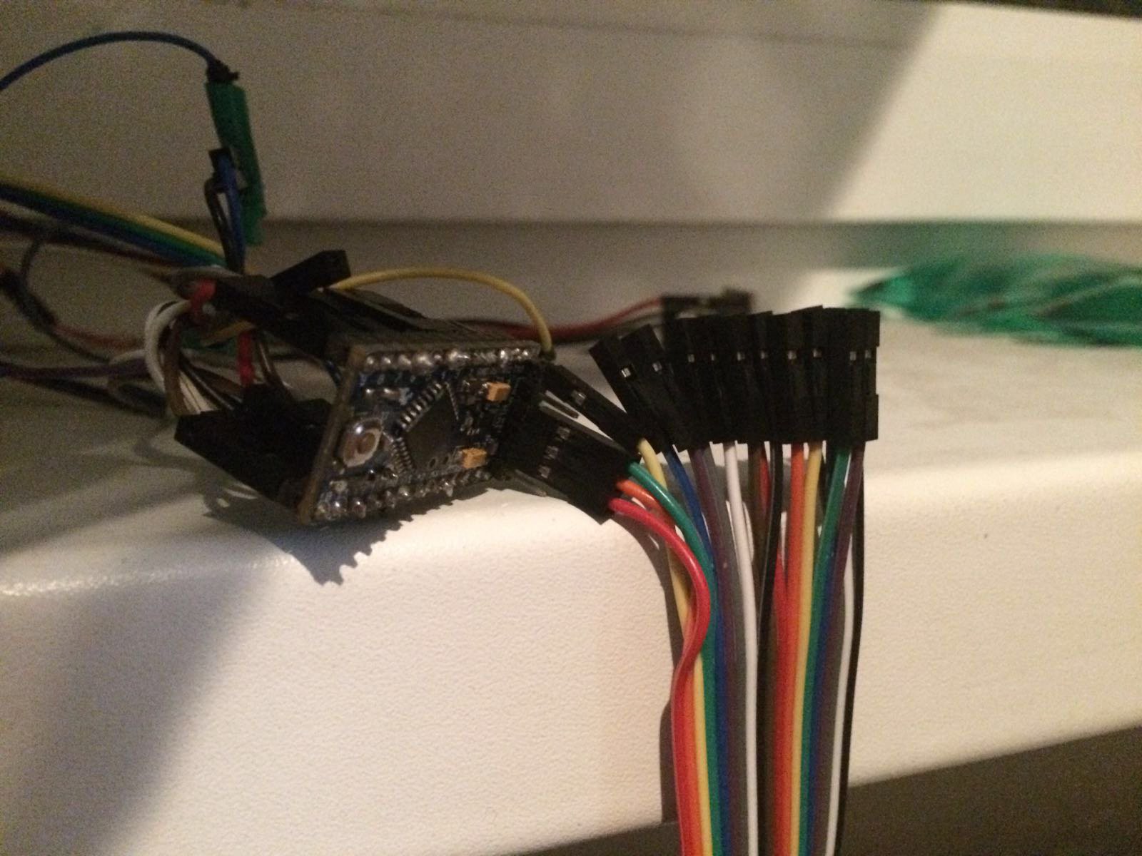
This is the Arduino side (sorry for messed up setup - This Pro Mini is currently doing her job and I didn't want to distract her :))
![]()
-
No Zero, but I'll continue
03/04/2016 at 15:05 • 0 commentsSadly no free Pi Zero for me, I think probably because I'm in Russia and wouldn't get it soon anyway ;)
I'm currently wiring everything for level conversion test of Arduino <-> Pi Zero serial communications. I already confirmed Adafruit's setup works perfectly, but I forgot that I would need reset pin (so additional conversion elements on the board:() and I would need also a power switch 5v-3.3v for Arduino connector. Or a jumper.
Do you have an idea where to put it? :)
![]()
I'll have more updates soon. When I figure our what to do with that jumper, ha-ha
-
Another board refactoring
02/29/2016 at 12:50 • 1 commentSo, I was able to place level convertion circuit to protect Raspberry Pi from 5volt arduinos. And some LEDs to help with keyboard usage. It would be great to be able to see feedback from using Raspberry completely without a screen. For example you can program some script to be launched using the hotkey and a result can be displayed via LED. For example: Ctrl+U+1 to upload some code to Arduino and blink green led once if success.
![]()
P.S. Probably will need to refactor again, to add 5v-3.3v switch for Arduino pins.
-
PoC with USB keyboard
02/29/2016 at 11:03 • 0 commentsHi, here is viedo of PoC with USB connected keyboard being used with smartphone acting like a Raspberry Pi screen.
Some explanations are probably necessary. I'm using the following software setup:
- x11vnc server in autostart for xserver. Installed via the following convenient script (http://simplesi.net/auto-install-x11vnc/)
- Raspberry configured to autoboot into the x session
- Console X session screen resolution changed (probably need to be changed to soemthing else)
- terminal window automatically opened on X server startup and screen command executed, so that you can SSH into the console session and use the keyboard
- /etc/dhcpcd.conf modified to allow static IP for usb0 netowrk adaptor
- Arduino IDE installed
-
Refactoring again
02/26/2016 at 09:40 • 0 commentsAnother refactoring to the PCB is required. I haven't ordered it yet, because I knew somethign like this would be required.
Since I'm new to Raspberry Pi, I didn't know that its levels are at 3.3volts, so by directly attaching 5volt Arduino I could damage the thing.
So, I'm going to add level converter circuit to the board luckily it's not huge and required only for RX and TX signals.
Here is an example of how it is being used (it's the one Adafruit has in their store https://www.adafruit.com/products/757)
http://www.deanmao.com/2012/08/10/uploading-sketches-to-the-arduino-on-the-pi/
Looks like same thing is required for ISP programming, although maybe bare Atmega chip can be programmed using 3.3 volts.
This is something I'm going to test.
P.S. Also will try to post a video today about using keyboard attached to the console session in other remotely connected sessions.
-
Programming connectors
02/24/2016 at 12:46 • 0 commentsSo,
Now that qwerty PCB is ready, looks like I have to adjust it ;)
I need to try something with real raspberry, it's not currently clear if direct serial communication between raspberry and arduino is OK for programming or I need some logic level adjustment circuit.
Also since it's arduino targeted programming Pi Zero hat, it would be nice to add ISP header, looks lik there are some tutorials and this should be possible with raspberry, although again the question is about signal levels. AND about pcb space - I almost don't have it at all.
ToDo - Test real arduino with real raspberry. It would be awesome to win one, in the meantime I have to use someone else's device.
ToDo - With respect to using the keyboard - here is what I'll need to do on boot:
- autostart Xserver with x11vnc enabled and with low resolution (suited for smartphone display)
- auto-launch xterminal in the GUI session with screen command
This way it doesn't matter how you are connecting:
- Via VNC client - you'll see the console X session and will be able to use qwerty directly
- Via SSH client - you'll need to login into the multiuser screen session, again you'll be able to use qwerty in this case (already tested)
Smartphone connection for now is going to be USB, Bluetooth for the future
Big question is power, as usual. I decided not to spend time right now reserching harvesting it from mobile phone, instead let's add battery and charging circuit in between Pi Zero and Qwerty hat
ToDo - Desing battery and charging PiZero hat, there should be a way to remove it completely, because if you have apower source it's necessary for the device itself.
-
Prototype PCB Project completed
02/23/2016 at 22:01 • 0 commentsFinally made it. With help of Eagle autorouter plus some re-wiring. I have a lot of clearence alarms :(
I understand that it should be polished, but at least I can say here it is, it is possible to do this thing.
I know it's going to work because I've researched the following topics
- Using Shift registers for keyboard-like device in raspberry Pi, with help of WiringPi library
- Using SPI OLED monitors with Raspberry and doing 180 degree screen turn in them
- Programmiong Arduino from Raspberry via serial port (tricky in terms of software config, but should work)
- As a backup plan - I can create an expansion board to programm Arduino via ISP port
- As another backup plan - use USB to FTDI convertor (although I'm afraid this board is done, hardly I can squeeze anything onto it)
I still have a lot of questions to answer. I will try to test the concept of using on-board keyaboard while connecting via Mobile phone remotely. And I need to decide what to do with power for Raspberry.
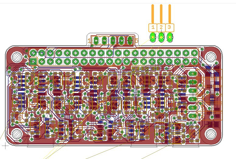
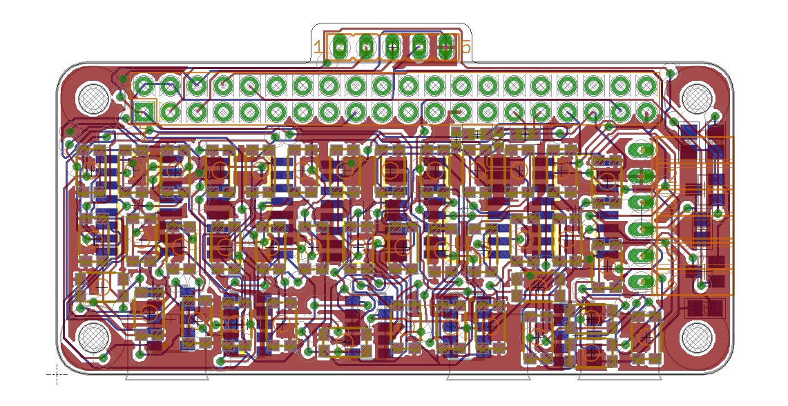
Here are some rederings of the board
![]()
![]()
-
Refactoring N+2
02/19/2016 at 09:29 • 0 commentsOK, routed 32 buttons. BUT, you guys want a Tab, Ctrl, Alt, Numbers, Arrows, don't you? :( I would.
So, trying to route 40 querty keyboard onto Pi Zero Hat. Plus 5 shift registers and 5 resistor arrays.
Kill me... Why autorouter can't do that? I'll spend the rest of contest trying to manually route this tiny beast
Pi ZERO Arduino programming station
Just a PiZero Pocket Computer case, with ability to plug any available Monitor (Component Video, HDMI, LCD) and a keyboard via USB HUB