-
Updates
04/01/2016 at 22:30 • 0 commentsUpdate 1: I'll be adding all the code, eagle and solidworks files once I'm done with project
Update 2: tuning videos/pics will be up soon ✓✓
Preview (terrible quality):
-
Project Logs
04/01/2016 at 22:28 • 0 commentsLog 1: Hardware info
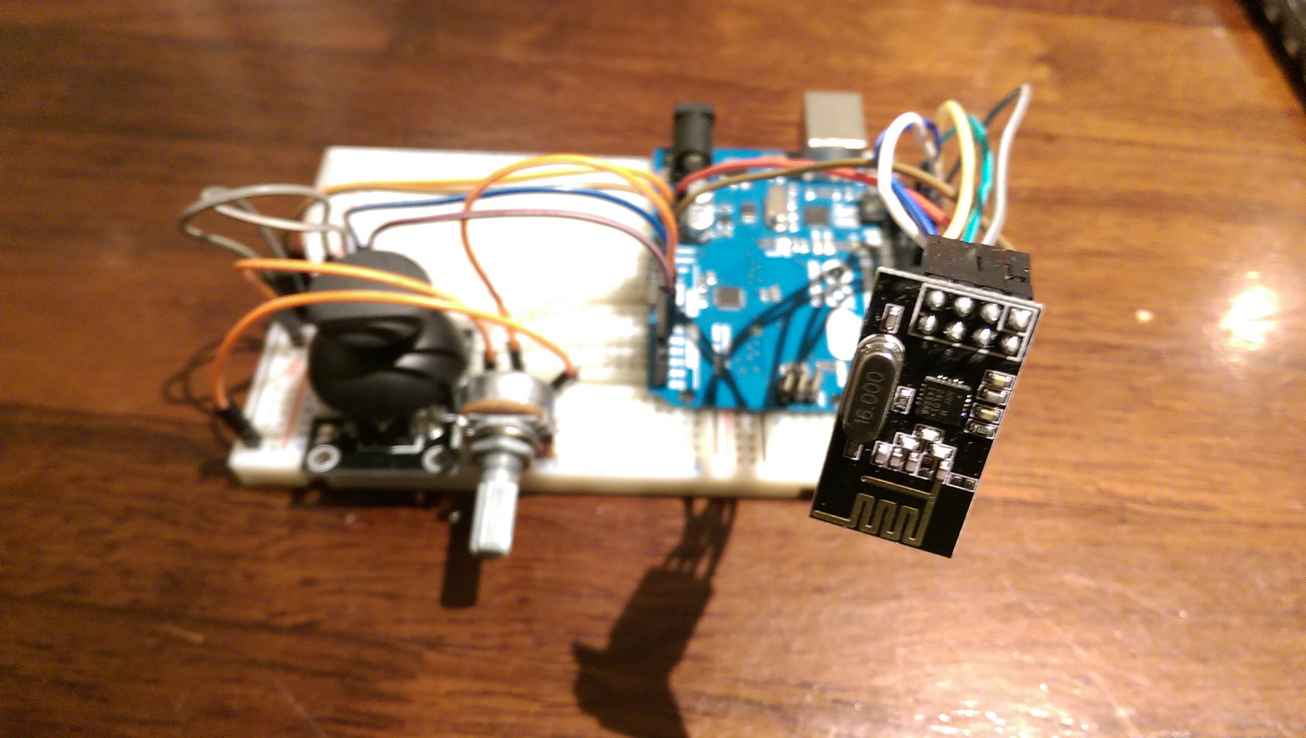
Instead of buying all the mechanical parts to make a quadcopter I was given a frame with the motors, props etc. (however if this works ill use much nicer hardware and make a new one) but no flight controller or remote. For the flight controller I used an MPU6050 accelerometer + gyro and and nRF24L01+ radio all hooked up to an Arduino Nano which would do all the magic. For the transmitter another nRF24L01+ radio a joystick and for the throttle a pot again all centred around the Arduino Nano.
Log 2: How a quadcopter works
The basics of a quadcopter are really easy. A simple way to think about it is this: A quadcopter works by getting two inputs, one from the user and one from itself. The user tells the quadcopter where it wants it to be (move forward/backwards etc) the quadcopter then figures out where it is and changes the speed of the motors in order to achieve this. The following logs explain this in a bit more depth.
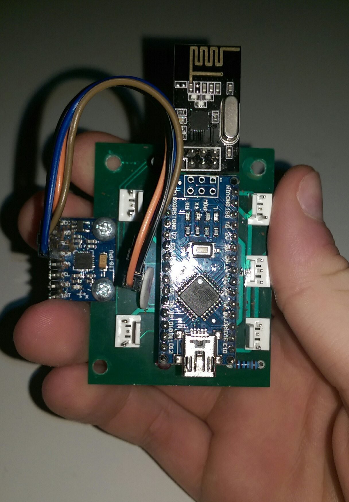
Log 3: Transceiver
The two radios are very simple to use with the nRF library (link the library) however it took me about 3 weeks to get them to work because I fried all four of them and then couldn’t figure out why they weren’t working. The Arduino reads the analog values from the joystick maps them to a range of -20˚ à 20˚ and sends them to the quadcopter, same as the pot (but with a different range). At first I got everything working on breadboard and then I made a PCB for them.
The receiver simply reads an array sent by the transmitter where each element of the array represents a different parameter eg.data[1] = throttle, data[2] = roll and so on.
![Artistic shot of the transmitter prototype]()
And heres a video of us trying making sure everything works (nothing broke ✓)
Log 4: MPU6050
The MPU6050 is a simple 3axis IMU and it works really well. Its got both an accelerometer and a gyroscope and 3 ADC so it can capture all three axes at the same time. There is also a lot of information on how to use them, as well as many well documented libraries, so it seemed like a good choice. In order to get an accurate reading form the IMU both accel + gyro data need to be used. There are two ways of combining them:
- Kalman filter
- Complementary filter
I decided to go with the complementary filter because it’s much easier to implement and it works surprisingly well! I also advise that you calibrate the IMU from time to time and add offsets.
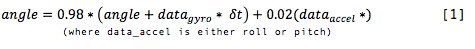
The complementary filter I used is the following:
![]()
where data_g = gyro is the raw gyro data and data_a is the angle calculated only from the accelerometer using the equations below
However once everything works I’ll swap it for a Kalman filter (mainly so I can learn how to implement it for other projects).
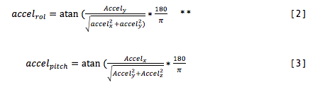
Then to get the roll and pitch I used these equations:
![]()
** this equation doesn’t take gimbal lock into account but the quadcopter will never go more than 20 ˚ so it doesn’t matter.
[2] and [3] are then substituted into [1] and we get a very accurate angle!
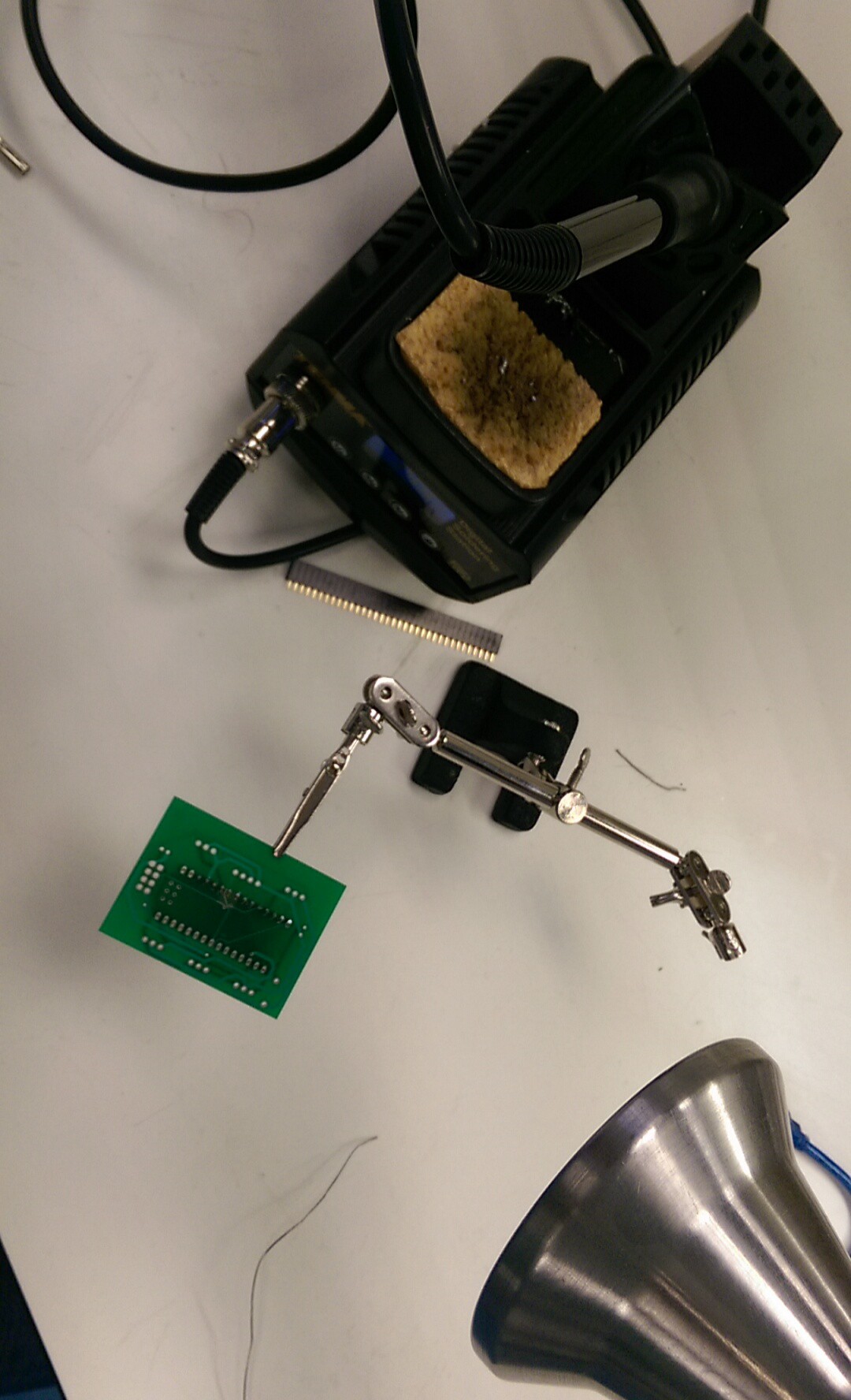
Log 5: PCB
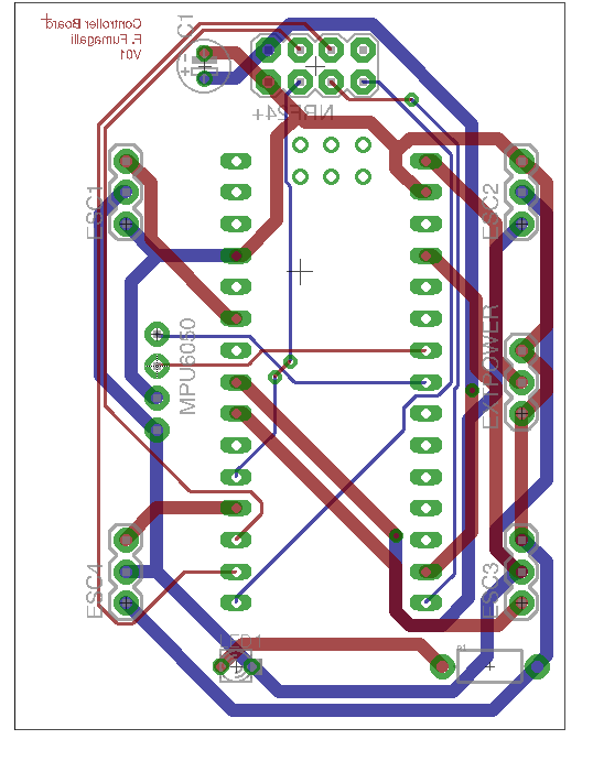
Just to make everything look neater, I made a small PCB for the flight controller. I’ve used headers for everything so I can easily change anything that breaks, or needs updating. I made a mistake when judging how much space the IMU would need and completely forgot it has 8 pins since I’m only using 4, but ill fix all that and add a switch when I print version2.
![Flight controller PCB]()
![]()
![]()
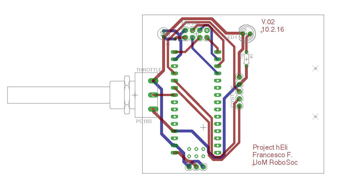
I also made a PCB for the controller, and it turned out to be terrible because its tiny. I'll definitely remake this into a proper controller which I can actually hold with two hands but I haven't done it yet since I don't really need it for now.
![]()
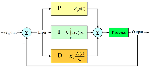
Log 6: Control system
PID, which stands for Proportional Integral Derivative is the standard control system used to control quadcopters. Basically, PID takes two inputs one from the user aka the setpoint – where I want the quad to be (from the radio – in degrees) and and compares it with the angle its actually at (from the IMU, again in degrees) it then calculates an error and outputs a value which it thinks will bring the error to 0 i.e setpoint=imu data. This is an over simplification but there’s loads on information on google. I used the PID_v1 library, but I'm writing my own version for my second year project so I'll be using that one when I've finished it.
![]()
![]()
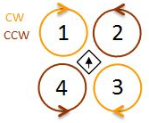
Two PIDs are used one for roll and one for pitch (and probably one for yaw but I don't have that yet). Once the PID gets the data and outputs a value the microcontroller will use these equations to correct the quadcopter.
They’re something along the line of*:
Motor1 = throttle + PID_roll_output - PID_pitch_output
Motor2 = throttle – PID_roll_output - PID_pitch_output
Motor3 = throttle – PID_roll_output + PID_pitch_output
Motor4 = throttle + PID_roll_output + PID_pitch_output
*depending on how the motors are labelled.
Project hΕli
A quadcopter flight controller based on the Arduino nano