Michael O'Brien
-
Hiatus Continues for a Spell
12/01/2014 at 20:19 • 0 commentsHello everyone. I've not forgot or abandoned D-DAQ. If you've been following from when I moved the project to here, you may recall that I've said that this project was near 3 yrs old, though at this time its a few months older than 3 yrs though I digress. It's taken a while because its developed in my free time just like nearly everything on here.
The hiatus is development is simply due to that free time or the definitive lack thereof. Had to pull my transmission this past week to replace a spring and found that the release lever was starting to fatigue and bend. Came across the cause of the fluid leak I've been experiencing as well and have to re-grease a CV joint and it's boot in the very near future as well. Either I spend the money and have a mechanic do it, mind you I rebuilt the engine myself 13K miles ago, and take the time and do the work myself and save a few hundred dollars.
If I can get back to the design work, I can build the power supply subsystem which will be a isolated SEPIC to 2 buck converters. I promise I've not forgotten nor abandoned D-DAQ, but life happens and I'm sorry I haven't made any visible progress in the past few months.
-
OSH Park Manufacturing
09/18/2014 at 23:21 • 0 commentsHello once again. So, most of you who've used OSH Park probably know that they don't officially support plated slots. On my 3rd prototype, I overlapped some drills to see what they'd give me in return and I got plated slots. Taking this into account, I figured I could play around a little and see what results I would get. Now that my proto 4 boards are in, here are some photos of the good and bad.
Original w/ just straight drills
![]()
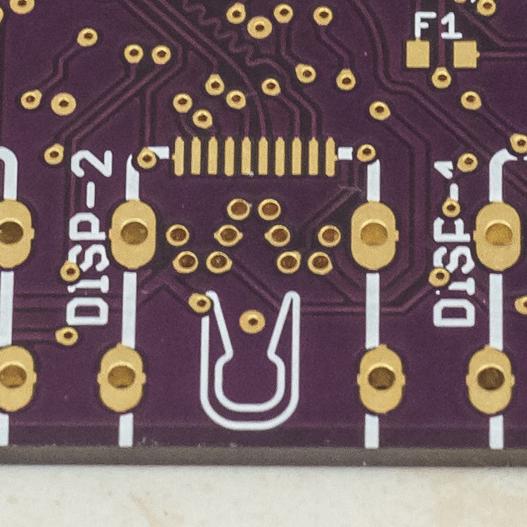
Proto 4 w/ overlapping drills. Angled shot to show full plating.
![]()
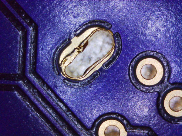
However, not everything is perfect as sometimes the holes aren't drilled out okay.
![]()
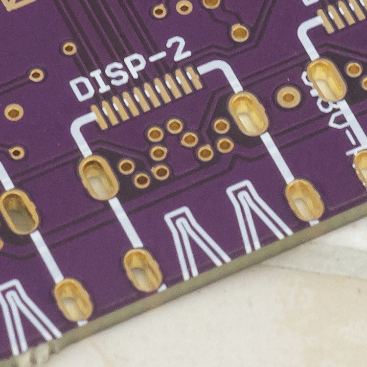
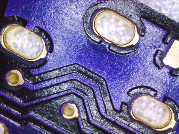
An up close shot on a similar footprint, albeit different location on the same PCB, produced more consistent results, but has a very small annular ring:![]()
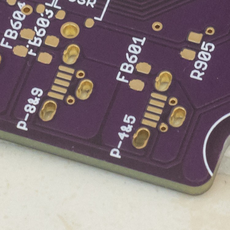
Furthermore, the cut isn't always clean
![]()
It appears that a 0.8-0.9 mm bit was used to do drills/milling for all of the PTHs and though not everything is pretty, it is all electrically sound. I had to go back to my CAM job in Eagle to double check some things. It's stated that milling is ignored, but I've been including it in my dimensions layer for a variety of boards. This is the first time they've actually processed it for manufacturing.
If you wish to see if your design will receive PTH's, I'd suggest trying the same, but have s couple nearby, overlapping drills as a fallback. Also, given the [larger] size of the pads that I adjusted footprints to use, it makes more sense why they were respected now. However, due to the size and repeatability of their attempted PTHs, I'd advise going from a 7 mil annular ring to a 15-20 mil annular ring. Consequently, adjusting my design to account for this would also bring my board into sped for manufacturing by SeeedStudio for lower costs.
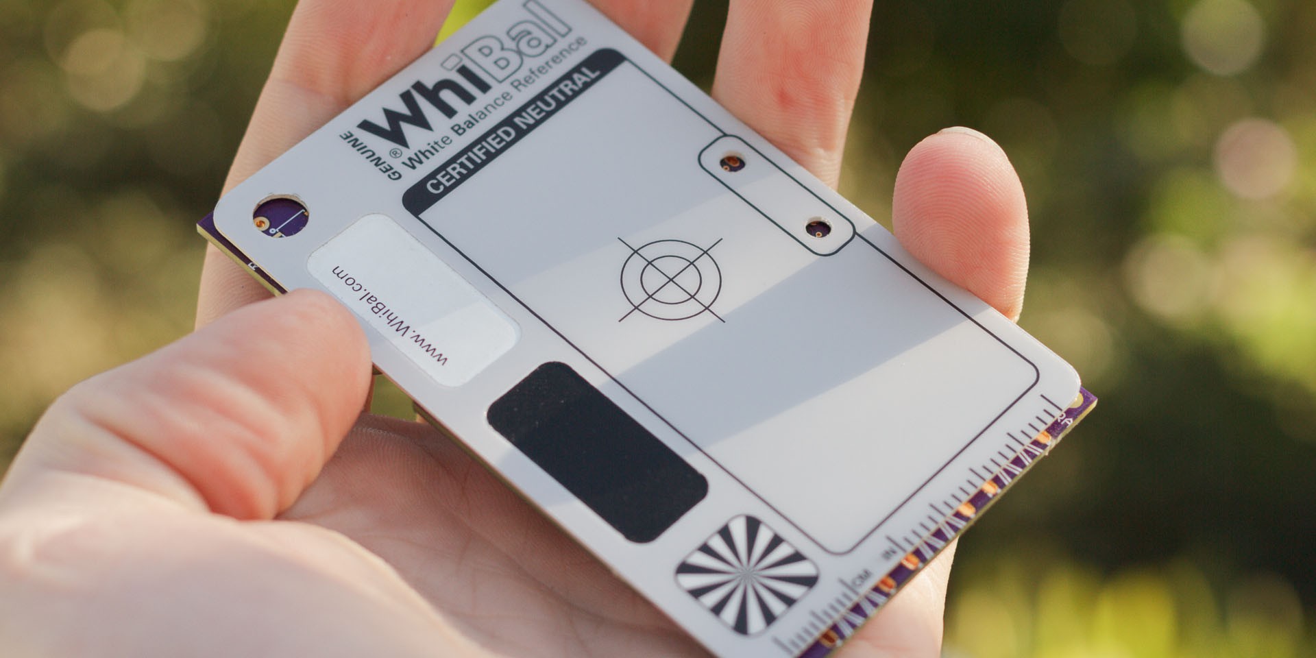
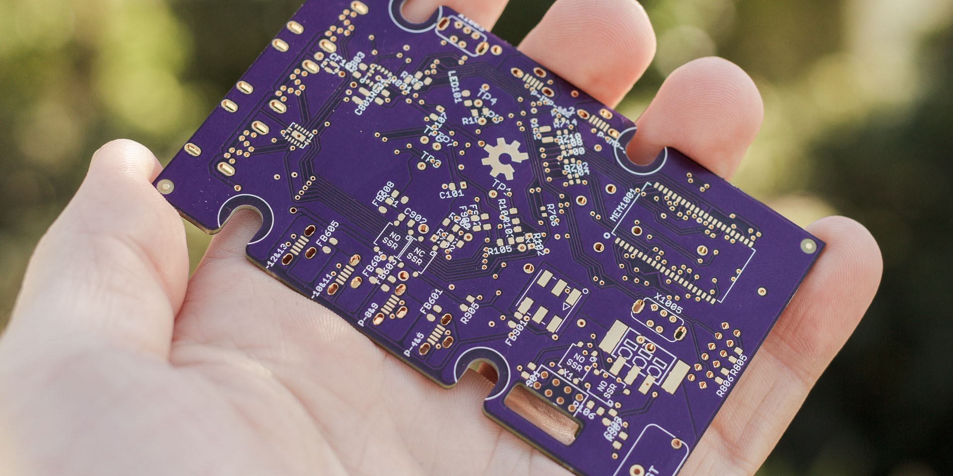
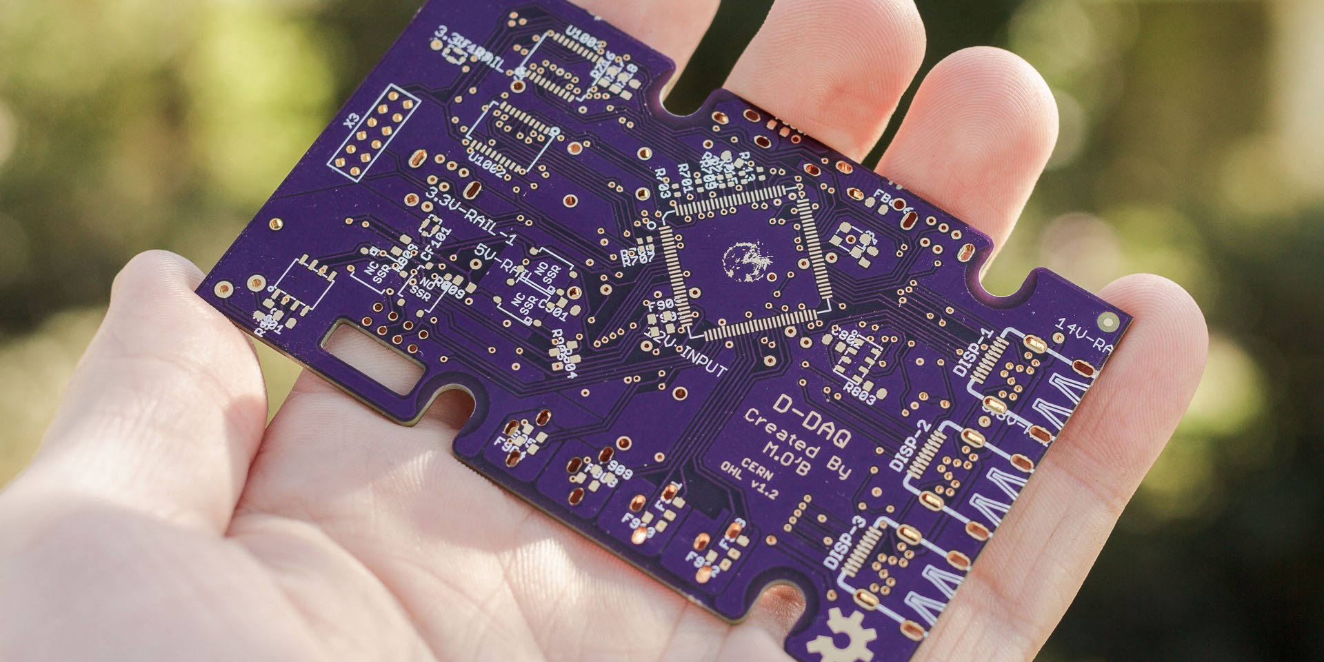
Anyhow, here are front and back shots of Proto 4 of D-DAQ and the credit-card side WhiBal I use for scale comparison:
![]()
Top side
![]()
Bottom side
![]()
-
Proto v4 Arrival & Other News
09/16/2014 at 15:52 • 0 commentsProgress is slow, but I should have the PCB for the 4th revision here tomorrow. I still need to make the power supply end to have a functional device and that has been delayed, but is still in progress. Don't worry, D-DAQ is still kicking, but things may stay on a slower pace due to some changes in my personal life.
Without going into too much detail, I work for a very well known entertainment company as a supervisor in their photography department. One of my general responsibilities is training any of our new supervisors and for the past 4 years, I'm a part of the team working/running the multi-week Halloween event for our department. This event also marks the ramp up to the busy holiday season as well. The past week and a half I've been doing the training and our prep work for the event started a month ago. Even though I'm usually just doing 40 hr weeks, this has left me with little energy to do electronics work once I get home. In addition, last week I got tapped for applying for an internal IT position that would alter a great many things.
I'm sorry that D-DAQ's progress has slowed as a result of everything, but knowing how to keep yourself balanced in life is very important and how I keep my sanity. Last week I put in the PCB design to have fabricated up with OSH Park and yesterday they shipped out the resultant PCBs. I need to order a dozen parts or so to compliment what I have on hand to completely stuff the board, which I hope to do soon. We'll see how life changes and how D-DAQ's timeline will be affected.
Please keep in mind that I've been hard at work on this project for 3 yrs since August. The longest break I took from it was about 9 months. I've had numerous smaller hiatus periods in it's development as well but I've never let the idea die because I love this concept and have such a desire to make sure it's clean and as professional as I can make it. During most of this time, I've kept the idea quiet. I've had a lot of people say that what I'm doing is impressive work, but I've always responded that it's only impressive once its working. This ebb and flow of progress has been the norm for me, but now it's quite a bit more public. Anyhow, my point is just because I may not be updating as regularly, D-DAQ will get there.
As a side note, I do need to spend a weekend to clean up a lot of design files et al. the git repository is sorely out of date and I'll be getting to that as quickly as I can. Until my next update, good luck to all in the great culling about to happen for those 50 semifinalists and to the rest who are making and hacking because they love it so much :)
-
Comparing D-DAQ's Performance Characteristics
08/27/2014 at 08:23 • 0 commentsI've talked a bit about the performance I want, need, and expect to have out of D-DAQ. I've mentioned a long lost digital gauge with no known good video footage for people to have a benchmark of. There is also a "high end" gauge setup a friend of mine moved over to that is very popular around the diesel world made by the company ISSPro. All of this is fairly arbitrary for those less familiar with any of these than I am when I even have a glancing knowledge of them. I'd like to define the terms of performance that are present in digital systems and what I aim to achieve.
Doniol
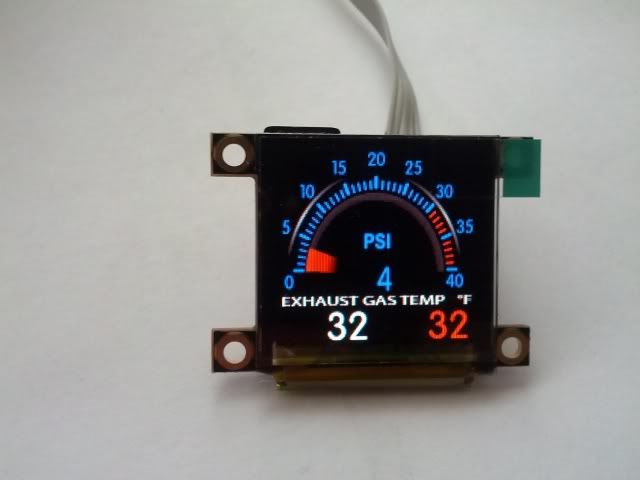
First benchmark was the Doniol gauge. It was low latency, though smoothed RMS values utilized if memory serves, 60 fps update speed digital gauge using an analog sweep. The OLED display was driven on an 8-bit parallel bus by a 16 MHz, MSP430F2410T. It was simple and very fast.
ISSPro
![]()
The even popular ISSPro setup was what my friend had to move to that allowed for daq and gauge use. He had to spend about $600 for the processing board (RS82000) and the gauges (~$170 a piece) combined. He loved the simplicity of the setup because it used 2 wires for connecting all three gauges, though supported up to 17 gauges simultaneously. I'm not sure which protocol was used. In-person viewing and observing other youtube videos shows that the update speed of the gauges was about 5 Hz, aka about 200 ms latency. Due to the stepper motor drivers, the jumpiness is primarily visible on slow movements. I never had a chance to get my hands on his raw data, but due to how it graphed, it looked very much like an 8-bit ADC was used. The signal processor as they called it is fully potted by solid, heavy epoxy and weighed a few pounds.
ZadaTech
![]()
This company tried to ride the wave of the original Doniol gauge. However, they used the out-of-the-box 4D systems OLED displays and drivers. It's a great little device for simple projects and quick graphical development if you don't have a graphics design team. However, by using the 4D board with the graphics ASIC, they only ever achieved about a 10 Hz screen redraw rate. Their attempt at flashy graphics looks a little gimmicky. Oh, and they want 235 GPB, aka ~$390 currently.
Mechanical Gauges
What this video:
Through a little dated, it gives you an idea of the general performance of a digital gauge. From looking at the video, there seems to be some damping going on with the digital gauge that closely resembles an RC time constant. Latency appears to be about an average of 2 frames or ~60-70ms. Especially on a 4-stroke, 4-cylinder diesel, the boost pressure at low RPM can fluctuate 5-10 PSI at 30 Hz or faster. Putting a cheap in-line fuel filter, like the type used on RC cars, provides sufficient damping to the pressure waves to remove the fluctuations on a mechanical gauge and quiets them down.
D-DAQ
There are benefits and drawbacks on each one of these setups. Until it was coded, the Doniol gauge's response was too fast and the RMS + smoothing had to be coded in, much akin to a RC low pass filter or the fuel filter for the mechanical gauge. A mechanical gauge is obviously physical and the inertia of the spring mechanism and the needle's associated sweep speed is something we are used to and don't see, but delays it's response. The smoothing in the Doniol was added to mimic this too. The ZadaTech and ISSPro gauges are prime examples of why I personally have to complete D-DAQ because for their price, their response and performance is utter crap. Though a real gauge face looks better than everything, a physical screen has the lowest response if your data processing and display framework + hardware is fast enough. I've taken notes from all of them, though kept my performance set on being at least that of the Doniol gauge.
If the user wants a full tilt streaming consciousness of D-DAQ's logging capabilities, I'm not sure how much bandwidth I'd need. I've not decided upon a data format, but instead of using floating point everywhere, I'll be implementing an integer math library. A divisor and precision unit will need to be tagged to each data set, but I'll be outputting 16-bit integers, or 32-bit if for some reason I need the precision. At a supplied sample rate of 6.667 kHz, for 14 analog channels, 32-bit integers, we're talking a hair under 3 Mbits. I am planning a 5 MHz software SPI bus for the SD card... Hell, when I have the time, I expect to code D-DAQ to recognize and utilize an Electric Imp for who knows what.
I will also guarantee a screen update speed of 45 fps for the 160x128 OLED screens, though I am aiming for 60 fps if at all possible. Once I know the code execution path, I'll be able to define a latency from the sensor to the display. I'm hoping for this routine to be faster than a single frame, thus 16.667 ms for 60 fps and this seems pretty feasible for a 80 MHz MCU that can do 256 point FFT in less time than that.
Breaking Down Assumed Cost
The mainboard for D-DAQ will come out to about $38 for 3 pieces from OSHPark, who'll I'll continue to use for prototyping. Once everything is working and behaving well, I'll tweak the design to account for the larger annular rings required by SeeedStudio's PCB service to drop the cost further. This board is a touch smaller than the 5 cm x 10 cm proto service. I'm unsure of the specs and cost of the power supply PCB at the time. Since I have more freedom outside of the contest, I plan on making it more robust and 24V compatible.
The gotcha is the BOM. Its still in flux, but due to voltage requirements of capacitors, protection circuitry, oscillators, the physically larger PIC32, et al, we're looking at ~$115-$130 for the cost of parts for a one-off build. It may go up a little more depending on the power supply subsystem changes.
The case of which I'm designing this to fit in is ~$8-$11 un-modified. Once the mainboard PCB layout is finalized, I can annotate the technical drawing PDF and submit it for a quote on the cost of a batch of 50 or so. The case needs to be modified with over a dozen holes about about 6 profiles as well as appropriate mounts for the fan.
The display boards are relatively inexpensive and there are several details awaiting finalization still, but parts, PCBs, and screens for a complete display will cost about $40 without a housing. I live in a city with a low of industry and machining. When the time is appropriate, I'll locate a shop that can provide appropriate technologies for a 2"-2.25" gauge housing and also secure a quote.
Sensor board sizes and BOMs is too much in flux to make an estimate at the time.
That being said, a minimalist setup, build-it-yourself cost for D-DAQ as just a daq is lining up well for the $200 mark. Tack on a gauge, maybe $275. Medium run production would cut that cost
Putting it all Together
So basically, for $200 you can make the base unit yourself. If you want a little gauge, you add on ~$75. Turn than into 3 gauges, it'll be less than $450. Yeah, that price is high. However, you get a 14 channel, 12-bit resolution, 6.667 Ksps data acquisition logger, 3 gauges that can output the data faster than a mechanical gauge, and almost as many inputs as one of the top end systems on the market. Granted, I excluded 2 impulse inputs used for a tach or speedo or to monitor fuel injection. Either way, this will be less cost and easily more than an order of magnitude difference in performance that what's currently out there.
-
Preview of v4
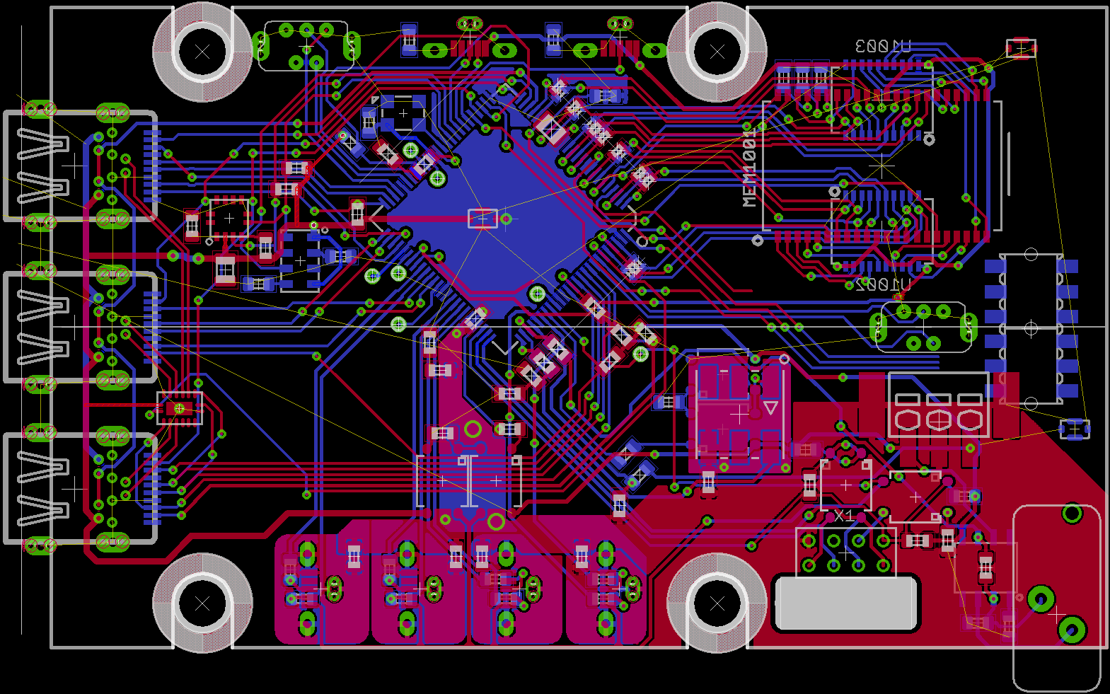
08/25/2014 at 08:10 • 0 commentsHere is where I'm currently at with version 4 of the prototype:
![]()
Thick border is the flat top area on the case. The 4 keepout areas are portioned for grommets for helping shock absorption to the PCB directly. To avoid a large empty mass of PCB, and to position the SD card in a cleaner spot on the other end of the case, the SD card will be on a small-ish daughter board connected via the same pair of right angle interconnects used for the Display Board adapters. The PCB will also help as a guide to allow clean insertion of the card. Mainboard PCB cost from OSHPark is down about $4 too. When I has the time I'll adjust the vias, if I can, so I can accommodate SeeedStudio's PSB fabrication service as they require much larger annular rings.
The to-do list encompasses a few pin points on the board similar to that of the JTAG adapters to connect power to the board, creation of the power supply daughter board (should be a relatively simply copy and paste), ensuring a solid op amp layout for the thermocouple, running the card detect and write protect pins for the SD card, and finalizing the pinout on the 12-pin adapter for the SD card daughter board.
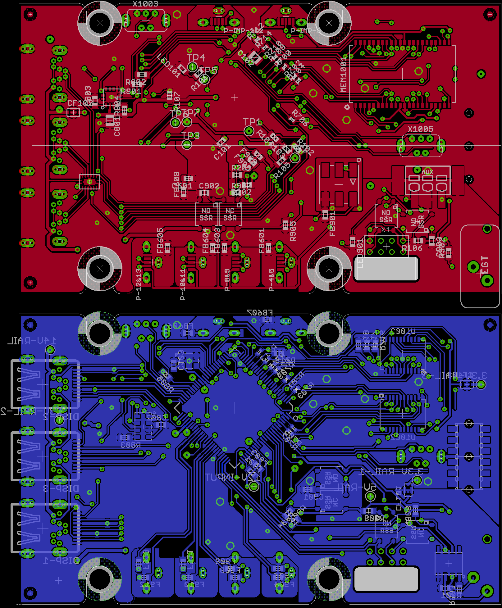
Update
SD card is the only thing left. It'll be a variant of the 8 pin connector used for the uUSB-B slot in the bottom right It is so much cleaner than before. Still have some artwork to add...
![]()
-
The Future of D-DAQ
08/21/2014 at 16:44 • 0 commentsI've mentioned it before, but I just want to state it again for the sake of clarity. Even though I'm a participant of THP and like anyone else I do hope I place, I aim to complete D-DAQ within the deadlines established or as close to them as possible regardless of how I place. I want this device created and design as well as it possibly can be and I'm using the contest as motivation to get it done. Anyhow, good luck to those who are also participants and in the next few days I'll be having the schematic captures for the sensor boards up by sometime tomorrow.
Edit: Well, if you saw my video, you may recall my mention of maintaining TDI's other than my own. First thing this morning I was helping with a flat and a new set of tires as well as some previously overdue maintenance. Needless to say, my day quickly became occupied with anything but D-DAQ. Sorry for not being able to follow through with posting up the sensor board schematic captures.
-
The Case of Cases
08/07/2014 at 23:12 • 0 commentsSee Update Below
Context being more that of the puzzle of cases not one case "to rule them all," but I digress. The past week I've been going through a few catalogs to find an enclosure for D-DAQ's mainboard. Previously, the PCB's form factor was based off of an idealistic & minimal footprint to make it easy to put anywhere and I needed a common IRL item to build from, of which a credit card's dimensions were chosen. Now that the design is maturing, I need to actually put the PCB in something for practical use and that is more irksome than one might think.
So, more than a week ago I began hunting for the "perfect" case/enclosure. I'm a photographer by passion and trade so there has to be an apparent visual aesthetic, though with my obviously technical nature, practicality is equally paramount. I I've seen Dangerous Prototype's case for their boards and recently, thanks to the link roundup post, I became aware of Paul Allen's case for his battery charger. Now an acrylic cover is just sweet and provides enough protection from the accidental touch when you're a hobbyist/enthusiast, but for a potentially hostile environment even as mild as the inside of a car, those won't cut it.
After figuring out the quires to get the right kinds of cases on google, I came across this guy which I was hoping would be perfect:
![]()
It wasn't tan, it'd fit nicely in your hand and supported a PCB really close to my original dimensions. Unfortunately, due to the grips and the pinouts on D-DAQ, this case was just too narrow. I needed like 5 mm more and I'd have been set.
I'd seen the company "Hammond Manufacturing" come up quite a bit, but all I was generally finding was their tan or naturally finished aluminum cases. I was also noting a trend in cases where the access to inside:
- Remove the front or rear panels, which is common for extruded aluminum
- Had one of the two largest faces act as an cap and unscrewed from there, which is common for NEMA cases with gaskets
- Or opened like a clamshell as you see in my first example.
Because I needed a silicone hose to enter the enclosure as well as 9 USB cables, 3 Mini DisplayPort cables, and 3 groups of misc wires, I quickly came to realize that there was no sold way to weather proof this without a major redesign of the the receptacles and significantly enlarging the end device which would inflate the cost as well. So I figured that I had to start thinking in 3D to get this to work and the simplest case design to go with was that with a form factor like my first one up there.
Well, over the past week I came across what was almost my for sure choice, Hammond Mfg's 1553 series in translucent blue.
![]()
With 2 end caps, it was an improvement over the PPL and the translucency, despite my despise of blue LEDs, would do well to allow easy viewing of a few recently added status LEDs on my main PCB. This latter practicality and aesthetic made up for the bulbous design. I wasn't completely satisfied because though it was plenty big enough, I can see from the dimensions of the max PCB that it was too big for D-DAQ.
While trying to trudge through Mouser's catalog for cases, I came across Serpac's A27.
![]()
Heh, if I was going retro, this would be perfect. Nothing against retro, this harkens back to Tron if I added a dash of EL wire along the seams and perimeter of the end caps. For another project, maybe, but definitely not for D-DAQ. I'm sorry. That being said though, this case actually supports mounting 2 PCBs, one in each half of the shell and has a variety of end caps so it's pretty pragmatic.
One last case to show off that I rather liked. When browsing through mouser I came across Bud Industries but due to a friend's recommendation, I had a look at their site. The Style I case isn't half bad looking.
![]()
Unfortunately it's just too square and some of those dimensions are just not listed. Yes, I can reverse engineer them with a little help from Photoshop, but there is another snag. Remember how I mentioned that there are 9 USB cables? I need to get those receptacles to mount as close to flush as I can on the outside of the case. With a style like this, there is a definitive top and bottom side and this adds too much complication to PCB design for me to pull off for the sake of physical form factor.
Well, just a short while ago, I came across another case. Just after the Style I, there was the Style G.
![]()
The picture is a bit boxy, but it has a very similar internal layout like the A27 above. Only difference, it looks a whole lot better imho. The largest suggested PCB is 4.562" by 2.5" (118 mm x 63.5 mm) for the top and 4.562" by 2.875" (118 mm x 73 mm) for the bottom. Since Proto 2, D-DAQ's mainboard was 50 mm x 100 mm. There are 6 mounts for 1/4" self tapping screws on both halves which is more than enough. This is going to be the magic black box where the brain of D-DAQ will be housed.
Now, I wasn't originally going to move over to a separate PCB for the power supply subsystem with revision 4 of D-DAQ, but I know I'm going to have a difficult time fitting that section of the circuit onto the board with the adjusted layout. With a case supporting 2 PCBs, all I have to do is provision for some board-to-board interconnects which will be relatively painless. The added depth and small size of the power supply PCB makes room on that side of the case for a small, internally mounted fan. I'm already going to have to pass to case to a machine shop so what are a few more holes for exhaust vents? All of the USB ports, the EGT receptacle, the Aux. Press receptacle, and the boost pressure sensor will all stick up through the top of the case. The Mini DisplayPort receptacles will actually have to flip over to the bottom of the board for clearances instead of mounting on the same side. Ironically, this makes for a small case of using the original reversed mount receptacles though I'm not actually using the cable for this purpose. Toss in a couple light pipes and the LED indication concern is solve too.
Now that I'm decided as to where this board will be going, I can finalize keep out regions for screw mounts/passthroughs and begin adjusting the layout to take advantage of some breathing room. Here is hoping everything else will fall in place as a result of this decision.
#Update
Still plugging away. Though the case is massively larger than I was wanting, it has room for growth. I'm adding 2 pics to show what I've been doing the past few days. So far I'm figured out some good sized grommets to use for mounting the board to the chassis of the case, created the appropriate parts in Eagle for the grommets, which are modified versions of the holes that SparkFun provides in their library, and have adjusted most routing to stay away from these areas.
Now, because of the huge size of the case for the bottom PCB, see photos below, I will be mounting a largish fan in the bottom of the case, that will be sized under or near 15 mm tall and 55 mm square. I've mapped out and confirmed with the to-scale prints there the end panels lay, the height to the ceiling, wall thickness etc. etc. This work may seem anal or pedantic, but dictates if I have to change parts for the terminal blocks receiving wires for misc sensors, if there'll be enough protrusion or of the USB ports, or if I need a chamfer cut around the holes because a lack thereof.
Tedious work nonetheless and though the results are not physically tangible yet, I just imagine Hannible saying the every popular line: "I love it when a plan comes together."
![]()
![]()
In case you're wondering because you don't recognize it, that's a Voyage 200 in the upper corner. It's large screen, QWERTY keyboard, pretty print equation display, complicated unit conversions, and a CAS make it my go-to calculator. I have a hardware version 1, TI-89 around, but it's it just doesn't hold it own unfortunately against this guy.
-
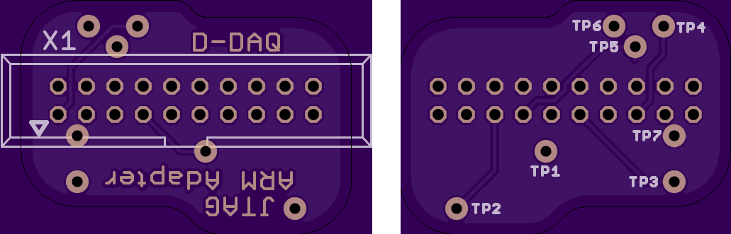
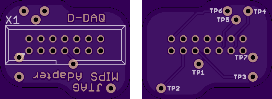
JTAG Adapters
08/02/2014 at 01:24 • 0 commentsHere are 2 JTAG adapters for D-DAQ.
For those with an ARM 20-pin cable
For those with a MIPS 14-pin cable
Since I'm putting neither a 20-pin or 14-pin receptacle on the mainboard, an adapter is required. As long as your JTAG tool speaks PIC32/MIPS 4K, these should work for you. For the pins, I'm using Mill Max's 9976 series pins that have an insertion diameter of 0.018" or 0.46 mm. I've chosen this route to keep the mainboard's layout compact, simple, and to lessen routing complexity.
![]()
![]()
-
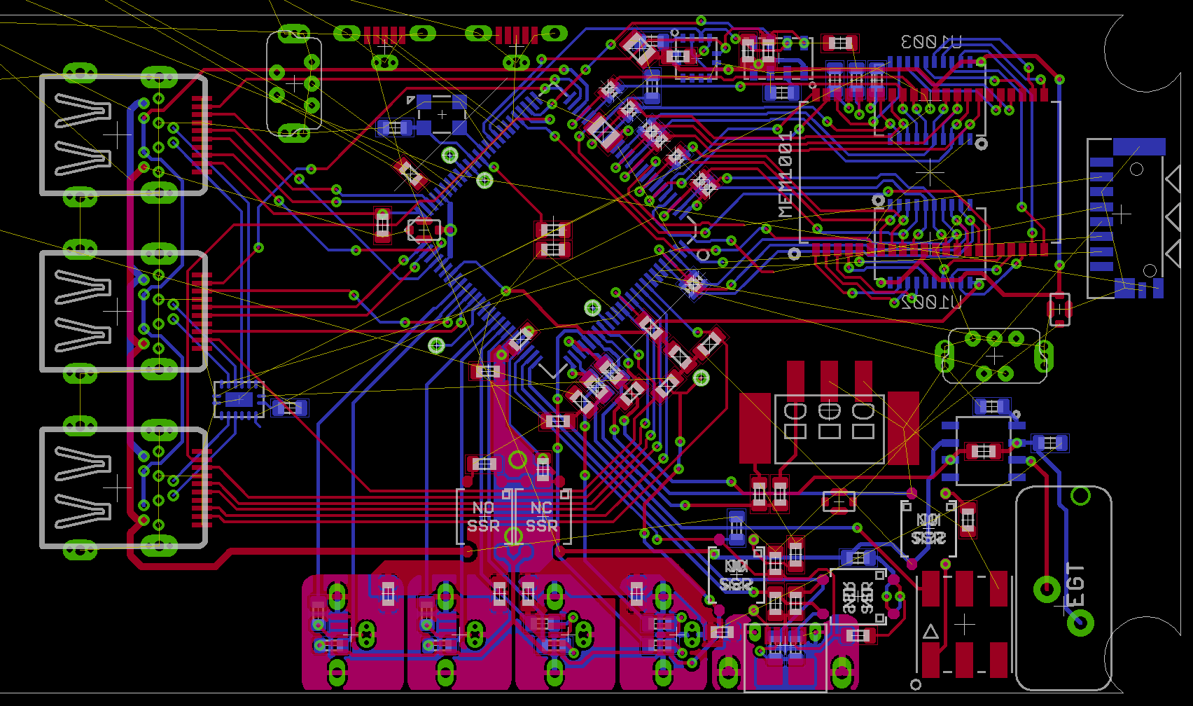
Half way there
08/01/2014 at 11:47 • 0 commentsI'm about 50% done in the amount of time I have left to complete the rest of the board layout. PCB dimensions will be changing a bit, but I'm not sure my how much. I also changed the pinout of the display plugs. It'll take only a few minutes to apply that change to the adapter boards. Screen cap to show where I'm at after the break.
![]()
Still need to figure out a few things and tweak stuff. The power subsystem will "simply" be copied and pasted from what I had before and then routed into place. However, I may be changing the SMPS controller IC to less electrically efficient but more thermally efficient part since I'd need power current if there is a uC on the other end of each display cable. After that, if I have room to trim any fat, I'll squeeze things together.
If you've followed closely, you'll note that there is no 5x1 pin header array. I moved to localized pin receptacles instead. Since there is no standard 5-pin JTAG/EJTAG layout, I have to make an adapter from the common ARM 20-pin layout. Since it requires another board to be placed in between the cable and the DUT, I figured I'd combine the two in a manner that eased routing on the mainboard. It'll take all of 20 min to copy the pin locations onto a new board and route it.
-
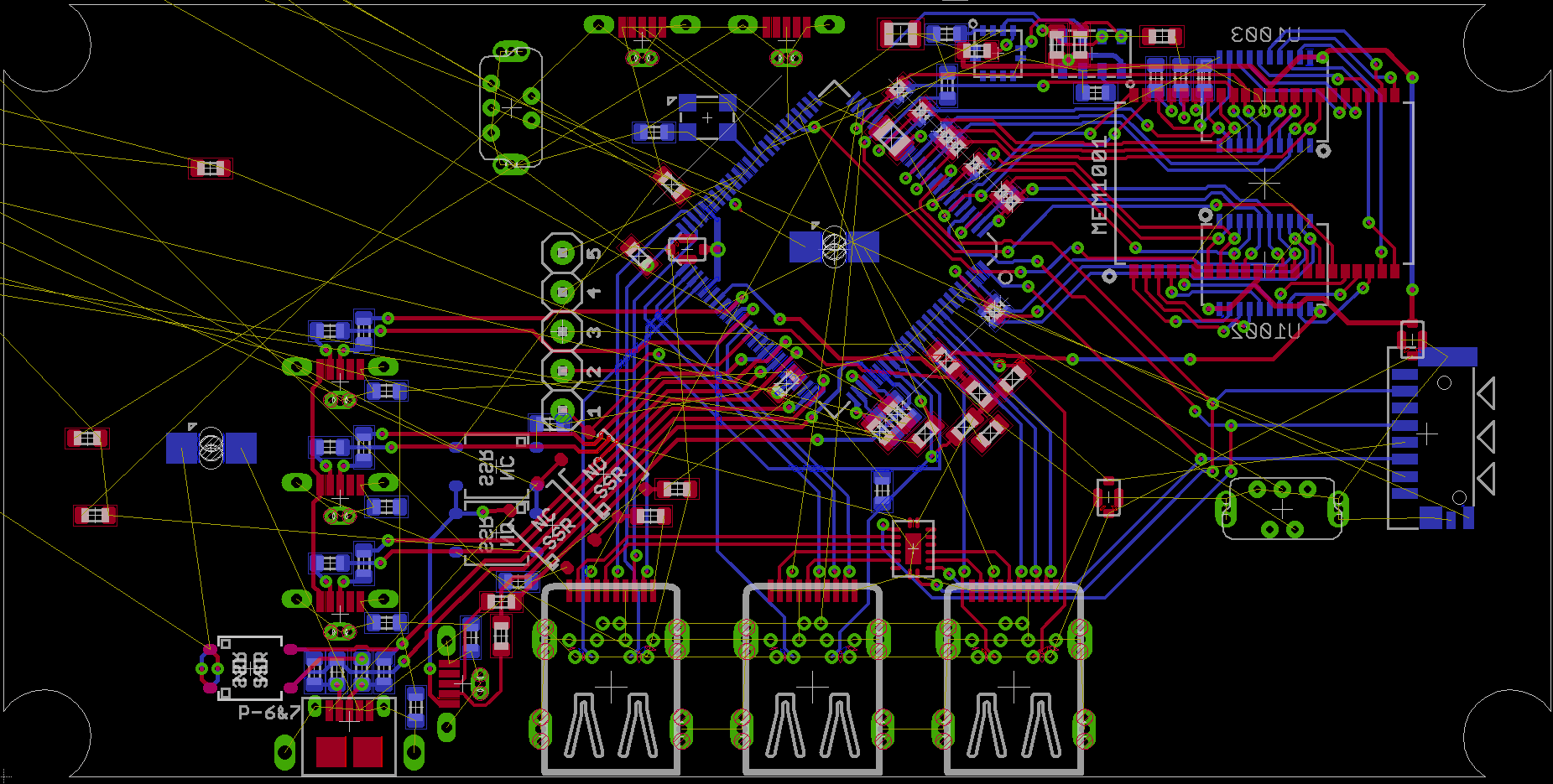
Still working...
07/27/2014 at 04:43 • 0 commentsOnly 4 days since I've posted a log? Being on vacation messes with your sense of time if you stay home... Anyhow, I've been working on board layout for about a day and a half and I'm about half way done with the easy stuff, I think.
![]()
If you open the pic up to a larger form You'll see what I'll be doing next. Now, this layout is similar to that of my previous iterations, though I didn't realize how much difficulty I was forcing myself to go through to maintain this form factor.
Right now I have the traces for 2 displays going under the analog inputs. That is also about half of the routing for the displays too. For simplicities sake I'm going to swap the nomenclature of the displays; this alone is overcoming personal stubbornness and a little OCD. Basically what it'll end up looking like is just having the displays rotated to CW to the left edge and the analog inputs rotated CCW to the bottom edge. The JTAG header will probably move down further from what I can see though.
Either way, the routing for the software SPI will be a tad difficult, but that's 3 lines instead of 12. Display 1 will become 3, 2 will be 1, and 3 will be 2. Memory layout with forced serial termination, which may not be needed for speed though should help with noise suppression, was a lot simpler and I didn't bother trace length matching. I can go on over the changes, but I'm back to work tomorrow and there are few changes from the last update I posted.
Schematic capture will be up on github soon though I'm not recording sub-versioning due to changes or what not that come up with the layout. Once I finish this layout, I'll post more details.
Last tid bit. I don't have code running, but due to problems encountered with existing hardware, it wouldn't matter much. The last board fabricated was of version 3 and I was at ~v3.6 internally due to problems found. I'm now on version for and that last log pointed out numerous issues. R&D is expensive...