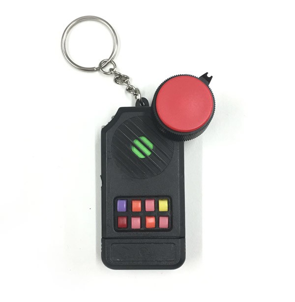
Remember those 80s keychains with the laser noises? Some were called the Executor, The Echo Keyller, Thriller, and some other names. This was my first real circuit bending project (that's why I called it Patient Alpha) and might be of interest to those looking to circuit bend this thing or something like it.
These are the steps I took to replace the resistor in the RC circuit with a pot, then added a headphone out jack. This thing really screams.
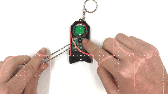
So if you're working with a battery powered device, you can find tweakable parts on a board by rubbing it with a licked finger (this might be obvious to some, but I had no idea :)
You don't want to do this with a device plugged into a wall. This is a quick before/after video:
This board is super simple, and the only thing that made it squak was the resistor on the top right as I triggered the button pads with the tweezers (pin to ground). It's labeled 224, and for those really starting out, that means 22 times 10 to the power of 4 = 220,000 or 220 kilo ohms.
So I thought why not replace it with a variable resistor (potentiometer).
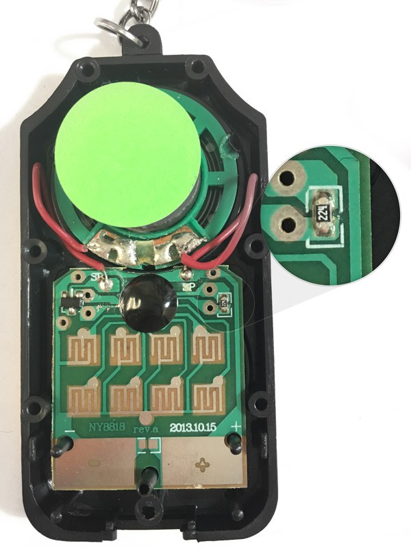
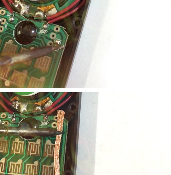
First remove the original resistor by heating it up and using some solder wick to absorb the remaining solder.
It's kind of amazingly convenient that there are extra pads right next to the pot and on the power traces on this 2013 reissue of the keychain. The original 1989 version had no such thing:
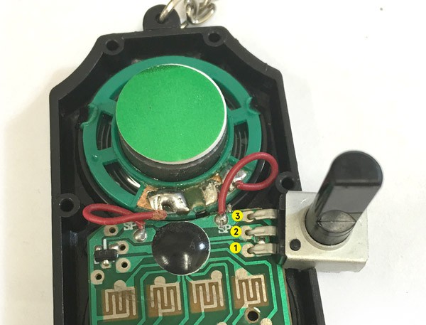
I labeled the pads so it's easier to talk about. Here's the funny part, using the 100k pot on 1 and 2 (which are the original resistor pads) acts in a way you might expect. Approaching 0 resistance the sound gets faster and faster (at 0, it zappy/and shorts, which is not good). As you turn to 100k it slows down. But at 100k it's still about twice as fast as 220k, which makes sense. So 1 and 2 are kind of "fast" to "superfast"/zappy.
So here's the weird part, and where my knowledge starts to suffer, plugging the third pin of the same pot into pad 3 (which is power), widens the range a LOT! At the higher resistances, there's even a really slow spot (think slow motion). And there is a lot of dead space at the bottom. Which might just be because the whole circuit is getting shorted, and it'll just drain the battery (not sure, open to comments). But this 1,2,3 combo works if you want to give it a shot. 1 and 2 I call the "Easy Peasy" mod and it's just fine, but the range could be wider, and the zero short can be a problem (like if you leave it at zero, your battery will just die).
-------------------------------
Cutting the Enclosure
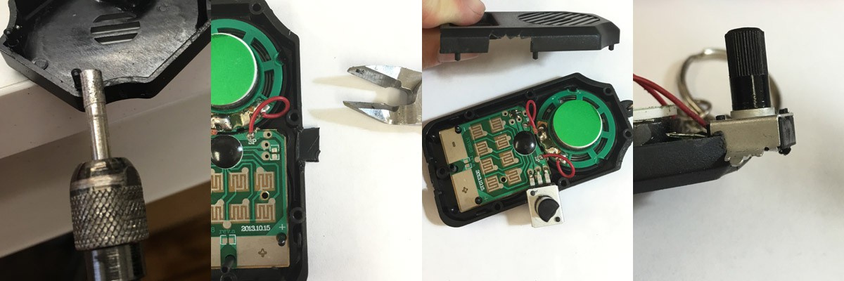
A quick interlude about actually getting the pot in the case. I think the top right shoulder of the enclosure is a pretty good spot (press buttons with your left hand, twist knob with right hand), but it could go anywhere really. You can dremel it, which was my favorite at first, you can hotknife it (which takes its own kind of finesse, have to be smooth and fast and precise), or you can just snip it little by little with some snippers, which honestly became my favorite because it's the most peaceful.
You just have to not get too ambitious at once and take little bites in a sawtooth fashion. If you go for too much at once, you risk cracking the case, which isn't too big a deal because you can glue it together, and the area around the pot will be covered up if you use a sizeable knob (which is the most fun).
----------------------------------------------
The Right Amount of Resistance
The best experience in my opinion is when there's a wide range of speed and no dead zones. So here's the combo that works for me every time (but I'm sure there's a ton more things that could happen). I raised the ground with a 10k and a 10 ohm...
Read more » Nickolas Peter


 Anthony
 T. B. Trzepacz
 SukkoPera
 Brett
Brett
This is probably an oscillator with some kind of schmitt trigger gate. The strange behavior is due to use of the supply voltage. I would have used a series resistor of 10k to 22k and a pot of 500k to 1Meg. Both connected instead of the original resistor. Then you would have a nice range of variation from 10 times the speed to 1/2 or 1/4.