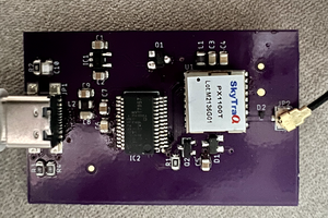
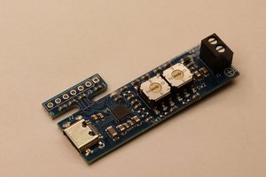
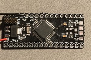
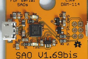
This project, in principle, is quite simple - it's two chips - a Cypress Semi CY7C65213-32LTXI and a Texas Instruments MAX3243ECRHBR. The former is a USB UART. It's pin compatible with the FTDI FT232R's QFN variant, but instead of a proprietary driver, it implements the modem class, so generic drivers provided by the OS will match it. It supports a TX and RX LED, and will be connected up to a micro-USB connector. The other chip is a 3-out/5-in RS-232 level shifter. It requires 4 capacitors to run a charge pump to generate the bipolar supply required for RS-232 signaling, but other than that (and a bypass cap), it requires nothing else.
There are two control inputs on the MAX chip - FORCEON and !FORCEOFF. The chip has some relatively sophisticated activity detection circuitry to automatically shut the chip down when invalid levels are present on the RS-232 side. While that's a nice idea in principle, we don't necessarily want to enforce connecting all of the signal lines up. So FORCEON will be pulled high. !FORCEOFF is intended to be a shutdown signal. The CY7C has a !POWER output pin which is asserted only once the device has been properly enumerated. In keeping with best practices for USB devices, we'll connect !POWER to !FORCEOFF so that the level converter is powered up only when the UART is. The MAX chip has one receive channel that has an alternate output that is always enabled. But since FORCEON is held high, it's moot, so it will be left disconnected.
That's all there is to the project electrically, but I wanted to make this into something small that could be used semi-permanently to adapt RS-232 peripherals to USB. So the intent is to design a housing that looks like a molded DB9 shell, but instead of a cable coming out of the back, it simply presents the micro-USB socket.
At the moment, the board is 1.3x0.6 inches, which won't quite fit in cable housings as they're presently designed. The hope is to be able to design a custom enclosure that has the same dimensions on the DB9 end, but tapers down to an acceptable shape ending in the USB port. Additionally, a couple of holes that can be used to install light pipes to bring the RX and TX LED indications to the surface of the case would be nice. I have zero 3D modeling skills, so that's going to be the challenging part of this project.
There's a second variant of the board that simply leaves off the RS-232 level conversion chip. That variant has a 6 pin SIP header with the standard Arduino "FTDI" pinout. You can solder a male SIP header onto it and plug it right into a breadboard, or a right-angle female SIP header and plug it into some other device with the mating header. Since this variant passes Vcc out to the target device, a couple of protective measures should be taken to protect the host and insure that the device remains within the USB specifications concerning current draw. A USB device isn't permitted to draw significant current until the host completely enumerates it, which gives the host a chance to figure out that the device would draw more current than is available. The !POWER pin noted above can be used to signal that. In our case, we can tie it to a P channel MOSFET to allow us to turn output power on and off. In addition, we can put in a solder jumper to allow us to output either 3.3 volts or 5 volts (to make 3.3v, we need to add a small LDO). We can tie the selected voltage to the CY7C65213's VCCIO pin so that the signaling is the correct voltage as well. Lastly, we will use an AP2331 current limiting switch on the output to protect the host from inrush.
 Nick Sayer


 MagicWolfi

Hello Nick,
I recently found your project and bought 2 of the ftdi-be-gone, they work perfectly and the lights for rx and tx are really helpful.
I would like to suggest a small change to the design, I would like to see like a clone of the same project but with an RJ45 termination on it, instead of the rs232 plug.
So.. same electronics inside for the rs232 signal but with a rj45 female plug, I bet many people will appreciate the value of having the same electronics but in a smaller package, and your change on the board will be nothing.
Below are some photos with the adapter I use for this.
https://imgur.com/gallery/VTVb8f6
Thanks for your time.