Vladimir Savchenko
-
Project completed!
06/03/2016 at 12:46 • 0 commentsI have decided to complete this project portal, as i opened a new one that is based on the final device
https://hackaday.io/project/12063-vesprino
I am happy that in fact i have overachieved (in my opinon only of course :)) ) my initial goal
- The cost of the device is kept as low as possible
- I managed to streamline the extension ports and now they are all on one side of the board, making it extemely bread-board friendly. And also having them as female headers on the edge of the box, makes it very simple to really extend the device with additional sensors
I really would like to productize this device so i am going to start a crowdfunding campaign as it needs to scale so that production costs can be.
For anybody interested i've created a subcription list, where i would send notifications once the campaign is started (hopefully)
-
Enclosure Designed & Printed
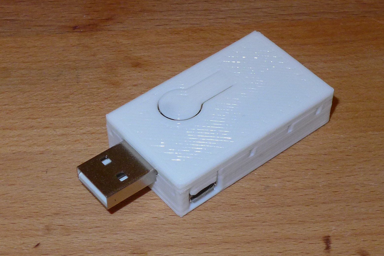
05/31/2016 at 03:24 • 2 commentsAfter a few trials i managed to create a nice box for the device. Something i really hate and kind of frustrates me is having some breadboard with jumper wires, then some usb cable for connection to the pc and everything tangling up on my desk.
This small box prints for about 15 min on my Felix 3.0 Printer, has a built in button plane, hole for the micro usb port.
![]()
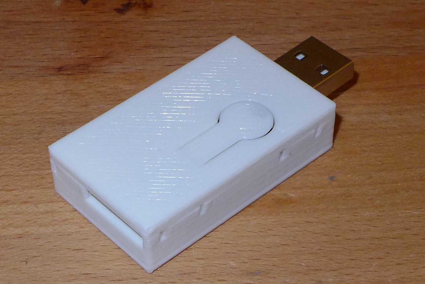
And another hole on the opposite side for the pin header for additional connections. Maybe this will change as it turns out 90 degree female headers are quite hard to find and expensive, so another option is to make the hole on the top/ Which would make the box ~ cm smaller
![]()
I also tried creating a video, but it is hard with the low dynamic range of my camera
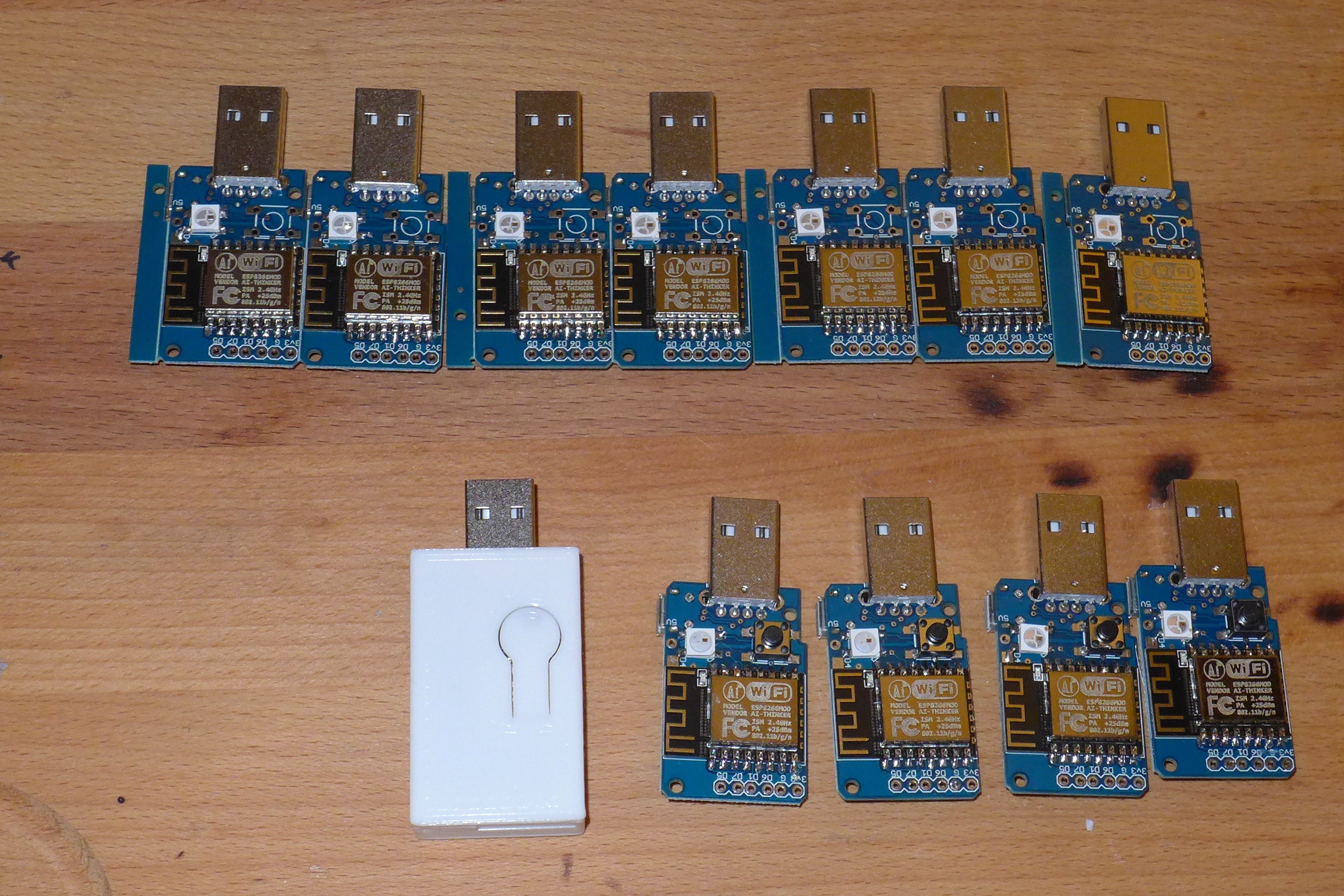
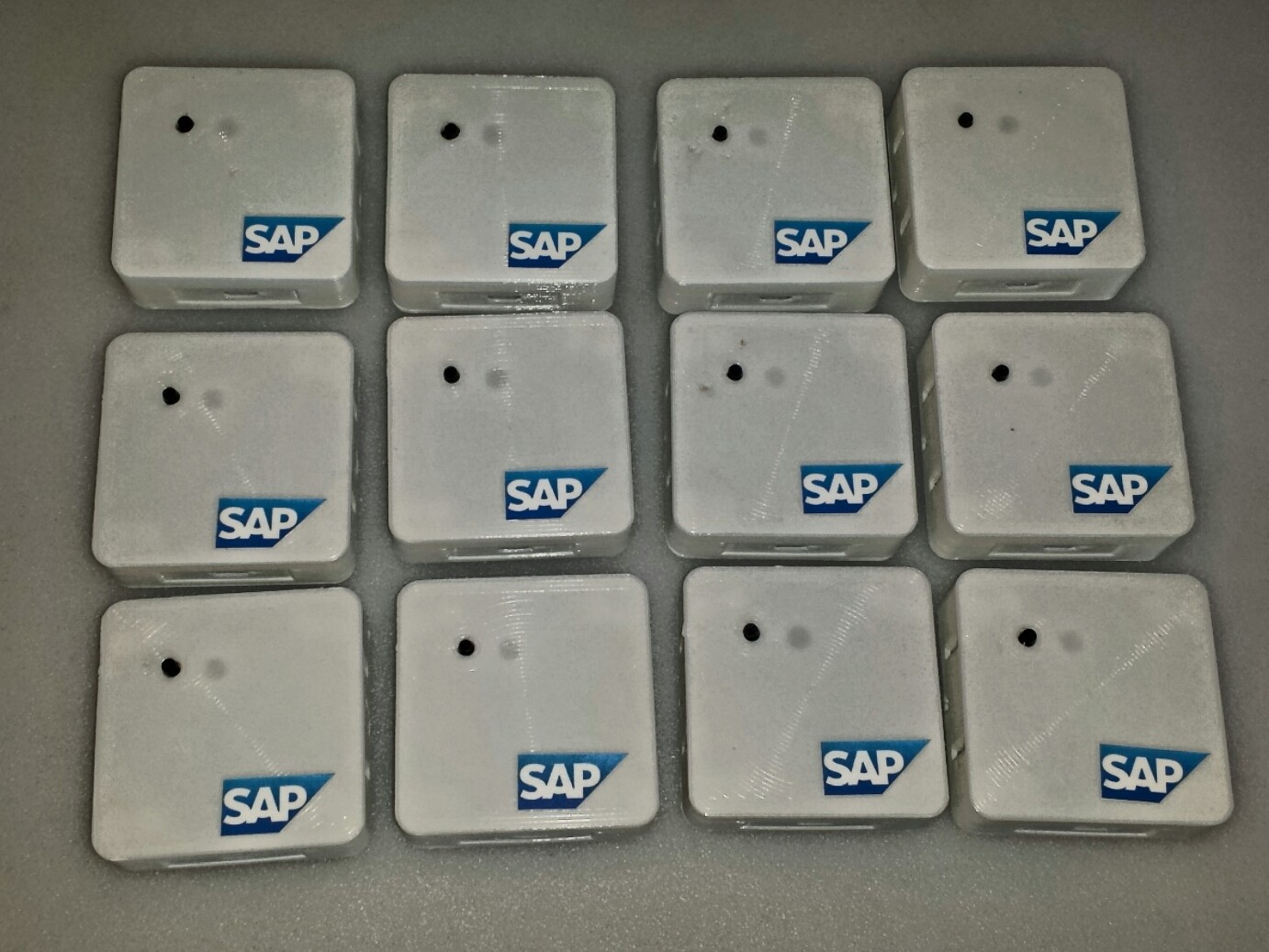
I even soldered a small batch, to use on my next training event coming up in a couple of weeks. Now i need to print some boxes and design some nice stickers for the top
![]()
-
3rd Version arrived and Working!
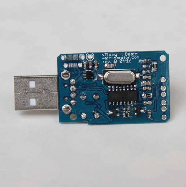
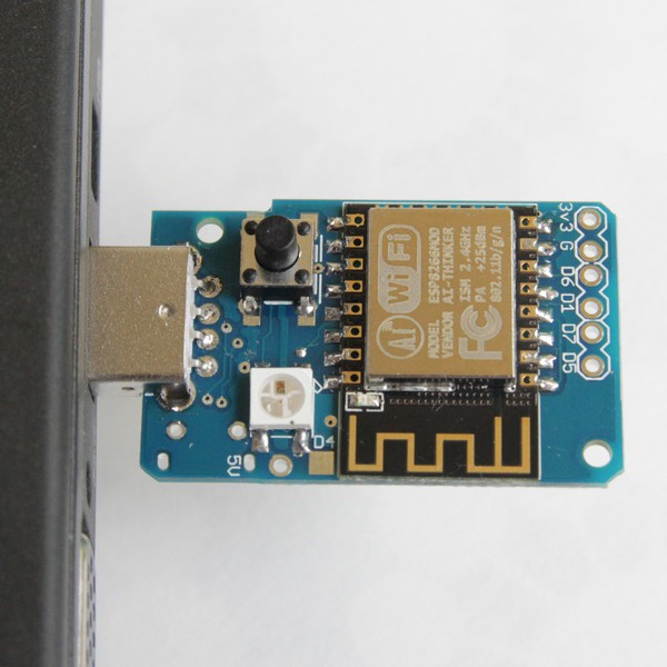
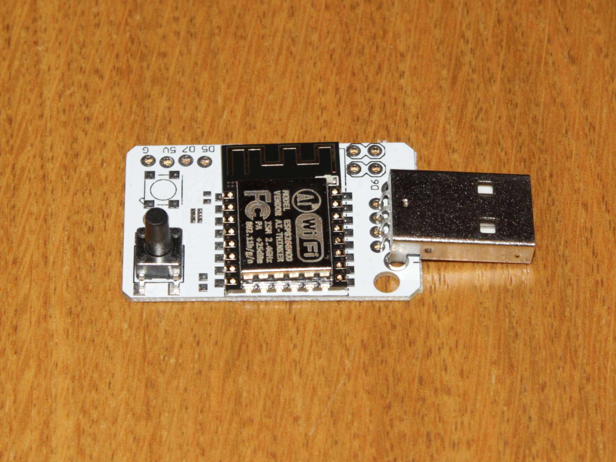
05/05/2016 at 17:24 • 0 commentsI am very pleased that the 3rd revision of the boards has arrived. Upon soldering it it turned out that (almost) everything is fine. So there will be perhaps a 4th revision, but this depends on how the project will move forward.
The next step is to create a basic enclosure and print it on my 3d printer.
But so far it looks pretty sleek
![]()
![]()
-
Waiting for 3rd board version
04/15/2016 at 19:54 • 0 commentsUnfortunately it turned out that there were some unrecoverable problems with the 2nd revision of the board (and i had ordered 200 of them :( ). So now i fixed them and now i am waiting for the next 200 (ahahha). This time i switched to bigger components so that i can at least have a chance to solder them myself to get faster some result.
-
Boards have arrived
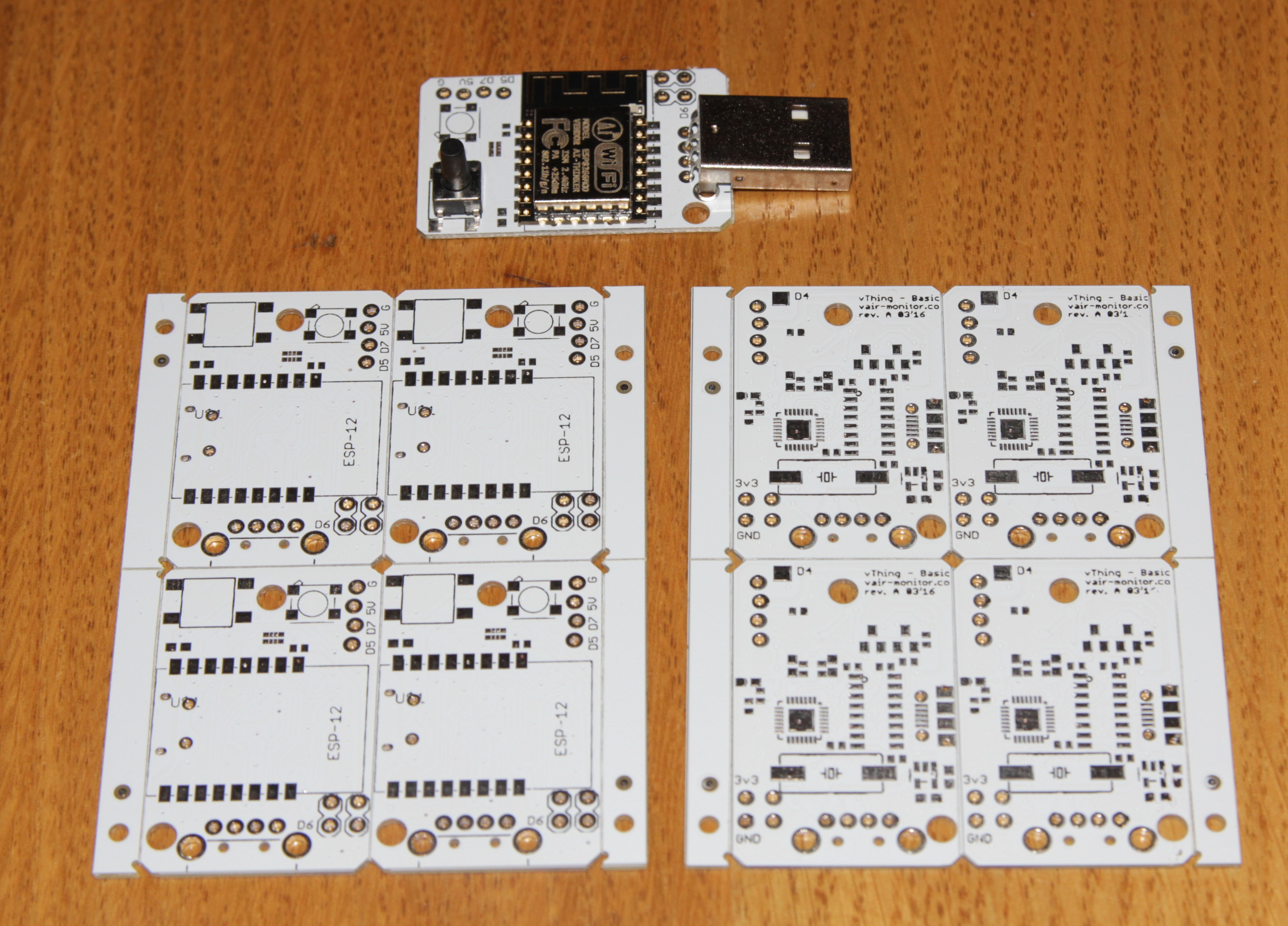
03/23/2016 at 04:32 • 0 commentsFirst batch of boards has arrived!
As expected - there are few issues that would complicate the assembly a bit. But hopefully there will be no functional issues once they are assembled.
Here is how big the device is really going to be:
![]()
and a photo of the first revision of the board panels:
![]()
I hope the assembly factory will manage to assemble them in a week and it will work :)
-
Ordered 2nd revision PCB
03/14/2016 at 14:13 • 0 comments![]()
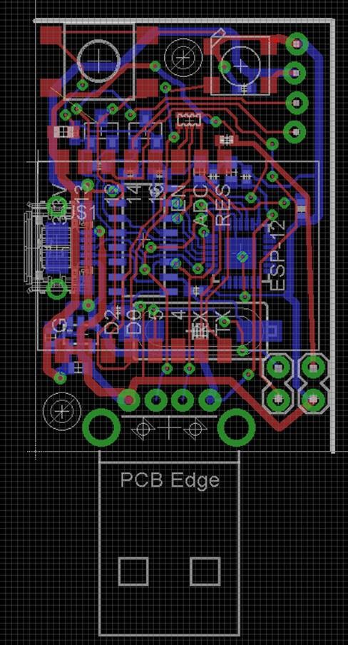
I was quite busy in the last weeks - preparing the first batch of devices for the event. While doing this it turned out that i had done some mistakes in the initial PCB design of the prototype, which made the soldering very error prone (also the fact that soldering by hand was required). This is why i designed a second revision of the PCB.
The new design is much closer to what is on the picture of the project. The main difference is that there is only 1 button and the size is 40mm length x 25 mm width.
On the other hand i did few changes to make it a bit more portable:
- Added a Micro USB port on the side
- Added 2 mounting holes
- Added one port with 2 GPIO, GND and 3.3 V
- Added second port with 2 GPIO, GND and 5 V
- Added a pad to the WS 2812B led, so that if desired - more LEDs can be attached
The goal of those modifications is to allow the board to be a bit more reusable and embeddable into devices that do slightly more. E.g. I2C, Serial communication, LED Gauge indication, etc.
I am not entirely sure that there isn't again some small mistake in this design as it will cost ~$ 150 to fix it :) But in any case i ordered 200 boards.
-
First Version Tested
03/14/2016 at 13:59 • 0 commentsI had a chance to test the viability of the project on a recent event. For this i produced 20 devices. Since i used an existing main board - they were a bit bigger than expected, but anyways it was nice to evaluate it. This is how the devices look like. There is a button and an RGB LED. The simple scenario I used was to let the participants connect the device to a HANA Clout Platform IOT Service and make use of the Button to trigger events, the LED to be controlled via a Web Application, and report the temperature online.
![]()
![]()
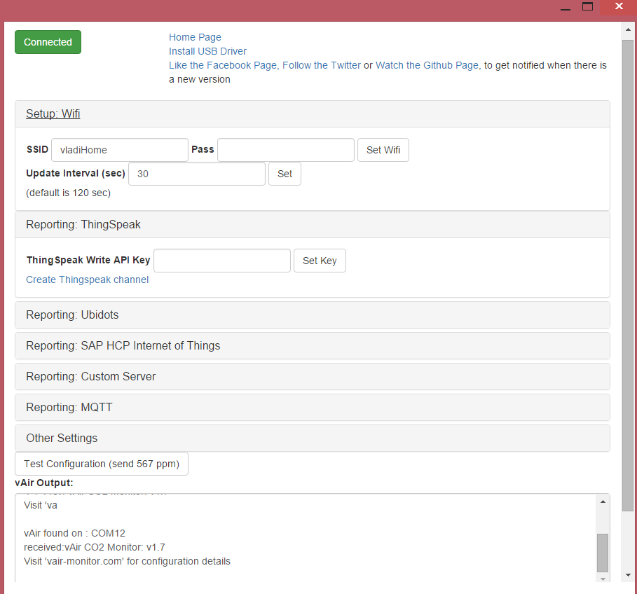
It is all configured by connecting the device via USB to a computer and then using a Chrome Application to setup all necessary stuff.
![]()
Next step for me is to build more examples also using other platforms like Thingspeak, Beebotte, Ubidots, etc.
-
Update on target price
02/15/2016 at 07:41 • 0 commentsAfter getting some specific quotes for PCB Fabrication and assembly, it turned out that the target price can be decreased even more.
PCB price will be something like 0.3-0.15$ (200 - 1000 units).
So if we take 500 units, than the pcb fabrication and stencil should be ~0.25$. Instead of the ~1$ that i initially planned.
vThing Starter
Lower the entry bar to IOT Development as much as possible