I hadn't looked at this project in awhile, and discovered that way back when I'd ordered some inverters and XOR gates! Free parts, just sitting there.
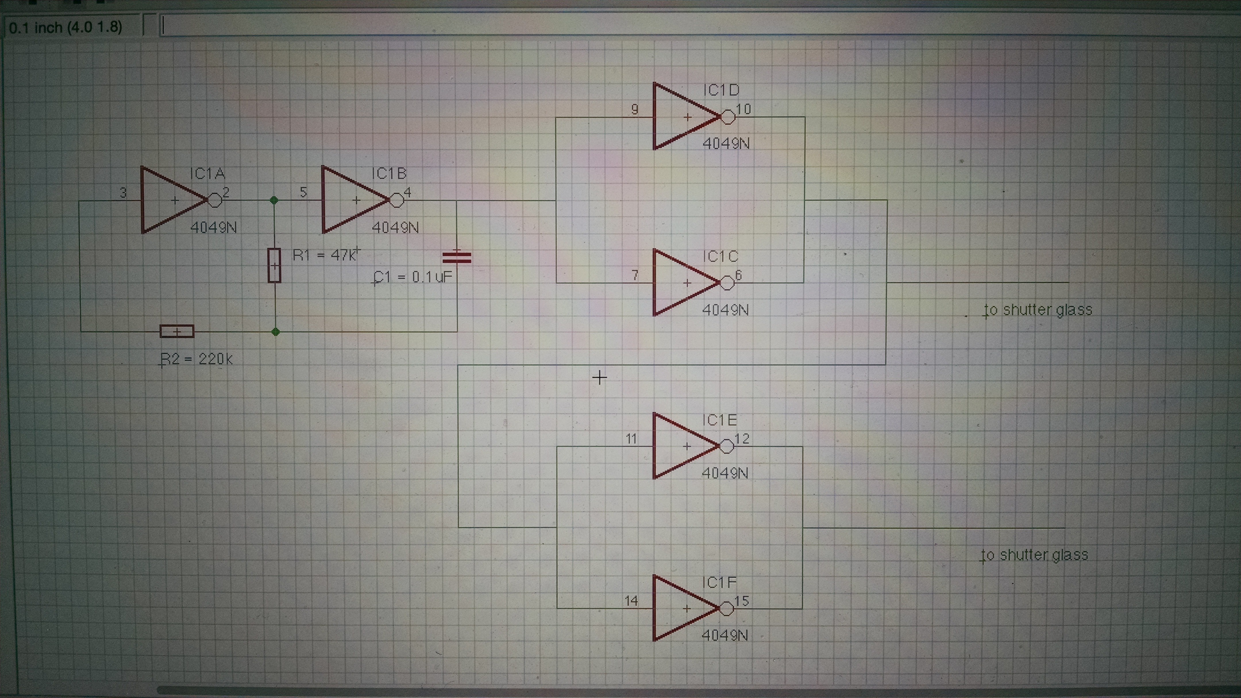
So I built a quick circuit with one of the hex inverters (CD4049) to drive the glass:

The formula for frequency is determined by R1 and C1 is F = 1 / (1.39xRxC) ... I tried with a 47k resistor and a 330k. In both cases, the glass appears dark.
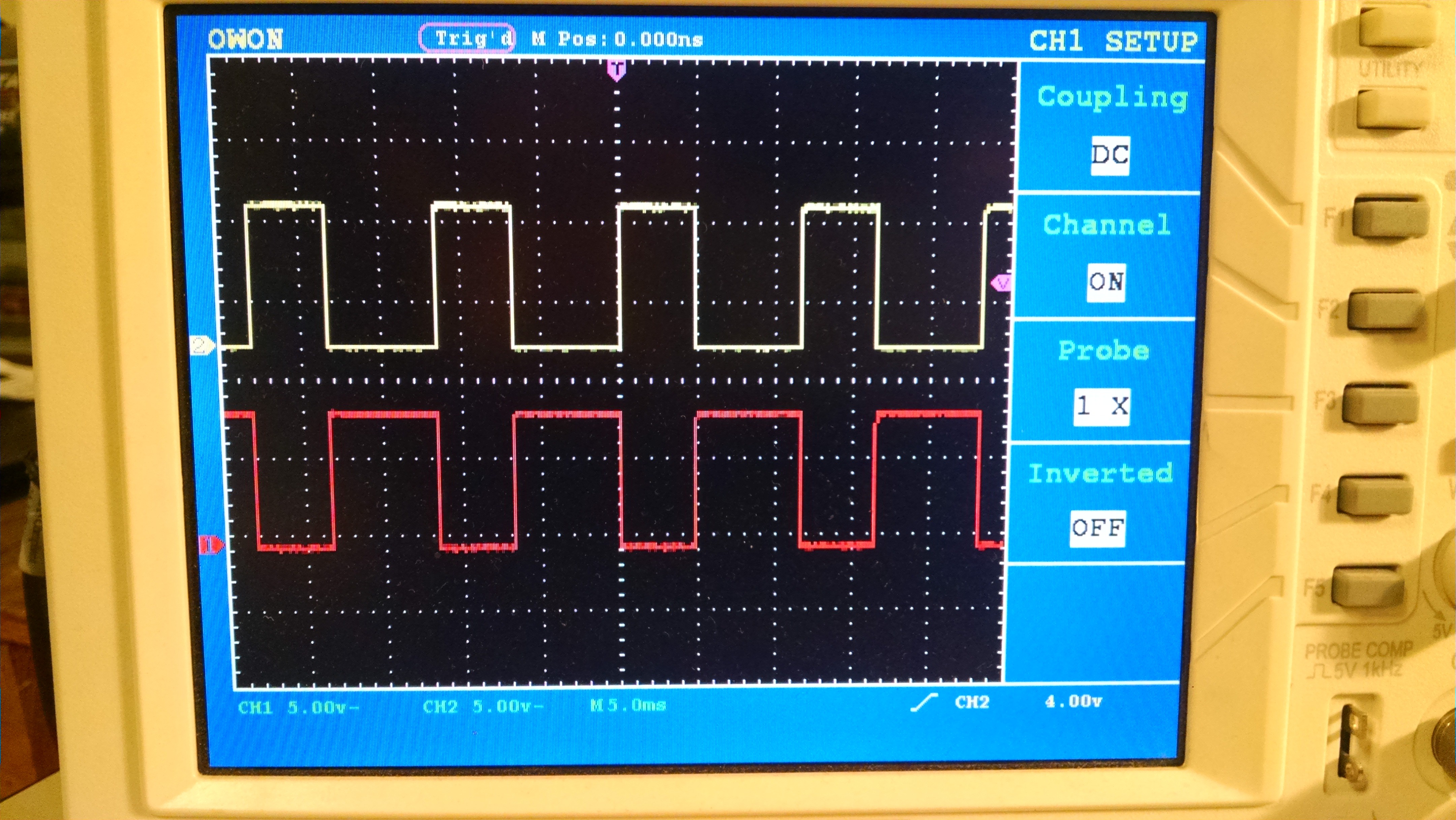
What I want though, is for the glass to be able to dim. The correct driving wave form should look like this, but in order to vary the brightness/ dimming, needs a PWM signal.

 Sophi Kravitz
Discussions
Become a Hackaday.io Member
Create an account to leave a comment. Already have an account? Log In.
You can dim them by playing with the supply voltage for the 4049. It is low power, so you can probably get away with a trimpot in series of the 4049 power supply pin. Make sure to put the decoupling cap on the chip side.
Are you sure? yes | no
Hi @K.C. Lee! Good call, I just tried that and it works.
Are you sure? yes | no
Hi Ted! You're right. See the pic of the correct waveform I just posted. This is with 47k at R1. However, this won't dim. (reading your comment). Yes, true, you need to drive them with an AC PWM signal!
The circuit I've got here doesn't allow for PWM, hopefully the next one will.
Are you sure? yes | no
Interesting about the driving voltage dimming them - there may be a temperature dependence involved.
BTW, may I ask where you obtained the shutters, and if you have specs for them? I bought some wired 3D glasses a few years ago to extract the shutters for possible use as photographic shutters, but found they were too slow for my purposes. I suspect any LCD is probably a little slow for a fast camera shutter, but maybe there's one out there somewhere...
Are you sure? yes | no
Hi Ted! I get the shutters from Liquid Crystal Technologies in Ohio. I've been buying sample sizes from a die cut that they've got extras of. http://www.liquidcrystaltechnologies.com/
Still, even as samples, they're pricey at $25 each for 1" x 2" piece. In quantities of 400, they'll come down to $10 each. They're TN shutters and optimal voltage is 3-15V and operating temperatures: 0C to +50C. storage: -10C to +60C.
And for $2000 you can get your own die cut shape which is pretty cool and a direction I'd like to go in at some point.
You can also hack welding googles to get the shutters out of them. I never looked into finding shutters at welding google manufacturer, but that would probably be a good and cheaper place to look.
Are you sure? yes | no
Thanks, Sophi! I have an auto-darkening welding helmet, but since it was one of those safety items I didn't go cheap with, I've always had it in the "don't hack" mental pile. Maybe I'll look around for cheap or broken ones to test.
Are you sure? yes | no
You would have to increase the voltage at low temperatures by using thermistor circuit.
http://www.hantronix.com/files/down/tempcomp.pdf
Are you sure? yes | no
( also @K.C. Lee ) maybe if you can fit an LED/phototransistor pair in one of the corners, you can measure the transmission. An op amp and feedback loop could regulate the shutter voltage and keep the darkness right where you want it, independent of temperature.
Are you sure? yes | no
Now you are assuming that the LED/optotransistor efficiency has no temperature dependency. :P
http://www.digikey.com/en/articles/techzone/2011/oct/identifying-the-causes-of-led-efficiency-droop
See 2nd graph with family of curves over temperature.
Are you sure? yes | no
@K.C. Lee Yes, true. You could use a second LED/phototransistor pair with a clear aperture between them as a reference to compensate, like compensating a diode or transistor in a log converter.
Then, there's matching to consider of course...
Are you sure? yes | no
I haven't read the docs you posted, and I'm certainly no expert, but it was my understanding from previous projects that you had to drive LCDs with a completely symmetrical square waveform to prevent any DC polarization that will eventually destroy them. To dim them, I think you have to drive them with a square wave for a fraction of the total time - square wave for a few cycles, then no drive at all, then square wave of a few cycles, etc, in a PWM manner. During the "off" (clear) period, you don't want them energized either way - you want them basically disconnected from the circuit, like with a tri-state output.
EDIT - like figure 2 of this reference you posted:
https://cdn.hackaday.io/files/9676413977984/Driving%20TN%20Shutters%20(Rev%203).pdf
you can use the control input for PWM dimming of the shutter, although ideally the PWM signal would be synchronized with the clock to keep an even number of square waves applied to avoid DC biases on the LCD.
Are you sure? yes | no