 Annelle Rigsby
Holes in the board book that are misaligned or not clean can impact the output of the photo resistor. To verify the voltage received on the analog input pins of the Arduino, I attached wire wrap wire to the resistor junction that connects to the analog input pins. I labeled the wires (1 through 5) as shown below.
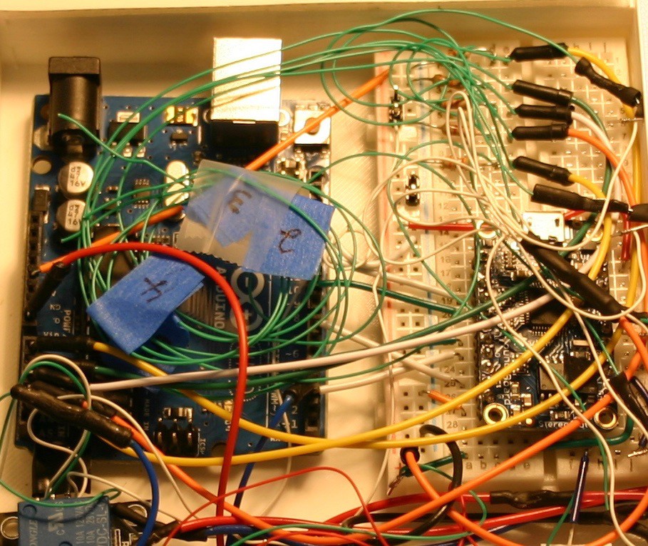
I brought these wires out (as well as a ground connection) and placed the board book on the electronic housing. In normal room lighting, I opened the book to each page and recorded the voltage on each input pin. The "dark" readings were about two volts (light leaks in from many places). The "page open" readings were 3.5 volts or higher. Pages deeper in (less hole space for light to travel through) read a little higher. If the room was lighter, the readings were higher.
Because zero to five volts on the Arduino results in readings of 0 to 1023, the open readings would correspond to a value of about 700. I didn't want to cut it too close, so I used 600 as the number to indicate a page was receiving light.
Discussions
Become a Hackaday.io Member
Create an account to leave a comment. Already have an account? Log In.