 Annelle Rigsby
Here's what it works like:
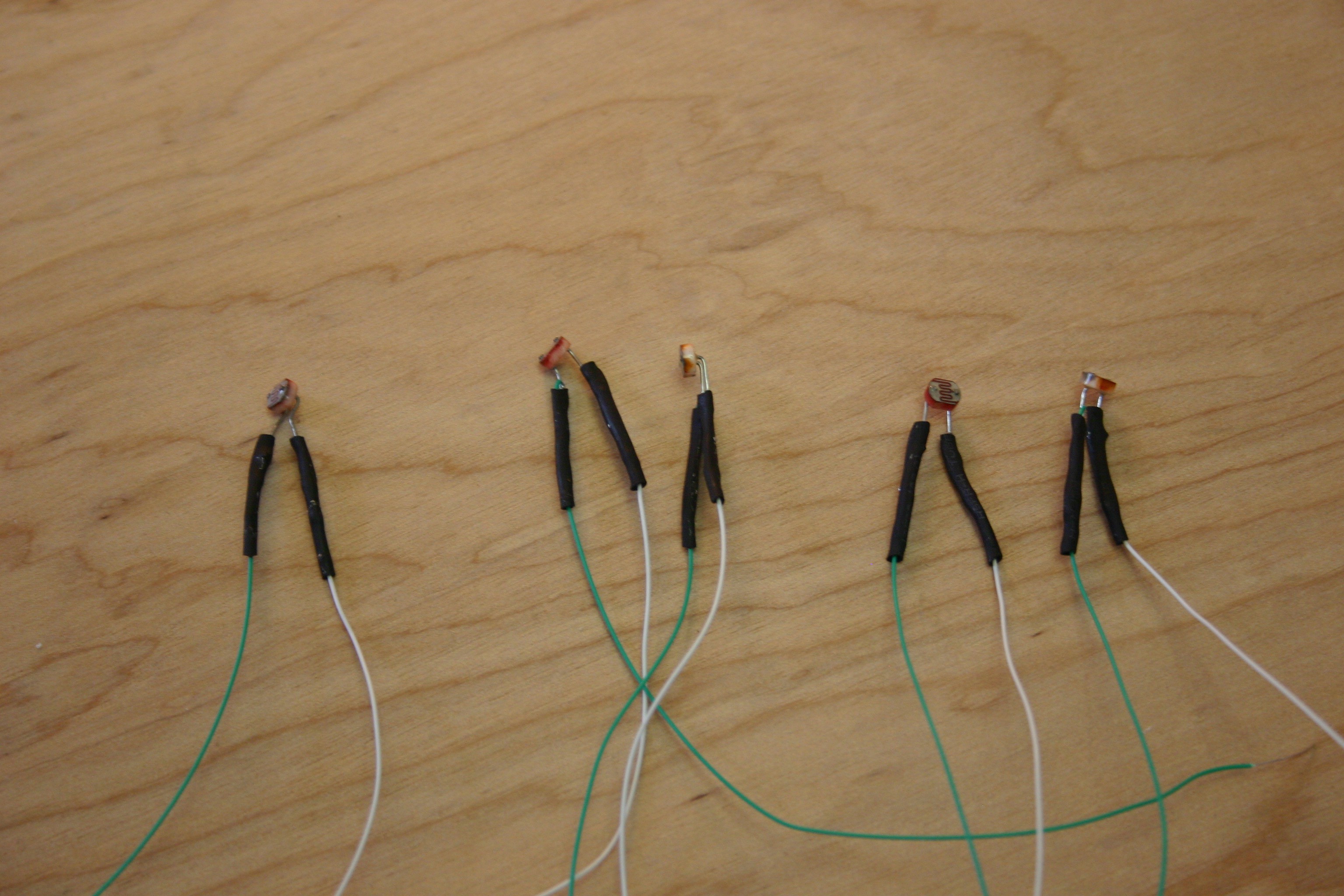
I started by soldering wire wrap wire to the photo resistors, then shrink wrapping the ends to prevent shorting.
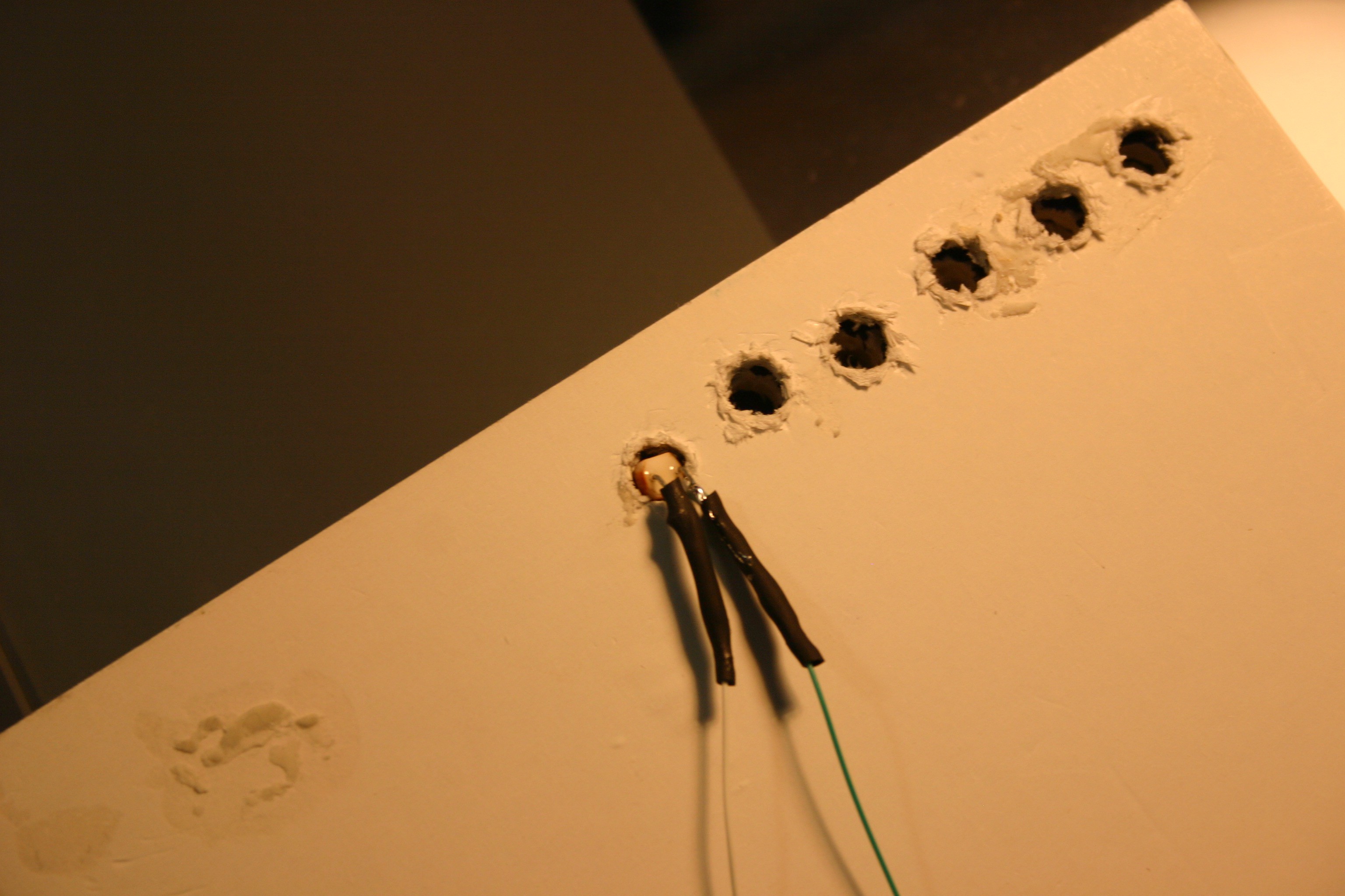
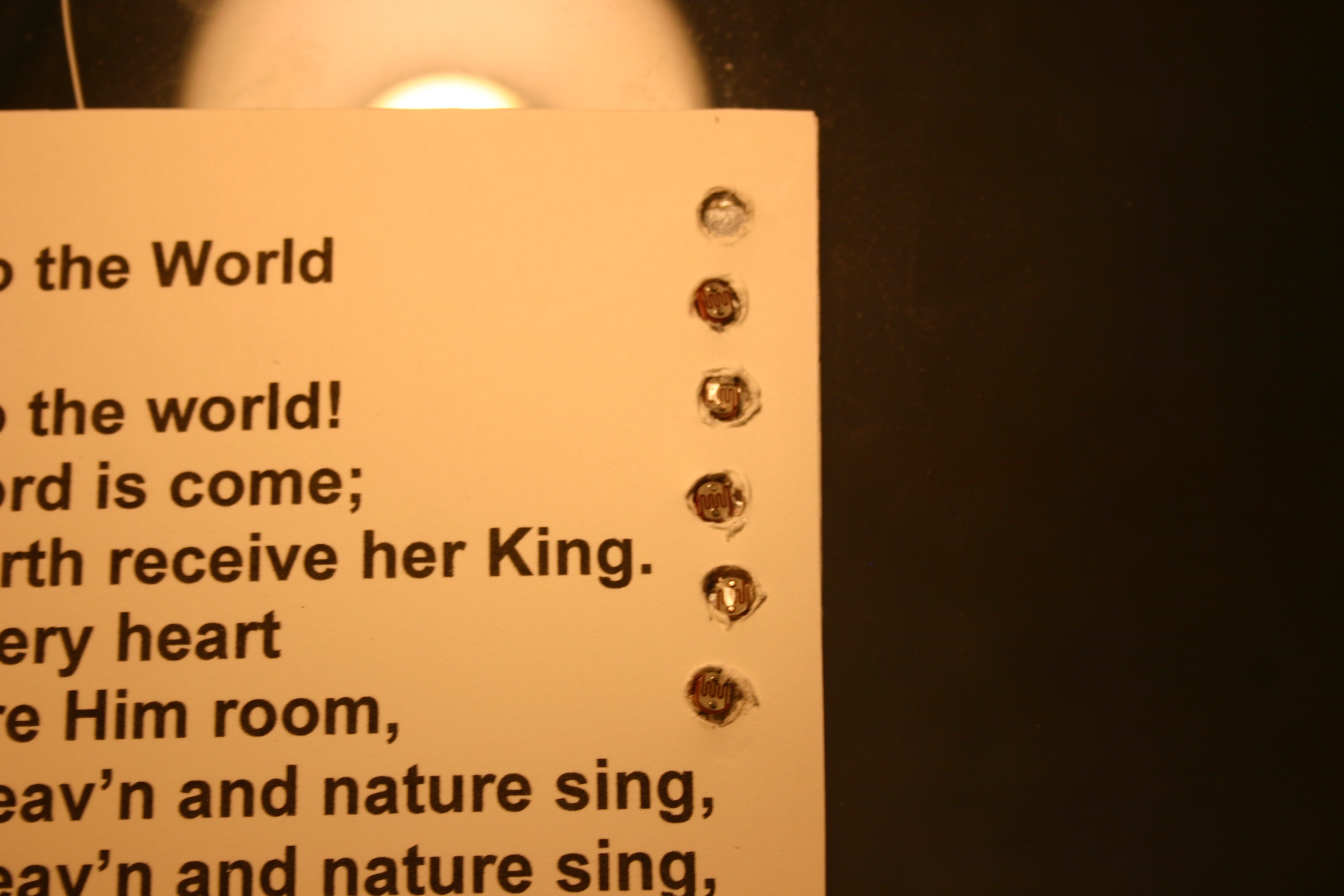
Then I inserted a photo resistor into the hole in the last page of the book.
Metal duct tape was used to secure the photo resistor in place (the sticky side of the tape does not conduct).
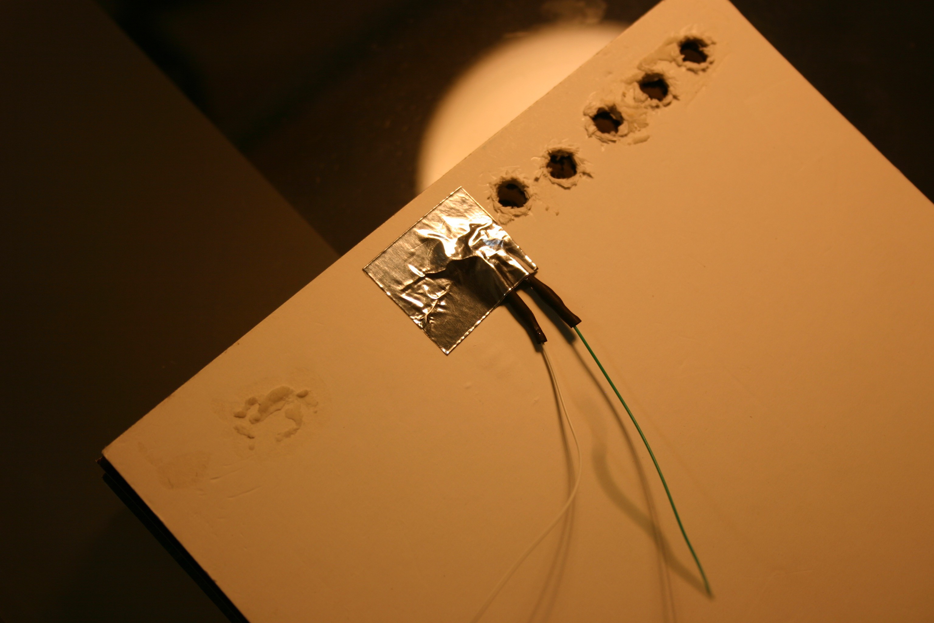
This was repeated for the five active holes.
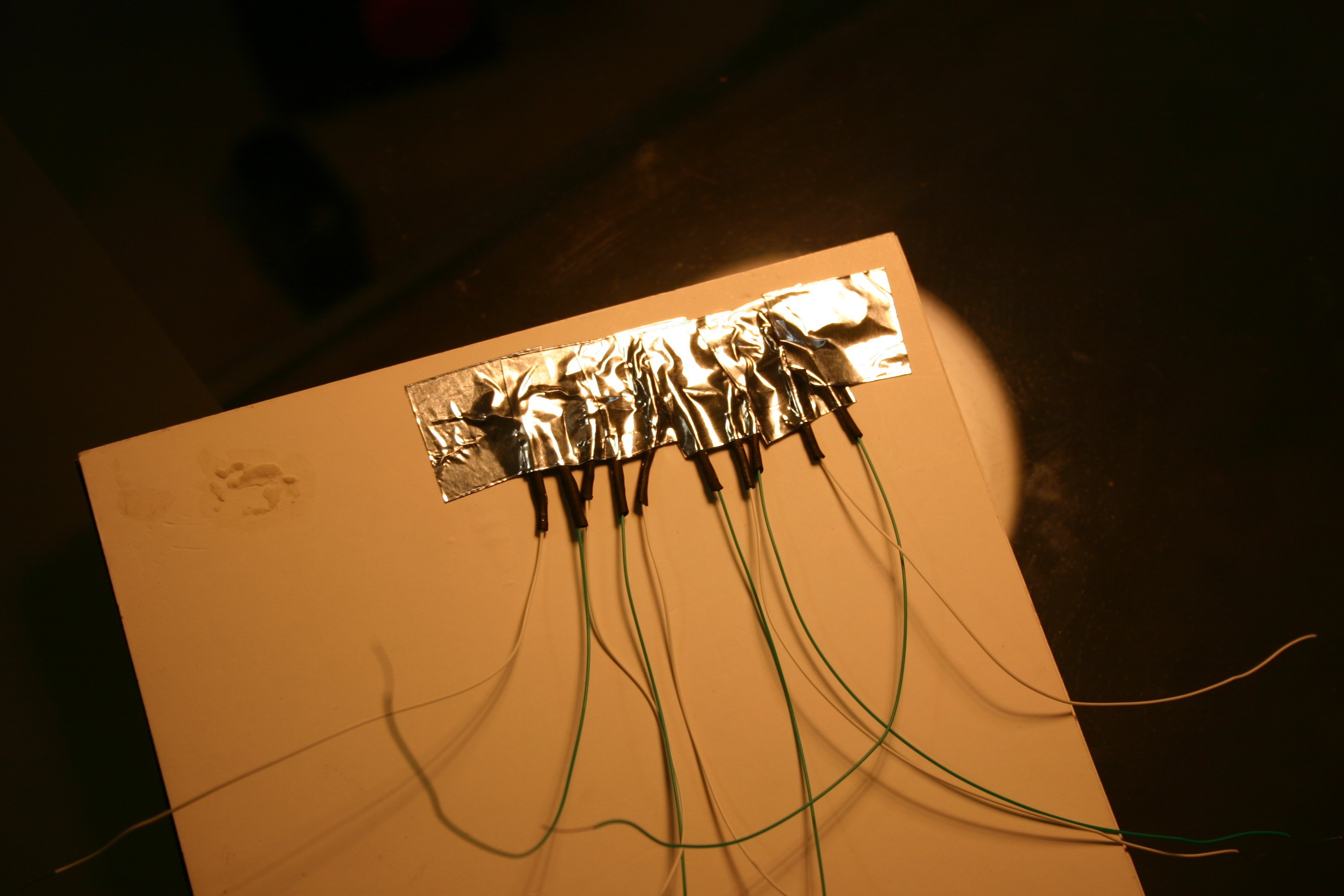
It looks like this from the front side.
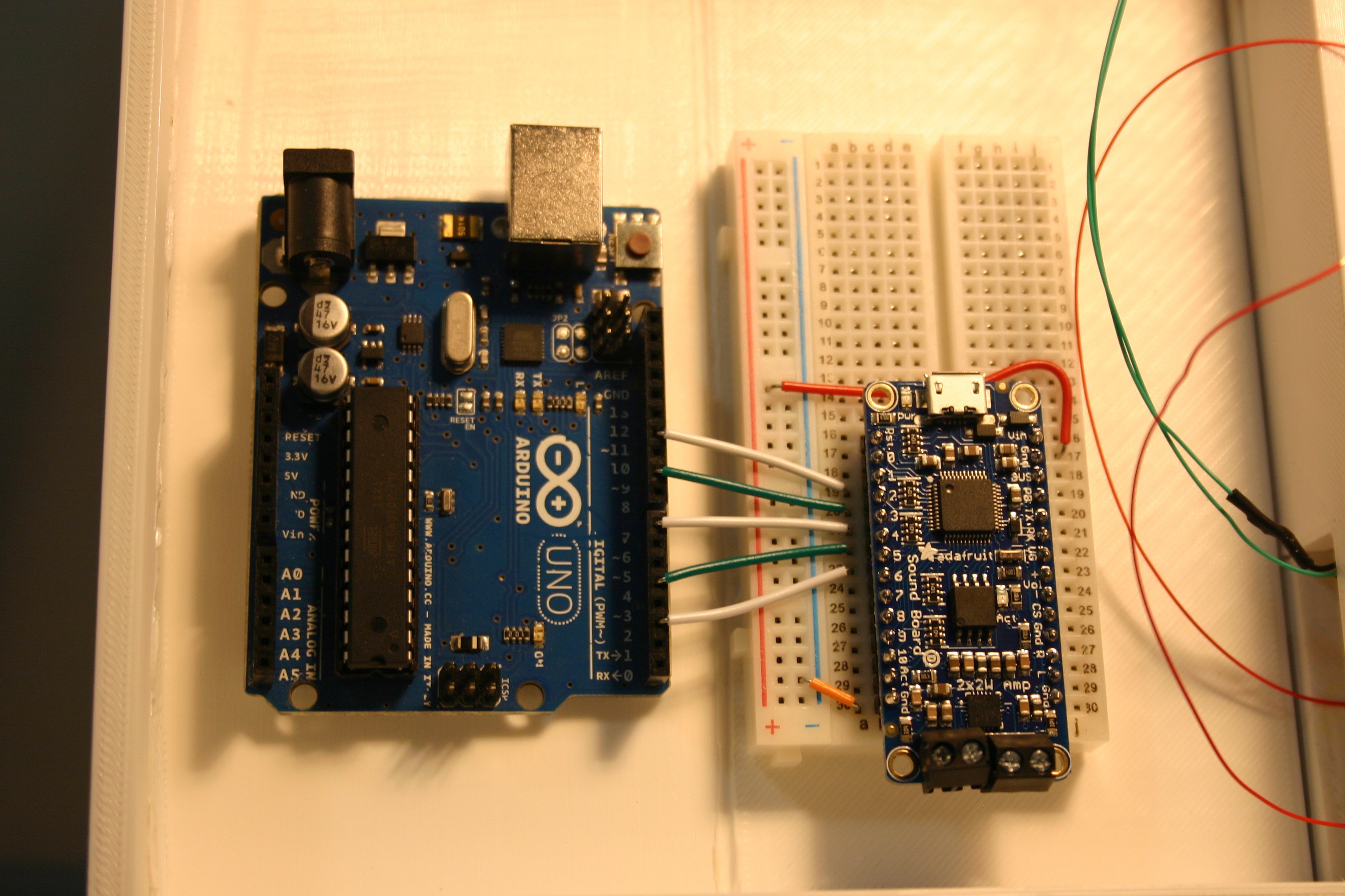
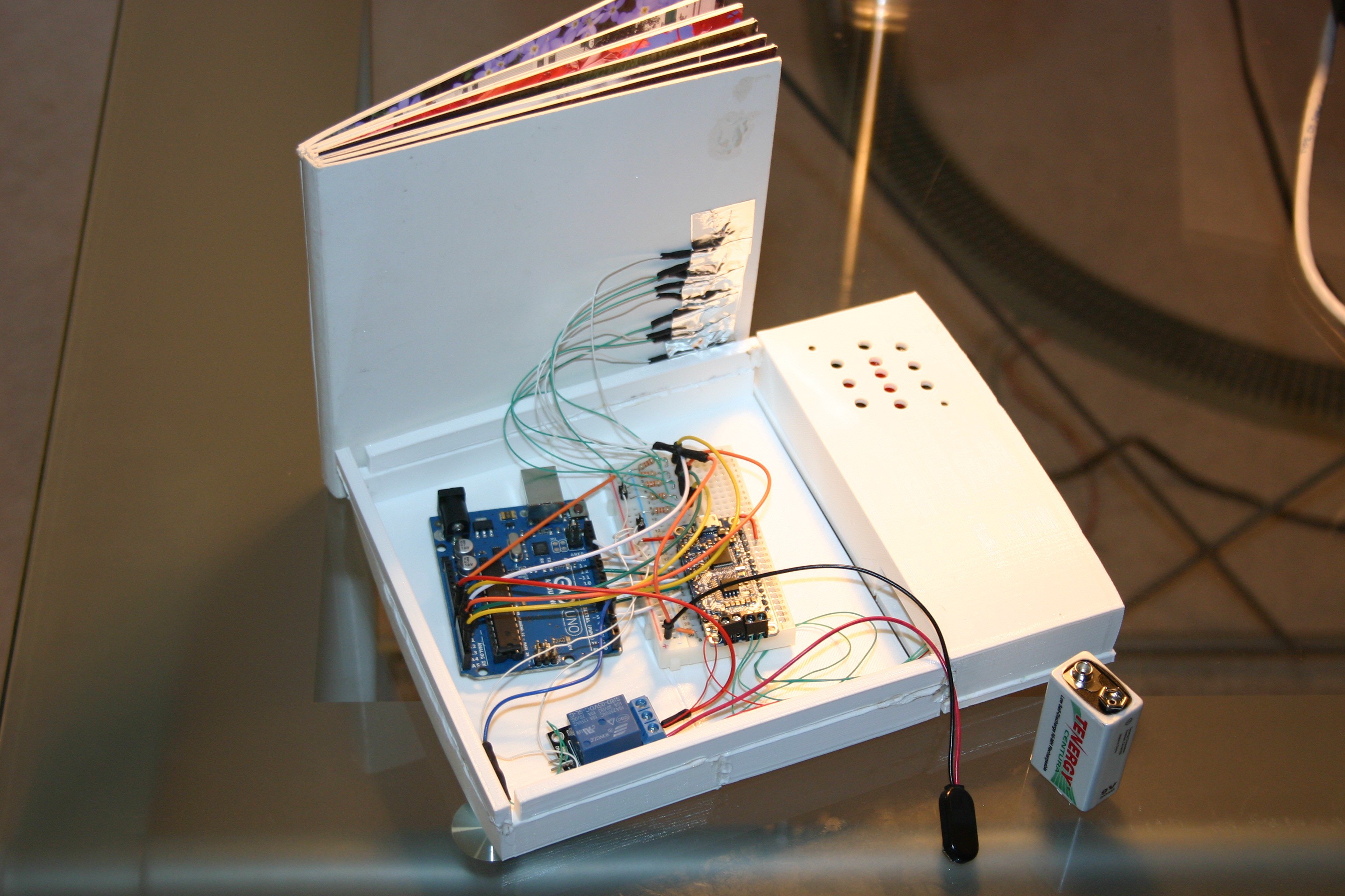
Using the schematic, the Arduino was connected to the Adafruit sound board.
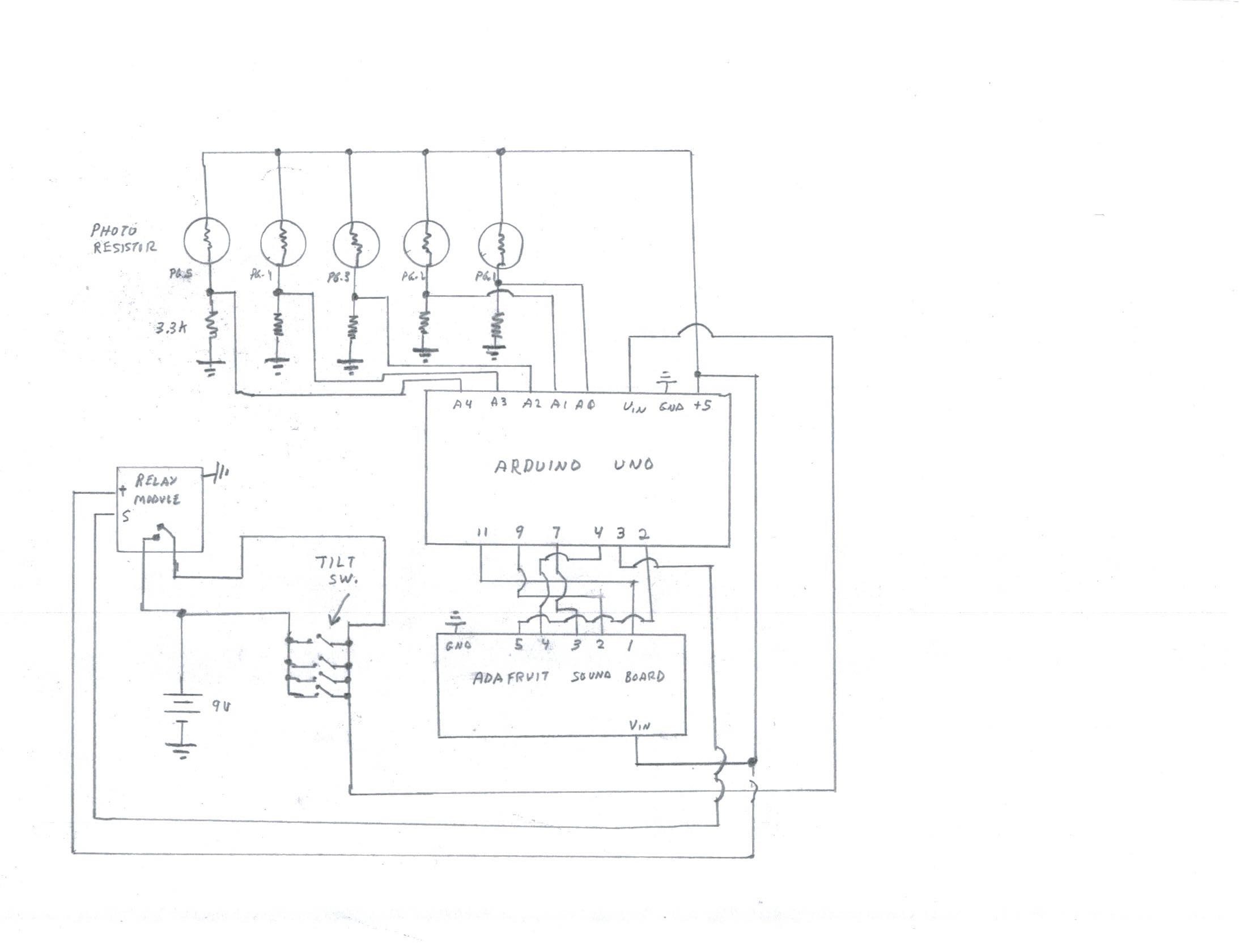
The relay and more Arduino connections are made.
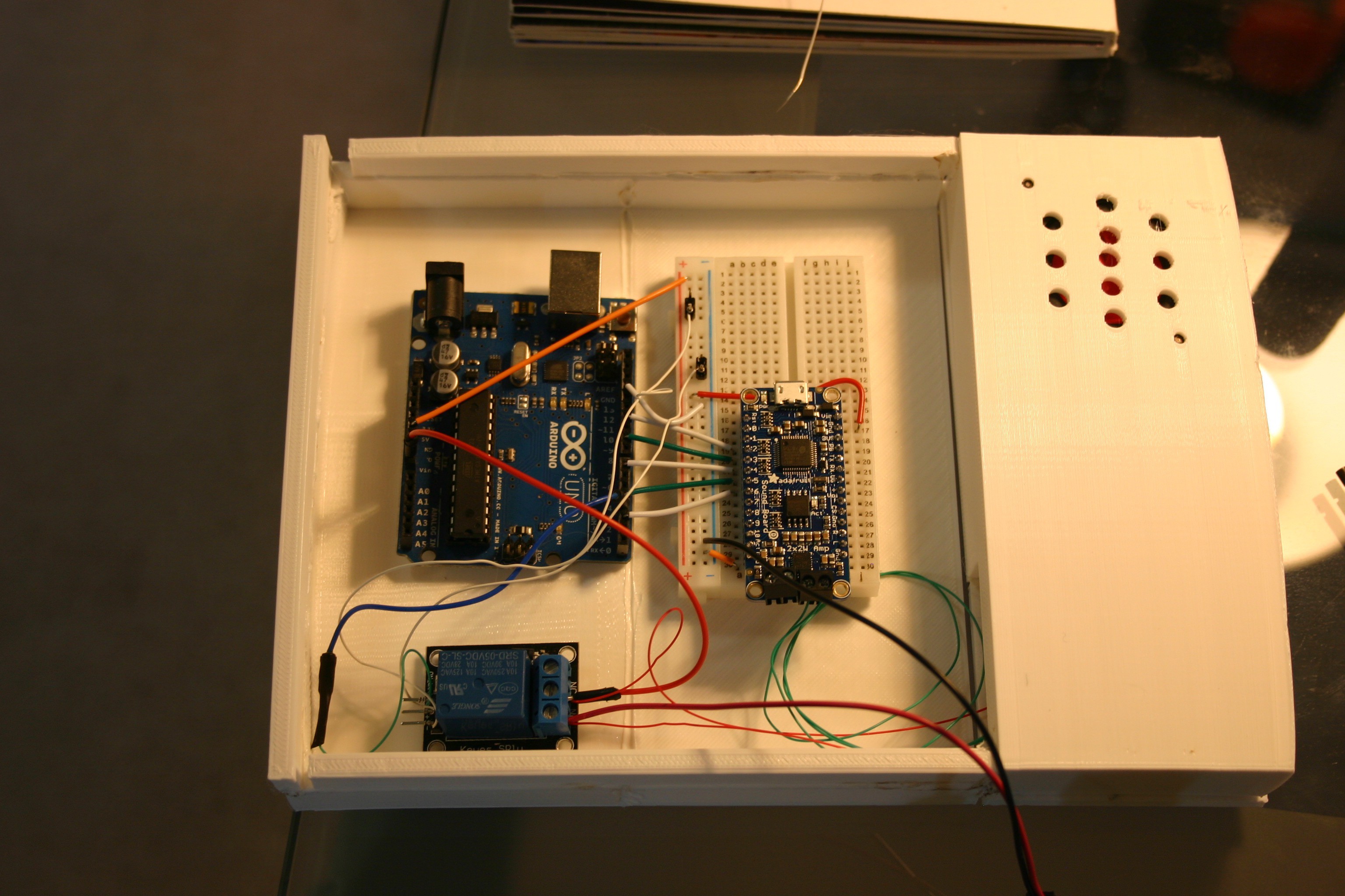
Wires from the photo resistors (the board book) are attached.
Using some sticky putty, the board book was attached to the case (I didn't want things too firmly attached until I have tested the book more completely).

The Arduino sketch for this is included in the files on this site.
Discussions
Become a Hackaday.io Member
Create an account to leave a comment. Already have an account? Log In.