-
Maker Faire
09/12/2017 at 20:09 • 0 commentsThere was a maker faire here in Zürich recently, and one of the more popular projects that I showed off was this. It was by a complete accident, I just grabbed the ears on my way out, but turns out that people really liked to try them on and shot videos of themselves with them.
On the first day I disconnected and re-connected the battery so many times, that I finally broke one of the wires. So in the evening I decided to add a power switch to the board, using one of the small switches I had for the #PewPew FeatherWing. The next day the first thing I did was break that. But no problem, I have a soldering iron with me, I can fix it, right?
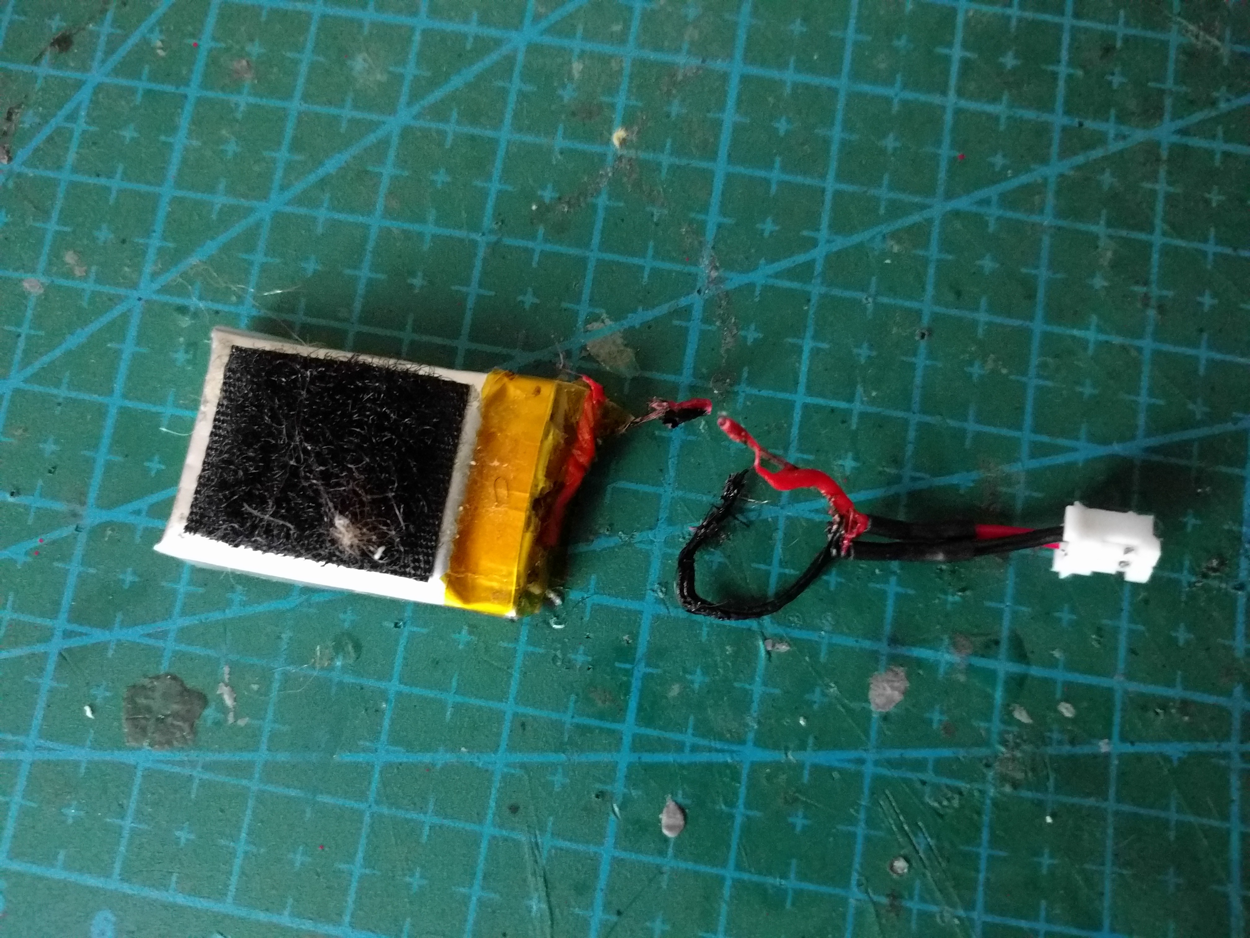
Turns out that soldering when you are half-conscious in the morning and tired after a day of maker faire is a bad idea. I didn't disconnect the battery, and I shorted the leads with my iron, which resulted in this:
![]()
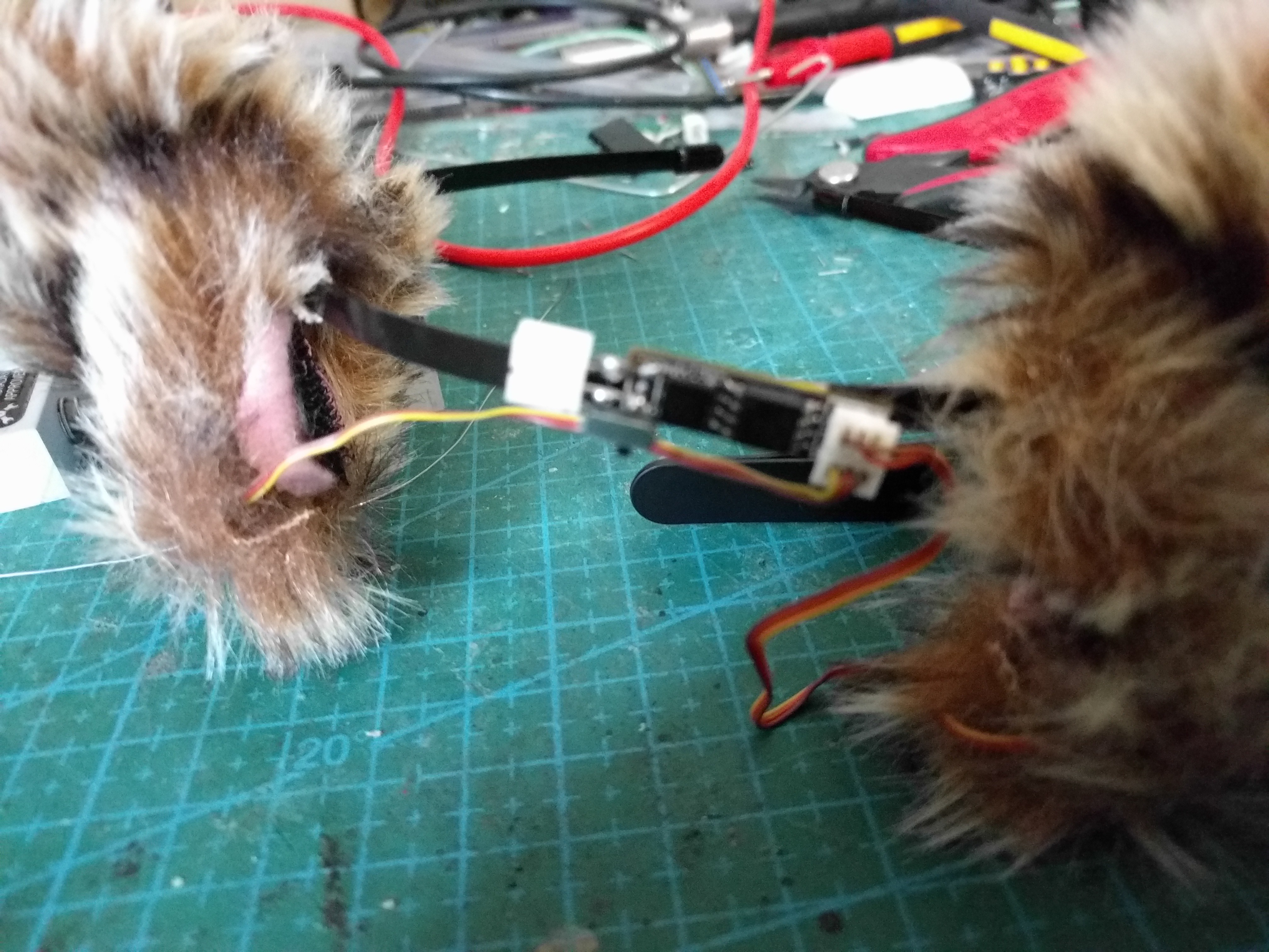
The next day I rescued that battery, and soldered the power switch and the plug in a more permanent way:
![]()
Now I'm thinking about re-doing the PCB with the switch and a LiPO charging circuit built-in...
-
Shrinking
11/26/2016 at 22:30 • 0 commentsOK, now that I've shrunk the code for #Nyan Board to 470 bytes, it's time to look at the code for the ears. This time I'm going to got straight into plain C. All I need to do is to figure out how to do analogRead()... Turns out it's super-simple!
#include <avr/io.h>
#include <util/delay.h>


#define MIN(X, Y) (((X) < (Y)) ? (X) : (Y))


int16_t adc(int8_t pin) {
    ADMUX = 0<<ADLAR | 0<<REFS1 | 0<<REFS0 | pin & 0x03;
    ADCSRA |= 1<<ADSC;
    while (ADCSRA & 1<<ADSC) {
        // Pass.
    }
    return ADC - 512;
}

void update_servos(uint8_t left_position, uint8_t right_position) {
    static uint8_t current_left = 0;
    static uint8_t current_right = 0;

    uint8_t left = 17 + MIN(left_position, 15);
    if (current_left < left) {
        ++current_left;
        OCR0A = current_left;
    } else if (current_left > left) {
        --current_left;
        OCR0A = current_left;
    } else {
        OCR0A = 255;
    }
    uint8_t right = 33 - MIN(right_position, 15);
    if (current_right < right) {
        ++current_right;
        OCR0B = current_right;
    } else if (current_right > right) {
        --current_right;
        OCR0B = current_right;
    } else {
        OCR0B = 255;
    }
}

int running_average(int16_t *buffer, uint8_t *cursor,
                    int16_t *total, int16_t value) {
    *total -= buffer[*cursor];
    buffer[*cursor] = value;
    *total += value;
    *cursor = (*cursor + 1) & 0x0F;
    return *total >> 4;
}

int main () {
    static uint8_t left = 7;
    static uint8_t right = 7;
    static int16_t x_buffer[16] = {};
    static int16_t y_buffer[16] = {};
    static int16_t z_buffer[16] = {};
    static uint8_t x_cursor = 0;
    static uint8_t y_cursor = 0;
    static uint8_t z_cursor = 0;
    static int16_t x_total = 0;
    static int16_t y_total = 0;
    static int16_t z_total = 0;

    // Init ADC.
    ADCSRA = 1<<ADEN | 1<<ADPS2 | 1<<ADPS1 | 1<<ADPS0; // Pre-scaler 128.

    // Output pins PB0 and PB1.
    DDRB = 1<<0 | 1<<1;

    // Setup the PWM clock to ~62.5Hz for the servos.
    TCCR0A = 2<<COM0A0 | 2<<COM0B0 | 3<<WGM00;
    TCCR0B = 0<<WGM02 | 1<<CS00 | 1<<CS01 | 0<<CS02;

    OCR0A = 0;
    OCR0B = 0;

    while (1) {
        int16_t z = running_average(x_buffer, &x_cursor, &x_total, adc(1) - 16);
        int16_t y = running_average(y_buffer, &y_cursor, &y_total, adc(2));
        int16_t x = running_average(z_buffer, &z_cursor, &z_total, adc(3));

        if (x > 20) {
            left = 15;
            right = 15;
        } else if (x < -20) {
            left = 0;
            right = 0;
        } else if (y > 20) {
            left = 15;
            right = 0;
        } else if (y < -20) {
            left = 0;
            right = 15;
        } else {
            left = 7;
            right = 7;
        }

        update_servos(left, right);
        _delay_ms(60);
    }
}
The new code is not as minimalistic as in the case of Nyan Board -- in particular, I'm using much more memory here, for all the running average buffers -- but it's nice and small.
AVR Memory Usage
----------------
Device: attiny85

Program:     484 bytes (5.9% Full)
(.text + .data + .bootloader)

Data:        109 bytes (21.3% Full)
(.data + .bss + .noinit)
-
Make it Fit in 1kB
11/25/2016 at 15:28 • 1 commentI just submitted this project to the 1kB challenge too, because I realized that if I only replace the pinMode calls with a suitable DDRB command, I can get it small enough!
Sketch uses 888 bytes (10%) of program storage space. Maximum is 8,192 bytes.
Global variables use 119 bytes (23%) of dynamic memory, leaving 393 bytes for local variables. Maximum is 512 bytes.
You only need to change the setup() function:
void setup() { DDRB = 1<<0 | 1<<1; // Setup the PWM clock to ~62.5Hz for the servos. TCCR0A = 2<<COM0A0 | 2<<COM0B0 | 3<<WGM00; TCCR0B = 0<<WGM02 | 1<<CS00 | 1<<CS01 | 0<<CS02; OCR0A = 0; OCR0B = 0; } -
Finished
04/17/2016 at 16:47 • 0 commentsSo today I sat down and wrote all the code for the ears. This time I'm using a running average filter to smooth the signal from the accelerometer (because there wasn't any room for capacitors). I also tried to have a drip integrator to measure "excitement" -- just general speed of changes of acceleration -- but that didn't work too well and I went back to the original logic of the ears.
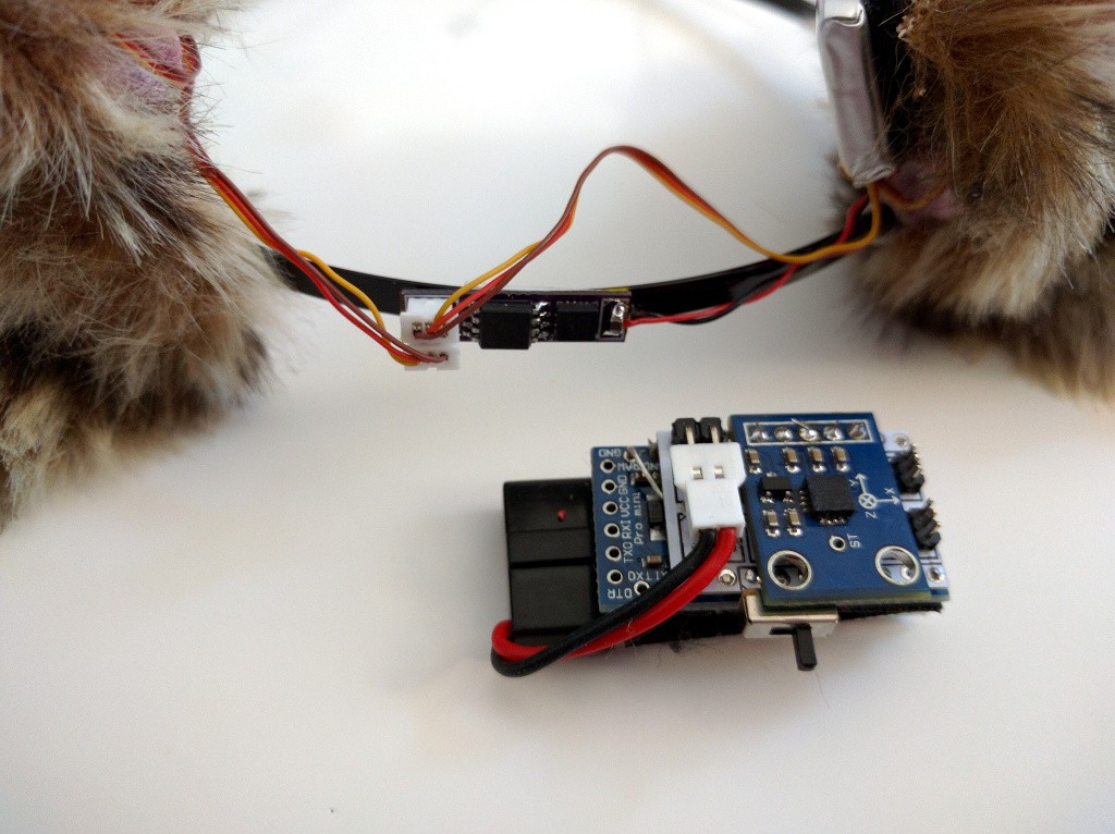
Here's the size comparison of the current model and the initial prototype:
![]()
I guess I could make it smaller if I cut the servo plugs and solder the servos directly, but meh. The battery hides nicely under one of the ears. I should probably wrap the headband with some black tape, to hide the device and the wires, but for now I still want to have access to it.
Here's the code I'm using (the commented out parts are for debugging serial on the servo pins):
//#include <SoftwareSerial.h>


//SoftwareSerial serial(1, 0);


void setup() {
    servo_setup();
    //serial.begin(9600);
}

void servo_setup() {
    pinMode(0, OUTPUT);
    pinMode(1, OUTPUT);

    // Setup the PWM clock to ~62.5Hz for the servos.
    TCCR0A = 2<<COM0A0 | 2<<COM0B0 | 3<<WGM00;
    TCCR0B = 0<<WGM02 | 1<<CS00 | 1<<CS01 | 0<<CS02;

    OCR0A = 0;
    OCR0B = 0;
}

void update_servos(uint8_t left_position, uint8_t right_position) {
    static uint8_t current_left = 0;
    static uint8_t current_right = 0;

    uint8_t left = 17 + min(left_position, 15);
    if (current_left < left) {
        ++current_left;
        OCR0A = current_left;
    } else if (current_left > left) {
        --current_left;
        OCR0A = current_left;
    } else {
        OCR0A = 255;
    }
    uint8_t right = 33 - min(right_position, 15);
    if (current_right < right) {
        ++current_right;
        OCR0B = current_right;
    } else if (current_right > right) {
        --current_right;
        OCR0B = current_right;
    } else {
        OCR0B = 255;
    }
}

int running_average(int *buffer, uint8_t *cursor, int *total, int value) {
    *total -= buffer[*cursor];
    buffer[*cursor] = value;
    *total += value;
    *cursor = (*cursor + 1) & 0x0F;
    return *total >> 4;
}

void loop() {
    static uint8_t left = 7;
    static uint8_t right = 7;
    static int x_buffer[16] = {};
    static int y_buffer[16] = {};
    static int z_buffer[16] = {};
    static uint8_t x_cursor = 0;
    static uint8_t y_cursor = 0;
    static uint8_t z_cursor = 0;
    static int x_total = 0;
    static int y_total = 0;
    static int z_total = 0;
    static int excitement = 0;

    int z = running_average(x_buffer, &x_cursor, &x_total, analogRead(1) - 512 -16);
    int y = running_average(y_buffer, &y_cursor, &y_total, analogRead(2) - 512);
    int x = running_average(z_buffer, &z_cursor, &z_total, analogRead(3) - 512);

/*
    serial.print(x);
    serial.print(", ");
    serial.print(y);
    serial.print(", ");
    serial.print(z);
    serial.println();
*/

    if (x > 20) {
        left = 15;
        right = 15;
    } else if (x < - 20) {
        left = 0;
        right = 0;
    } else if (y > 20) {
        left = 15;
        right = 0;
    } else if (y < -20) {
        left = 0;
        right = 15;
    } else {
        left = 7;
        right = 7;
    }


    update_servos(left, right);
    delay(60);
}
And that's it for this project. Works as intended.
In the future, I might try and make a hat with ears, using larger servos and putting everything inside the hat.
-
Servos Hate Grease
04/16/2016 at 22:36 • 0 commentsSo I also made an attempt at making those servos a little bit more quiet. I opened one of them, and filled it with some servo grease that I ordered from China some time ago. Assembled it back together, and...
Turns out the servo is perfectly quiet now. Unfortunately, that's because it doesn't move.
Turns out that the smallest gear -- the one near the motor -- has to move with such ease, that even a little bit of grease makes it completely stuck. It took me about an hour to clean all the grease from those gears, and the servo works again. As loud as before, though.
-
Assembled, Programming
04/16/2016 at 20:17 • 0 commentsSince all my "current" projects are either waiting for parts, or being punished for not going the way I wanted, I decided to finish this one. I started with connecting all the wires to an ATTiny85 I have soldered to a breakout board. Turns out that the accelerometer connected to the chip's pins doesn't prevent it from being programmed! Yay, that means I can just solder the chip in place and re-program it with a clip.
![]()
Next step, I made some connectors for the servo sockets, so that I can use SoftwareSerial on them for debugging. In particular, I needed to check what are the rangers on the accelerometer readings. Turns out that "0" is smack in the middle of the range, at 512, and 1g is about 100 units. Good enough.
Next I will need to check the servo's limits (since I'm not using exactly 50Hz for PWM, they will be different) and actually write the code for the ears-moving logic... I guess for that last part, I will still use the Pro Mini-based prototype. It's simply easier to reprogram.
-
Hot Plate Soldering
03/21/2016 at 10:43 • 1 commentThe PCBs that I wrote about last time were not the real PCBs. OSHPark has made a mistake in the board thickness (a new option that they have), and sent me the boards again, this time thinner. I didn't realize that, so I was quite surprised to see the second shipment, but all is good.
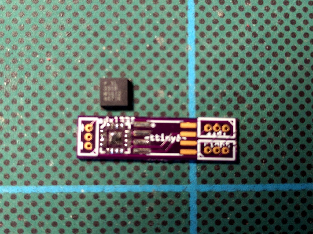
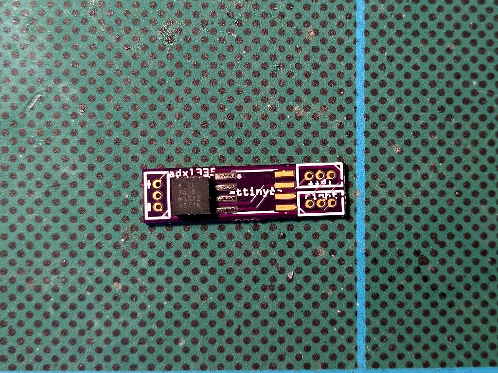
The GY-61 breakout kit also arrived, so I'm ready to try and solder it on that board. This is a "LFCSP LQ" surface-mount package, so impossible to do with a hand soldering iron. At the hackaday channel someone suggested using a kitchen stove, so I have that a try. First, I tinned the board:
Then I covered it in flux, and went to the kitchen. I have an electric stove with a glass top, so I put the board directly on it, and heated it until the solder melted. Then I carefully placed the chip on the right spot, and pressed it gently down. Finally, I removed the whole thing from the stove.![]()
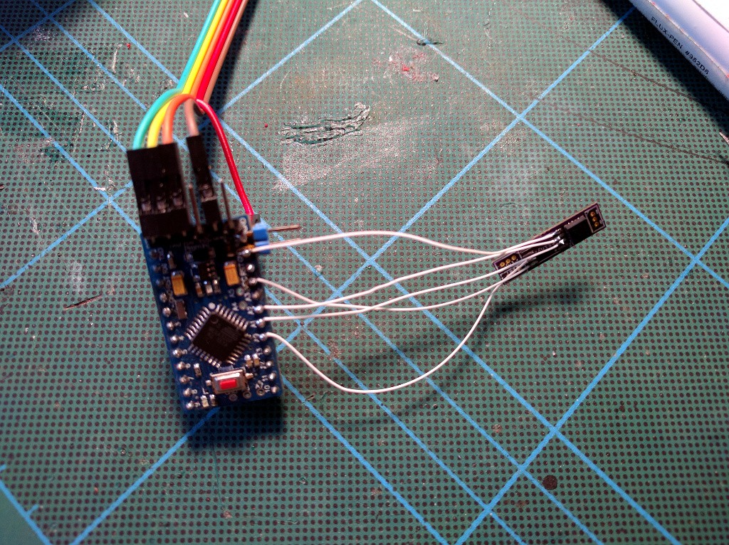
Next, time for a test. I didn't want to solder an attiny85 on the board just yet, because it's inconvenient to debug with it, so instead I connected a 3.3V Pro Mini with some kynar wire:![]()
Note that the VCC cable from USB2TTL is connected to the RAW pin, not to the VCC pin on the FTDI header, because I don't want 5V on the VCC pin...![]()
A quick sketch lets me verify that the thing works!
void setup() {
    Serial.begin(115200);
}

void loop() {
    Serial.print(analogRead(A0));
    Serial.print(", ");
    Serial.print(analogRead(A1));
    Serial.print(", ");
    Serial.print(analogRead(A2));
    Serial.println();
    delay(300);
}
Now I just need to figure out what are the center values when powered with the battery I want, and write the program.
-
PCBs Arrived
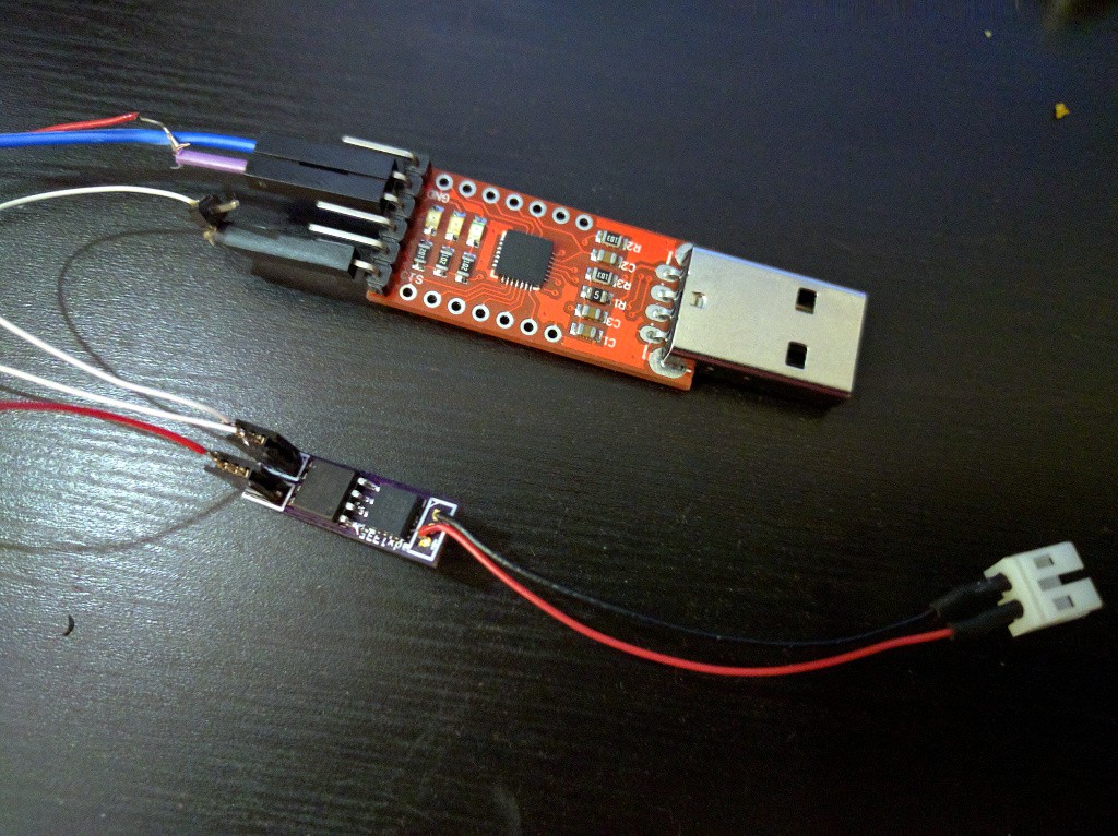
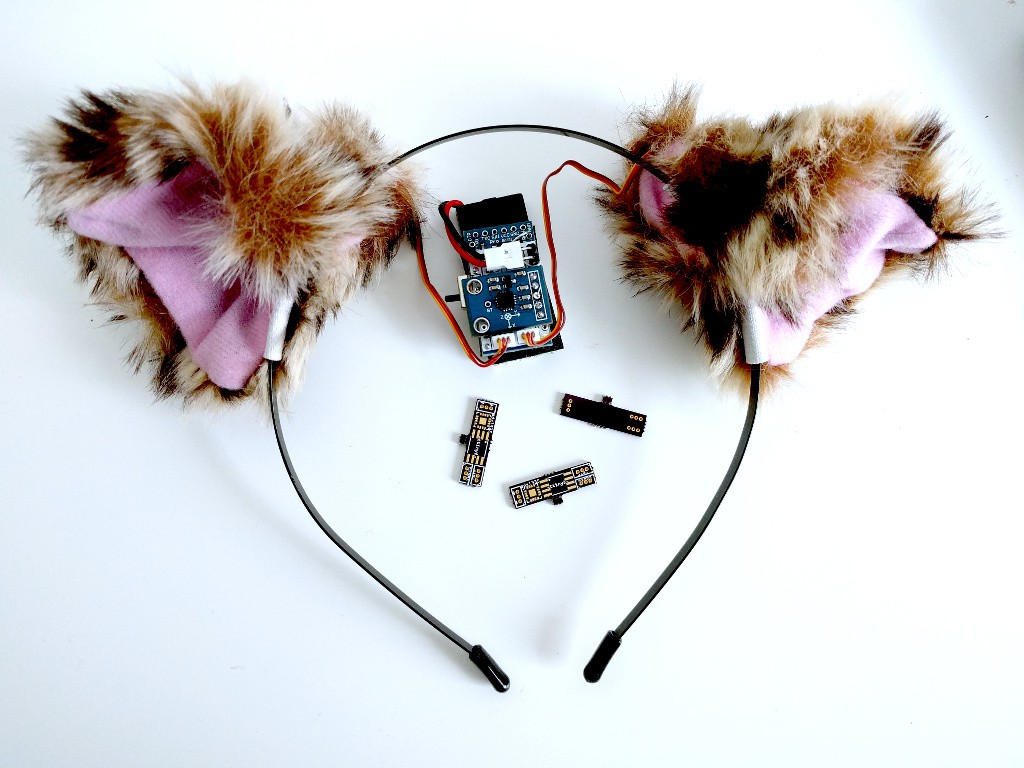
03/09/2016 at 09:29 • 0 commentsToday the printed circuit boards arrived from OSHPark. I'm still waiting for the accelerometer chip (it will be fun to solder it), though. Here's the size comparison between the new PCBs and the old prototype:
![]()
-
PWM on ATtiny85
02/23/2016 at 22:05 • 3 commentsSo I decided to go for this miniaturized version, and ordered the PCB at OSHPark. Since it was so small, it's quite cheap. But that means that now I need to port my code to ATtiny85. I can use an Arduino core, but I still need to come up with a way to control the hobby servos. The obvious way is to use Fast PWM mode.
The usual way to do it is to set a timer with two triggers -- one that switches the pin low, and one that resets the counter and switches the pin back to high. This gives you precise control over the exact frequency and duty cycle of the signal. ATtiny85 has two such timers, so I should be all set.
There is a small problem, however. I will also need 3 ADC pins, and one of those is the same as the Timer1 PWM pin. There is an ADC on the reset pin too, but I don't have a high voltage programmer to make use of that. So I can't use the second timer.
What I can do, is to use Timer0 but don't reset it on the second trigger, but let it overflow. Then use the second trigger for the second PWM pin. That however removes the precise control over the frequency -- now I can only use the frequencies that are available with the given prescalers and CPU speeds. Turns out I can do 62.5Hz with the ATtiny85 at 1Mhz. This is close enough for most servos.
With some diving into the datasheet and a bit of experimenting, I came up with this code:
void setup() {
    pinMode(0, OUTPUT);
    pinMode(1, OUTPUT);

    // Setup the PWM clock to ~62.5Hz for the servos.
    TCCR0A = 2<<COM0A0 | 2<<COM0B0 | 3<<WGM00;
    TCCR0B = 0<<WGM02 | 1<<CS00 | 1<<CS01 | 0<<CS02;

    OCR0A = 0;
    OCR0B = 0;
}

void loop() {
    for (int i=10; i<30; ++i) {
        OCR0A = i;
        OCR0B = i;
        delay(100);
    }
}
Note that since I'm messing with Timer0, which is also used by the Arduino core to keep track of millis(), the delay() is no longer accurate. But I can live with that.Here's the servo in action:
-
Miniaturization
02/21/2016 at 09:43 • 0 commentsSo I've been thinking... If I were to do it seriously, I would probably drop the Pro Mini and use an ATtiny85 instead, with a custom, small PCB to contain the whole thing. It would be small enough to actually fit on the band holding the ears, something like this:
![]()
That's 23×6.5mm, and could be made even smaller if I populated both sides... Then of course the battery would need to go into one of the ears, and there also needs to be a power switch...
 deʃhipu