 Yann Guidon / YGDES
-
Oscillation coupling
02/21/2016 at 18:31 • 0 commentsMy first test has not shown a significant period variation when the LDR is lit or shadowed, I wonder what is the best placement for the light-sensitive resistor. I'll have to build a few boards and test them...
OK, let's do this :-)
OK it seems I must engineer the system better. I made a 2nd circuit and they seem to naturally work at different frequencies. They appear to "read" each other when placed close but there is a weird 4:5 frequency ratio. I'm not sure if the feedback keeps the pulses in sync or prevents them, though I see they seem to lock for a cycle or two and then....
I must analyse the phase behaviour. And/or design a phase detector, or something.
-
First blink
02/20/2016 at 22:40 • 0 commentsSome prototyping and it's done !
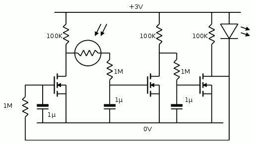
![]() There is something strange with the CMOS inverter: the circuit does not work when a BS250 replaces the 100K pull-up. The mystery is still complete.
There is something strange with the CMOS inverter: the circuit does not work when a BS250 replaces the 100K pull-up. The mystery is still complete.Another hickup is the pull-up in parallel with the LED: without it, the LED drop does not allow the next gate to rise high enough to propagate the wave. That's why the original circuit worked at 6V...
I try to make it as efficient as possible so I'll increase the resistances even more.
There is no series resistance with the LED because it's a 1W model (can easily stand 200mA), it normally works at about 3.2-3.5V and the scope shows the maximum drop is 0,3V, so the peak LED voltage is around 2.7V is short bursts. No heat is generated.
Power consumption without the LED is about 50µA, I replaced the 100K pull-ups with 330K and it drops to 18µA peak (10µA in average ? I can't measure slow currents in RMS). This is very low, the LED consumes much more current, and the higher resistances slow down the transitions...
Now, WHY does the circuit stall when the BS250 replaces the pull-up resistor ?
Yet Another Electronic Lampyridae
and I ain't using a '555. Self-organising CMOS ring oscillators are cooler !
 There is something strange with the CMOS inverter: the circuit does not work when a BS250 replaces the 100K pull-up. The mystery is still complete.