Yann Guidon / YGDES
-
Virtual Lampyridae
04/19/2025 at 12:46 • 0 commentsCircuitJS has progressed considerably since the last logs.
Here you can play with the simulation, which I can adjust to run in real time !
![]()
-
Board v.3
09/05/2016 at 18:09 • 0 commentsThe new version simply adds a footprint for a CR2032 battery holder on the backside. I had to reshuffle things a bit and I corrected tiny blunders. Here is the result :-)
![]()
I don't know yet when I'll send it to factory.
-
Board v2 has been delivered
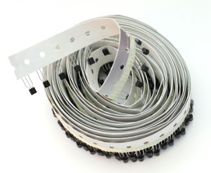
08/03/2016 at 18:23 • 0 commentsThe PCB has been manufactured by DirtyPCB (along with the 10TFF modules) and the results are pretty nice :-) I should now test the solderability but I don't worry about it. I'll use these boards for soldering workshops.
![]()
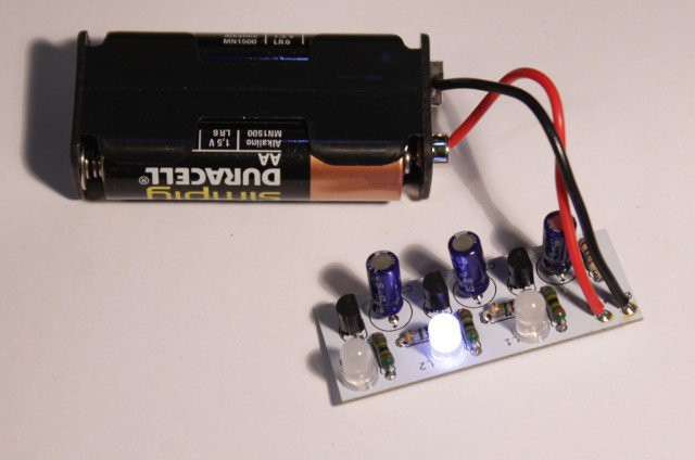
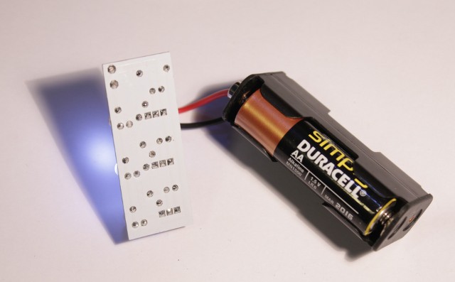
Update 20160805:
Soldering was a breeze and 5mm LEDs also work instead of 3mm LEDs (I should add a polarity sign to the LED though). The circuit worked right away when powered on !
![]()
![]()
You can watch a video there : https://www.facebook.com/YGDES/videos/1131949946899923/
-
Board v2
07/08/2016 at 03:05 • 0 commentsI tuned the layout, using the experience from the #Yet Another (Discrete) Clock 10TFF module.
For example, I enlarged the pads of the standard parts to ease soldering. Plated holes help soldering too but the larger pads allow more heat transfer.
I reduced the size to 50×20mm to make it easy to manufacture. You can fit 2×8 boards on a 160×100 (Europe) format, or 2×5 on a 10×10mm format.
I added 2 LEDs because they help check the circuit progressively, during soldering.
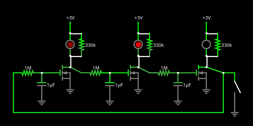
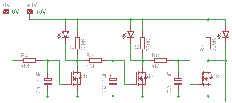
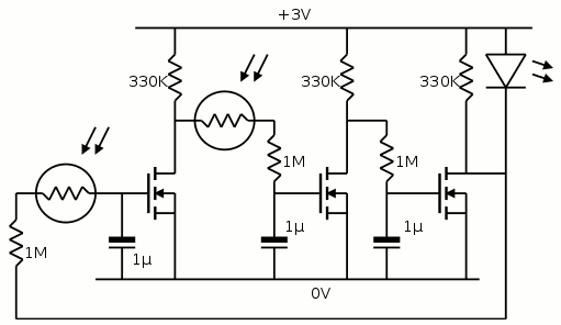
The schematic is barely changed :
![]()
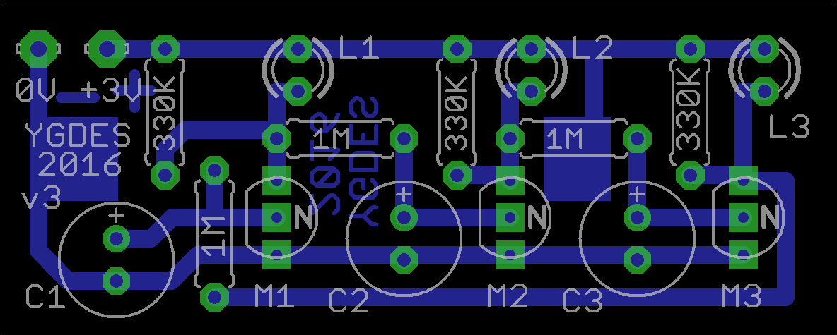
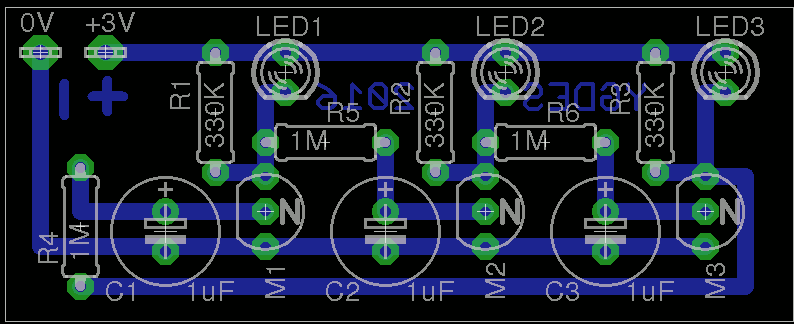
The layout is much better, though:
![]()
Hopefully, it is not too intimidating to beginners.
Another enhancement would be to add a Lithium coin cell footprint, to replace the 2 pads for an external power supply.
-
Today a boy made me feel proud
05/28/2016 at 23:46 • 0 commentsAs I hold workshops, I'm learning as much as the kids do. I would like to bring more and be in tune with them, so they get the best possible experience and perspectives. And today I asked a kid what he remembers from the circuit that I have explained.
"We can make a LED blink without using an Arduino."
Priceless.
He will turn 11 in a few days and he got the essence of my message !
-
My first group course at LOREM
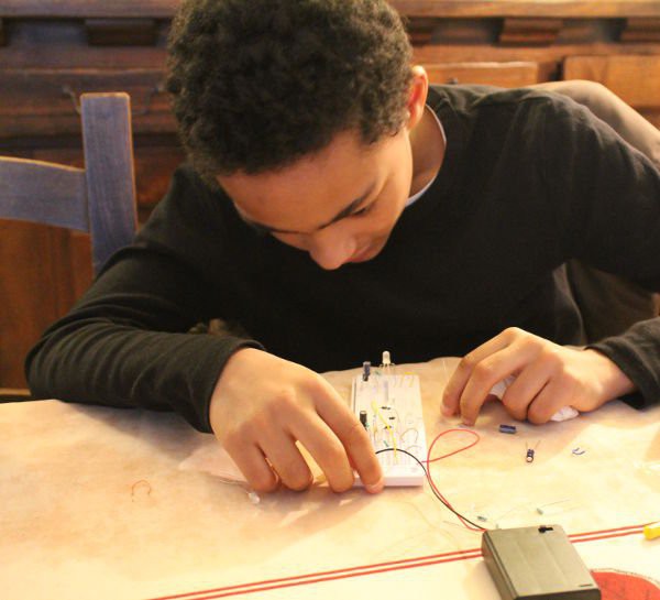
05/15/2016 at 05:00 • 0 commentsI have made my first workshop with the kids and we have had a great time !
Saturday afternoon (20160514) from 2PM until 6PM, I have explained, shown, demonstrated, how the few components of the MOSFET ring oscillator work. That's the resistor, potentiometer, the LED, the capacitor and the P-MOSFET. I started with the obligatory reminders about electricity, breadboards and how to use a multimeter.
After 2 hours, most of the circuits worked as expected ! Errors always happen (even I make them often) but thanks to a very progressive, careful and simple method, small errors are easily and quickly identified and solved. No magic smoke has been released, no tear has been shed!
I am thankful to all the people at LOREM for their enthusiasm, patience, trust and curiosity. Some of the kids are pretty skilled (not just boys) and this is very encouraging. I'll return with this workshop and even more (wink wink) as soon as I can!
-
First layout
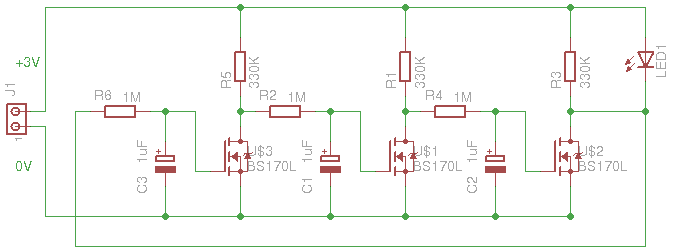
04/13/2016 at 08:21 • 0 commentsThe schematic has just been entered into EAGLE!
![]()
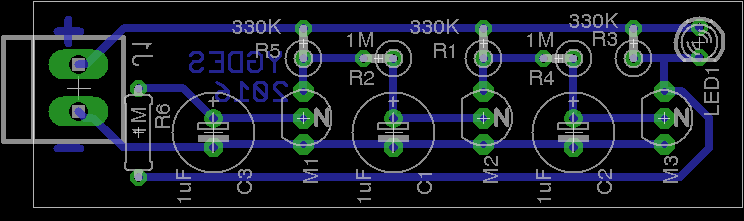
That circuit is really easy and quick to route. Here's the 2cm×6cm result with wide margins for newbies :
![]()
I'll try to make 10 or 20 but the size does not let it fit in 5cm or 10cm square boards. I'll have to find a trick. Parts can be densely packed but that would not keep its beginner-fdriendliness.
-
Family Fun !
03/02/2016 at 00:29 • 0 commentsNephew got introduced to MOSFETs today !
![]()
One MOSFET didn't survive but "that's the price of education". And it's not as if I was about to run out of BS170 tomorrow...
![]()
And today, an 11-years (and his younger sister) old learned about resistors, capacitors and transistors :-)
-
Locking to bi-alternance
02/23/2016 at 09:16 • 0 commentsI think I understand better what happens.
The LEDs lock in either of 2 groups of opposite phases.
Whenever I remove one that is alone in a group, some other will try to take its place/phase.
It's more obvious when they are all started up at the same time: the LDR are in series with the charge capacitors' resistors. So in the dark, the oscillations don't start.
The circuits need light to oscillate !
The first LED that starts to emit light will trigger an avalanche and the others will turn on too, but with a little delay. There is already a phase shift and the first LED will oscillate thanks to the light of the others. And vice versa.
Maybe I should add a 5M Ohms resistor across the LDR pins...
but this will not solve the problem : there will still be 2 groups.
-
Coupled oscillations
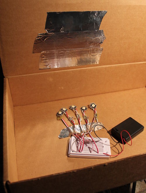
02/23/2016 at 05:48 • 0 commentsI made a little test system for the 5 fireflies I just soldered. I made them run and I noticed a strange behaviour : they tend to oscillate by groups, so there IS coupling, however they usually make 2 alternating groups.
![]()
I installed the circuits inside a cardboard box, with alu tape over them to increase reflection of their own light.
The coupling is quite strong since a few cycles are enough to sync them... except that they tend to split into 2 groups (including one circuits that jumps from one group to another, maybe one of the parts is not the right value, or differently lit ?). Anyway, when they sometimes all turn on in sync, it's pretty powerful :-)
Then it struck me: the light sensor is active during one part of the cycle only...
I'll try to add another LDR in series with another 1M resistor, to cover another phase. I'll have to try different configurations to find the one that works best...
![]()
Yet Another Electronic Lampyridae
and I ain't using a '555. Self-organising CMOS ring oscillators are cooler !