A VGA signal has two wires for Hsync and Vsync. Hsync is a short pulse that goes off at the end of a scanline to tell the raster beam to go back to the left of the screen, drop down a pixel, and start drawing a new scanline. Vsync is a longer pulse that goes off when the raster beam is in the bottom right corner to tell it to move to the top left corner and start drawing the screen again from the beginning. The sync signal timing must be constant and match the VGA standard.
I decided to use a 640x480 60Hz signal.
*the 640 is pretty meaningless to this project because an analog video synth doesn't use horizontal pixels.
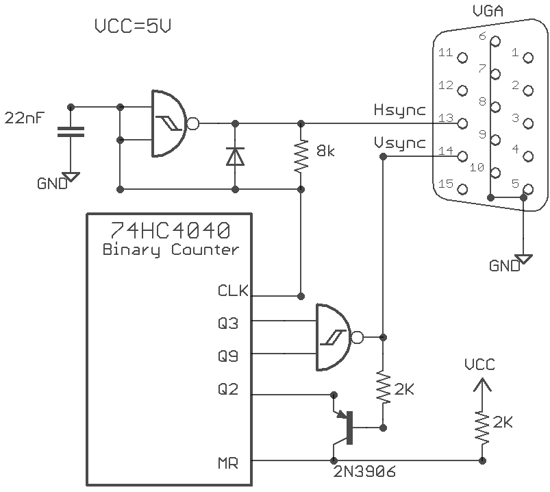
I could have taken the Sync signals from my computer's VGA output, but I wanted this project to be self-contained. I've generated VGA signals with microcontrollers and FPGAs in the past, but I've been relying on those too much lately and decided to do it in discrete logic this time. I put a lot of thought into keeping part count and complexity down and realized I could do everything with a 74HC4093 (Quad 2-input NAND schmitt) and a 74HC4040 (Binary Counter).

The Hsync pulse is generated by producing a Schmitt relaxing oscillator with one of the 4093's gates. The HSync pulse of a 640x480-60hz VGA signal has a frequency of 31.5 kHz. The signal is normally high, and pulses low for 3.8µs. In my circuit when the gate output is high it travels through the 8k resistor and charges the 22nF capacitor. When the 22nF capacitor is charged to 2/3 Vcc the gate output switches to low then very quickly discharges the capacitor to 1/3 Vcc and starts the cycle over again. I could have put a resistor in series with the diode to control the width of the low pulse, but no resistor was very close to the ideal 3.8µs.
The Vsync pulse needs to go off every 525 Hsync pulses. It's not 480 because there are 45 extra hidden lines in a VGA signal used to give the raster beam time to get into position. I use a binary counter to count the Hsync pulses. After 520 Hsync pulses the Vsync pulse is activated. After 524 pulses the counter resets which turns of the Vsync pulse. This logic is implemented with one of the NAND schmitt gates (behaving like a regular NAND) and a PNP transistor.
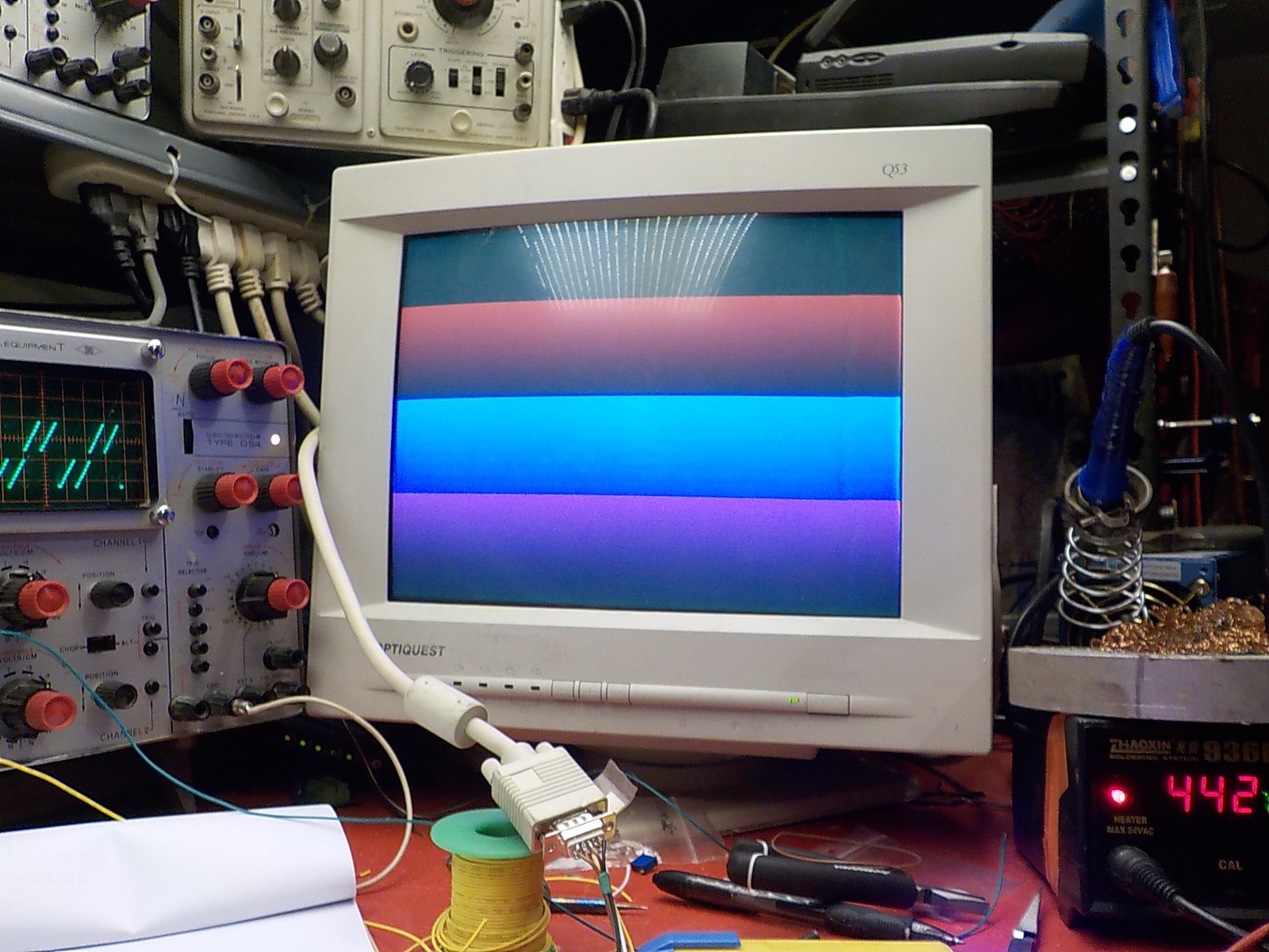
With this circuit I can get the VGA monitor to turn on. The horizontal bars in this image are produced by running some of the binary counter's outputs to the RGB VGA inputs. The bars are very faint because I haven't implemented porching yet.
 Russell Kramer
Discussions
Become a Hackaday.io Member
Create an account to leave a comment. Already have an account? Log In.
This circuit will not work. There are many things that will go wrong.
1-The oscillator is voltage/temperature/..etc sensitive .. i.e. it is not accurate and will never be a good choice.
2-The MR Signal at the the start is high which results in stopping the counter .ie. the counter will never start ..i.e. the vsync will never generates.
Anyway, you need to have a crystal oscillator .. but how to generate the hsync shape? It is not easy.
I tried the circuit and it is not functioning .. I fixed the PNP transistor to let the counter start.. but the V signal didn't work either ..etc.
Are you sure? yes | no
thanks but how did you get the horiontal bars ? did you use memory to save the RGB data?
Are you sure? yes | no
The 4040 binary counter goes from 0b000000000 to 0b1000001101 as the screen is drawn and has outputs for each bit. The count goes up by 1 every scanline. Connecting the binary outputs to the R,G,B wires will make the lines different colours. The black,red, blue, and purple stripes were produced by R to bit 7 and B to bit 8. 00 -> 01 -> 10 -> 11 = black -> red -> blue -> red + blue
Are you sure? yes | no
hello ! i just want to know if the number 525 depend on the type of screen that we use or the resolution ?
Are you sure? yes | no
525 is the number of scanlines in a 640 x 480 VGA signal. Almost all VGA monitors will accept this resolution.
Are you sure? yes | no