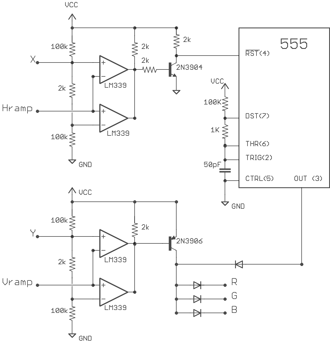
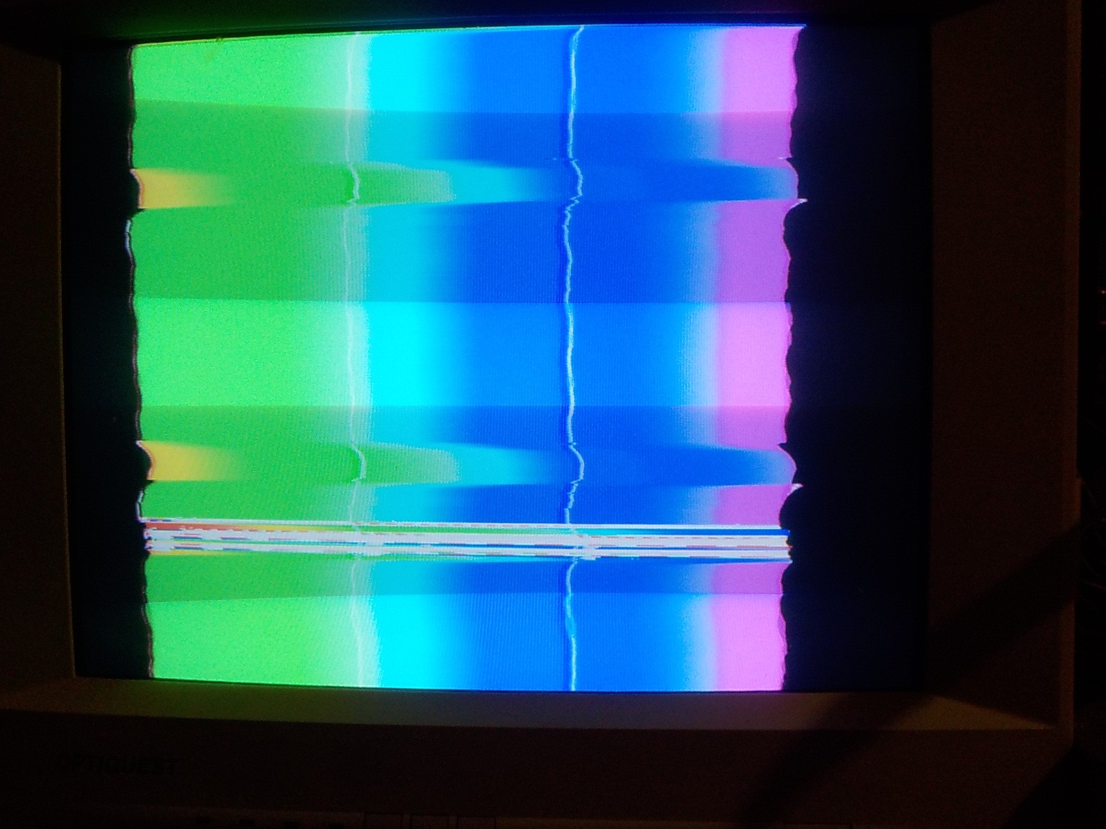
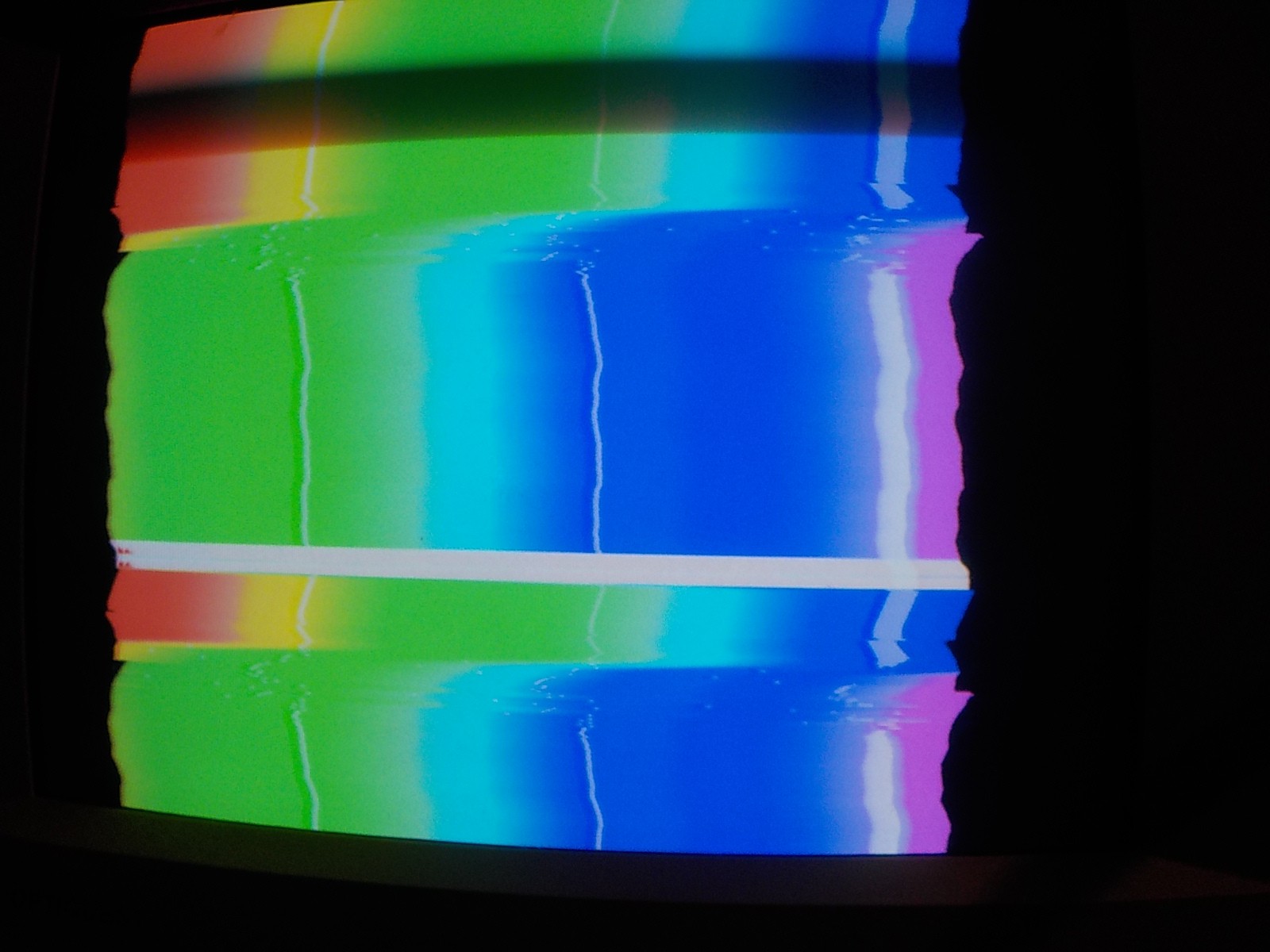
I wanted the video output to respond directly to the X Y position values. This circuit uses two comparator window circuits to check when the X, Y voltages match the voltages in the corrosponding ramp circuits. I was expecting this to produce a crosshair, but there was a problem: When moving the gun from side to side the crosshair was always a few inches to the right. This is because of some delay between the zapper's phototransistor detecting the raster beam and the signal making it all the way to the sample-and-hold triggers. It's only a problem with the horizontal position because the vertical is a much slower signal.
I solved this by adding a 555 in astable mode and resetting it on window circuit output. The 555 outputs several vertical lines that move left and right in unison. The point where the 555 is reset doesn't matter so long as it moves linearly with the light gun. position

The diodes at the final stage of this circuit allow the lines to be white without tying the R G B wires together and killing the rainbow effect.
The rainbow-phase-shift circuit built in the previous step gets distorted by the output of this circuit.
 Russell Kramer

Discussions
Become a Hackaday.io Member
Create an account to leave a comment. Already have an account? Log In.