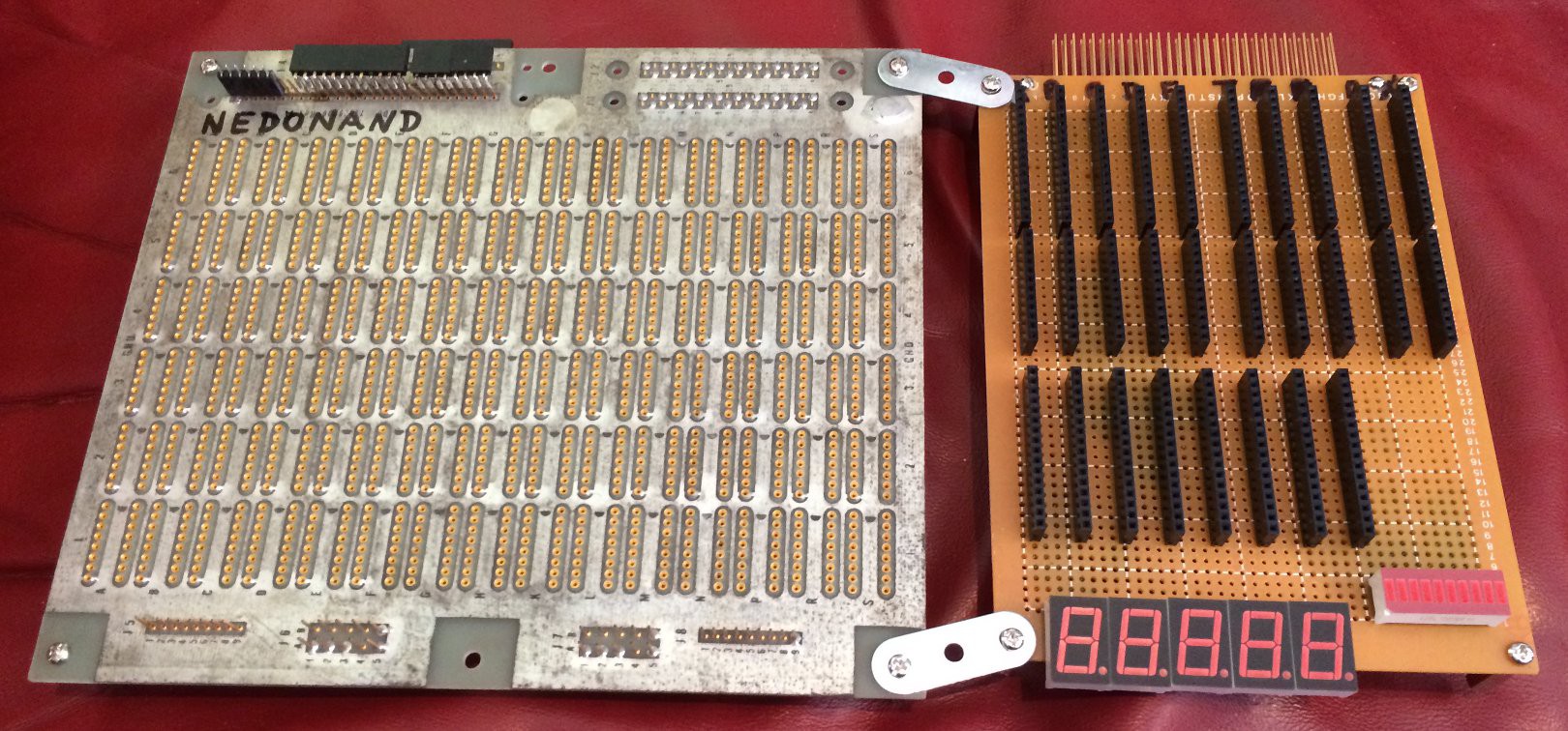
This is a motherboard to connect all parts of NEDONAND together. I decided to use "wire-wrap" technique, but because female header receptacles are relatively new and not exist in wire-wrapping form (with long terminals with square post) I used "side-kick" soldered board where I collect all header receptacles for NEDONAND boards (probably I will need another one to host everything):

On the top of a side-kick you can see sockets for registers A,B,C,D,E and T (temporary register) and some other things as multiplexers and demultiplexers. Five 7-segment indicators will show registers contents (directly without decoding) for registers A,B,C,D,E and 10-LED bar graph on the right to show content of register F plus 2 additional signals (as ALU usage flag for example). Golden header on the very top of a side-kick is an interface between wire-wrapped universe and soldered universe to make things easier...
 SHAOS
SHAOS
Discussions
Become a Hackaday.io Member
Create an account to leave a comment. Already have an account? Log In.
Daaamn I should get the #DYPLED ready so you don't have to deal with naked 7-segments displays. But I suppose you can buy #PICTIL before :-D
Are you sure? yes | no
No, it has to be bare NANDs - no microcontrollers, no even memory (at least in the beginning ; )
Are you sure? yes | no
ooops I forgot that little detail :-D
Are you sure? yes | no