-
Processing on the Pi - Gradation
02/24/2016 at 22:57 • 0 commentsDate: 2/4/2016
The projectors should be able to display anything, text, patterns, and maybe even photographic images. To do so the system would need to be able to convert color and greyscale images to 1-bit color. I found some sample code on the Processing forum that showed how to create a dithering effect.
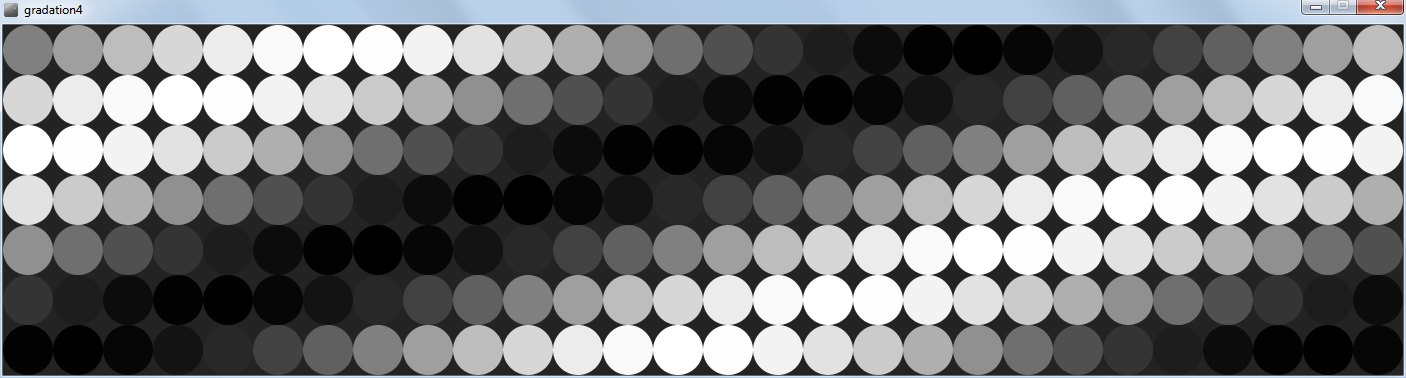
Below is an image of a gradation generated in Processing:
![]()
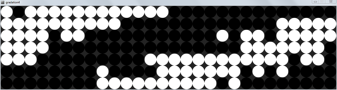
Here's the same gradation dithered by the code:
![]()
And, below is the code that creates an animated gradation, dithered for the flip-dot display:
// Gradation 4 // 1-bit image dithering // // For LinkSprite V3 and AlfaZeta flip-dot display // by Michael Shaub 2016 int dotSize = 50; //diameter of the dots - for preview PImage pix = createImage(28,7, RGB); //PImage to hold the actual size image int pixLength = pix.width*pix.height; //total amount of pixels boolean drawRow = false; //use to alternate drawing a row of dots or skipping float a = 0.0; float inc = TWO_PI/25.0; PImage pixOrig = createImage(28,7, RGB); //PImage to hold the actual size image void setup(){ size(1400,350); ellipseMode(CORNER); noStroke(); frameRate(3); //preset the PImage pix.loadPixels(); pixOrig.loadPixels(); for(int i=0; i<pixLength; i++){ pix.pixels[i] = color(0); //set each pixel to black pixOrig.pixels[i] = color(0); //set each pixel to black } pix.updatePixels(); pixOrig.updatePixels(); } void draw(){ background(35); //Draw a gradation pixOrig.loadPixels(); for(int j=0; j<7; j++){ for(int i=0; i<28; i++){ pixOrig.pixels[i+j*pix.width] = int(128+sin(a)*128.0); //set the fill color to a smooth gradation a = a + inc; } } pixOrig.updatePixels(); //do dithering biz here pix.loadPixels(); pixOrig.loadPixels(); for(int y=0; y<7; y++){ for(int x=0; x<28; x++){ color oldpixel = pixOrig.get(x, y); color newpixel = findClosestColor( color(brightness(oldpixel) + random(-100,100)) ); //the wider the range of randomness the "softer" the result. Lower is harder edge pix.pixels[x+y*pix.width] = newpixel; //copy colors from one image to the other } } pix.updatePixels(); pix.loadPixels(); for(int j=0; j<7; j++){ for(int i=0; i<28; i++){ fill( pix.pixels[i+j*pix.width] ); //read pixel values, set fill color to that ellipse(i*dotSize,j*dotSize,dotSize,dotSize); } } } color findClosestColor(color c) { color r; // Treshold function if (brightness(c) < 128) { r = color(0); } else { r = color(255); } return r; } -
Processing on the Pi - Snow
02/24/2016 at 04:19 • 0 commentsDate: 2/3/2016
Before I even received the flip-dot display I started working on some pixelated content. My first idea was to create a simple simulation of snowfall, creating some random dots at the top of the display, moving them down a row each frame, slightly shifting them left or right, and then collecting a few frames worth at the bottom of the screen. I quickly found out that I needed to keep space between the dots left and right and vertically, easily handled by skipping every other row when drawing new "snow flakes."
The canvas size is 28 pixels wide by 7 pixels tall, assuming that the images would span across the 4 7x7 pixel displays.
Processing sketch code below:
// Pixelated Snow V9 // // For LinkSprite V3 and AlfaZeta flip-dot display // by Michael Shaub 2016 int dotSize = 50; //diameter of the dots - for preview PImage pix = createImage(28,7, RGB); //PImage to hold the actual size image int pixLength = pix.width*pix.height; //total amount of pixels boolean drawRow = false; //use to alternate drawing a row of dots or skipping void setup(){ size(1400,350); ellipseMode(CORNER); noStroke(); frameRate(3); //preset the PImage pix.loadPixels(); for(int i=0; i<pixLength; i++){ pix.pixels[i] = color(0); //set each pixel to black } pix.updatePixels(); } void draw(){ background(35); //Copy each row of pixels down to the next row pix.loadPixels(); for(int j=6; j>0; j--){ //step through every row but the top one, in reverse int wind = round( random(-1,1) ); //set a value to blow the snow to the left, right, or none println(wind); for(int i=0; i<28; i++){ if(!drawRow && j==6){ //only if this is the bottom row and on a frame when the snow isn't drawn on the top row //skip drawing over the last row this frame }else{ //draw this frame int targetPix; //test boundaries for values if( (i+j*pix.width+wind) < 0){ targetPix = 0; }else{ if( (i+j*pix.width+wind) > 7*pix.width-1){ targetPix = (i+j*pix.width); }else{ targetPix = (i+j*pix.width+wind); } } pix.pixels[targetPix] = pix.pixels[i+(j-1)*pix.width]; //read pixel values, set fill color to the row above } } } //Draw the first row of pixels with random values //pix.loadPixels(); int lastRand = 0; for(int i=0; i<pix.width; i++){ int randValue = 0; if(drawRow){ randValue = round(random(.8))*255; //randomly black or white if(i>0 && lastRand==255){ randValue = 0; //never have 2 white dots in a row } } pix.pixels[i] = color(randValue); //set each pixel to black or white lastRand = randValue; } drawRow = !drawRow; //toggle the variable pix.updatePixels(); pix.loadPixels(); for(int j=0; j<7; j++){ for(int i=0; i<28; i++){ fill( pix.pixels[i+j*pix.width] ); //read pixel values, set fill color to that ellipse(i*dotSize,j*dotSize,dotSize,dotSize); } } } -
Processing on the Pi – Live Drawing
02/24/2016 at 04:02 • 0 commentsDate: 2/19/2016
I wanted to try something more interesting than test patterns on the flip dot display. I'd played a little bit with high speed to see how quickly the dots could respond which got me thinking about making something that ran in real-time. I wrote a program that showed a preview of the flip-dot display, allowed a mouse left-click to "draw" a white dot and a right-click to "erase" it back to black. I added a highlight around each dot location like a "mouse over" event to make it easier to see the mouse location.
Below is the code for the Live Drawing processing sketch:
// Live Draw sketch // For LinkSprite V3 and AlfaZeta flip-dot display // by Michael Shaub 2016 import processing.serial.*; // The serial port: Serial myPort; PImage pix = createImage(7, 7, RGB); int frameDelay = 50; //pause 400 ms between frames being sent to the board float dotSize = 0; void setup() { // List all the available serial ports: printArray(Serial.list()); // Open the port you are using at the rate you want: myPort = new Serial(this, Serial.list()[0], 57600); size(500,500); dotSize = height/7.0; pix.loadPixels(); for (int i = 0; i < pix.pixels.length; i++) { pix.pixels[i] = color(0); } pix.updatePixels(); noStroke(); ellipseMode(CORNER); } void draw(){ background(0); boolean dot = false; pix.loadPixels(); //bitshift values from array int row1 = 0; int row2 = 0; int row3 = 0; int row4 = 0; int row5 = 0; int row6 = 0; int row7 = 0; for (int y = 0; y < pix.height; y++) { for (int x = 0; x < pix.width; x++) { stroke(64); strokeWeight(1); noFill(); ellipse(x*dotSize,y*dotSize,dotSize,dotSize); noStroke(); if( pix.pixels[x+y*pix.width] == color(255) ){ //draw on screen fill(255); ellipse(x*dotSize,y*dotSize,dotSize,dotSize); } if(round(mouseX/dotSize-.5)==x && round(mouseY/dotSize-.5)==y){ stroke(128); strokeWeight(4); noFill(); ellipse(x*dotSize,y*dotSize,dotSize,dotSize); noStroke(); if (mousePressed && (mouseButton == LEFT)) { pix.pixels[x+y*pix.width] = color(255); } if (mousePressed && (mouseButton == RIGHT)) { pix.pixels[x+y*pix.width] = color(0); } } } } pix.updatePixels(); pix.loadPixels(); for (int y = 0; y < pix.height; y++) { for (int x = 0; x < pix.width; x++) { if( pix.pixels[x+y*pix.width] == color(255) ){ //prep for fipDot message int b = 1 << x; //bitshift the value the number of positions equal to the digit switch(y+1){ case 1: row1 = row1 | b; //bitwise OR addition of the "b" value to the existing "row3" value break; case 2: row2 = row2 | b; //bitwise OR addition of the "b" value to the existing "row3" value break; case 3: row3 = row3 | b; //bitwise OR addition of the "b" value to the existing "row3" value break; case 4: row4 = row4 | b; //bitwise OR addition of the "b" value to the existing "row3" value break; case 5: row5 = row5 | b; //bitwise OR addition of the "b" value to the existing "row3" value break; case 6: row6 = row6 | b; //bitwise OR addition of the "b" value to the existing "row3" value break; case 7: row7 = row7 | b; //bitwise OR addition of the "b" value to the existing "row3" value break; } } } } pix.updatePixels(); int test_2[]= {0x80, 0x87, 0xFF, row1, row2, row3, row4, row5, row6, row7, 0x8F}; for(int i=0; i<test_2.length; i++){ myPort.write(test_2[i]); } delay (frameDelay); } -
Processing on the Pi - Networking
02/24/2016 at 03:47 • 0 commentsDate: 2/6/2016
For the Projectors to synchronize over WiFi I needed them to be able to communicate via the Processing sketches. Since I've used OSCp5 library in the past, that was an obvious thing to try. The library runs on the Raspberry Pi but not as I'd expected. All the sketches that use the loopback or local host address to test sending and receiving on the same device worked fine. But, when I tried to have another computer contact the Pi over the network it never worked properly. I asked for help on the Processing Forum here but didn't get help fast enough for this project.
So, Plan B.
I found some example sketches on the Processing website in an article called Network Tutorial. In that series there's an example called Shared Drawing Canvas that I decided to try and it worked! Even though the Pi wouldn't report its IP address properly, when I specified the address it worked just fine. The code is shown below:
// by Alexander R. Galloway // from https://processing.org/tutorials/network/ // 2A: Shared drawing canvas (Server) - see Client Below import processing.net.*; Server s; Client c; String input; int data[]; void setup() { size(450, 255); background(204); stroke(0); frameRate(5); // Slow it down a little s = new Server(this, 12345); // Start a simple server on a port } void draw() { if (mousePressed == true) { // Draw our line stroke(255); line(pmouseX, pmouseY, mouseX, mouseY); // Send mouse coords to other person s.write(pmouseX + " " + pmouseY + " " + mouseX + " " + mouseY + "\n"); } // Receive data from client c = s.available(); if (c != null) { input = c.readString(); input = input.substring(0, input.indexOf("\n")); // Only up to the newline data = int(split(input, ' ')); // Split values into an array // Draw line using received coords stroke(0); line(data[0], data[1], data[2], data[3]); } } //---------------------(client commented out below)------------------------------// /* // 2B: Shared drawing canvas (Client) import processing.net.*; Client c; String input; int data[]; void setup() { size(450, 255); background(204); stroke(0); frameRate(5); // Slow it down a little // Connect to the server’s IP address and port c = new Client(this, "192.168.86.106", 12345); // Replace with your server’s IP and port } void draw() { if (mousePressed == true) { // Draw our line stroke(255); line(pmouseX, pmouseY, mouseX, mouseY); // Send mouse coords to other person c.write(pmouseX + " " + pmouseY + " " + mouseX + " " + mouseY + "\n"); } // Receive data from server if (c.available() > 0) { input = c.readString(); input = input.substring(0,input.indexOf("\n")); // Only up to the newline data = int(split(input, ' ')); // Split values into an array // Draw line using received coords stroke(0); line(data[0], data[1], data[2], data[3]); } } */ -
Processing on the Pi – RS485
02/24/2016 at 03:27 • 0 commentsDate: 2/19/2016
For the project to work I had to get the Raspberry Pi to do the same thing the Arduino. The LinkSprite shield does work with the Raspberry Pi V2 (and I'm assuming other models with 40 pin GPIO pins) even though it only has 26 pins. Just align the 1st pin of each and leave the other 14 unused.
(insert link to GPIO serial settings)
Once I'd opened up the serial connection to be available for Processing I just copied and pasted the code from the Arduino IDE to Processing. The Arduino Serial.begin(57600); becomes myPort = new Serial(this, Serial.list()[0], 57600); to select the first (only) serial port available. To send a command, instead of Serial.write( message ); Processing will need it to be myPort.write( message );
Below is my working Processing code, using the LinkSprite shield.
// Serial example by Tom Igoe // // Adapted for LinkSprite V3 and AlfaZeta flip-dot display // by Michael Shaub 2016 import processing.serial.*; // The serial port: Serial myPort; int delay_tr = 1000; byte test_allWhite[]= {byte(0x80), byte(0x87), byte(0xFF), byte(0x7F), byte(0x7F), byte(0x7F), byte(0x7F), byte(0x7F), byte(0x7F), byte(0x7F), byte(0x8F)}; byte test_allBlack[]= {byte(0x80), byte(0x87), byte(0xFF), byte(0x00), byte(0x00), byte(0x00), byte(0x00), byte(0x00), byte(0x00), byte(0x00), byte(0x8F)}; int frameDelay = 50; //pause 400 ms between frames being sent to the board int counter = 0; int rowCounter = 0; int row1 = 0; //hold variable for row1 int row2 = 0; //hold variable for row2 int row3 = 0; //hold variable for row3 int row4 = 0; //hold variable for row4 int row5 = 0; //hold variable for row5 int row6 = 0; //hold variable for row6 int row7 = 0; //hold variable for row7 int rowArray[ ] = {0,0,0,0,0,0,0}; void setup(){ // List all the available serial ports: printArray(Serial.list()); // Open the port you are using at the rate you want: myPort = new Serial(this, Serial.list()[0], 57600); // Send a capital A out the serial port: //myPort.write(65); } void draw(){ //count rows and frames if(counter > 7){ counter = 0; rowCounter++; } if(rowCounter > 7) rowCounter = 0; for(int j=0; j<7; j++){ //set values to match counter, should flip dots one by one across if(j == counter){ rowArray[j] = 1; //set to 1 }else{ rowArray[j] = 0; //reset value to 0 } } //bitshift values from array row1 = 0; row2 = 0; row3 = 0; row4 = 0; row5 = 0; row6 = 0; row7 = 0; for(int i=0; i<rowArray.length; i++){ int a = rowArray[i]; int b = a << i; //bitshift the value the number of positions equal to the digit switch(rowCounter){ case 1: row1 = row1 | b; //bitwise OR addition of the "b" value to the existing "row3" value break; case 2: row2 = row2 | b; //bitwise OR addition of the "b" value to the existing "row3" value break; case 3: row3 = row3 | b; //bitwise OR addition of the "b" value to the existing "row3" value break; case 4: row4 = row4 | b; //bitwise OR addition of the "b" value to the existing "row3" value break; case 5: row5 = row5 | b; //bitwise OR addition of the "b" value to the existing "row3" value break; case 6: row6 = row6 | b; //bitwise OR addition of the "b" value to the existing "row3" value break; case 7: row7 = row7 | b; //bitwise OR addition of the "b" value to the existing "row3" value break; } } int test_2[]= {0x80, 0x87, 0xFF, row1, row2, row3, row4, row5, row6, row7, 0x8F}; //int test_2[]= {0x80, 0x87, 0xFF, 0, counter, 0, 0, 0, 0, 0, 0x8F}; for(int i=0; i<test_2.length; i++){ myPort.write(test_2[i]); } //myPort.write(60); //println("Dark"); counter++; delay (frameDelay); } -
Housing Design Process
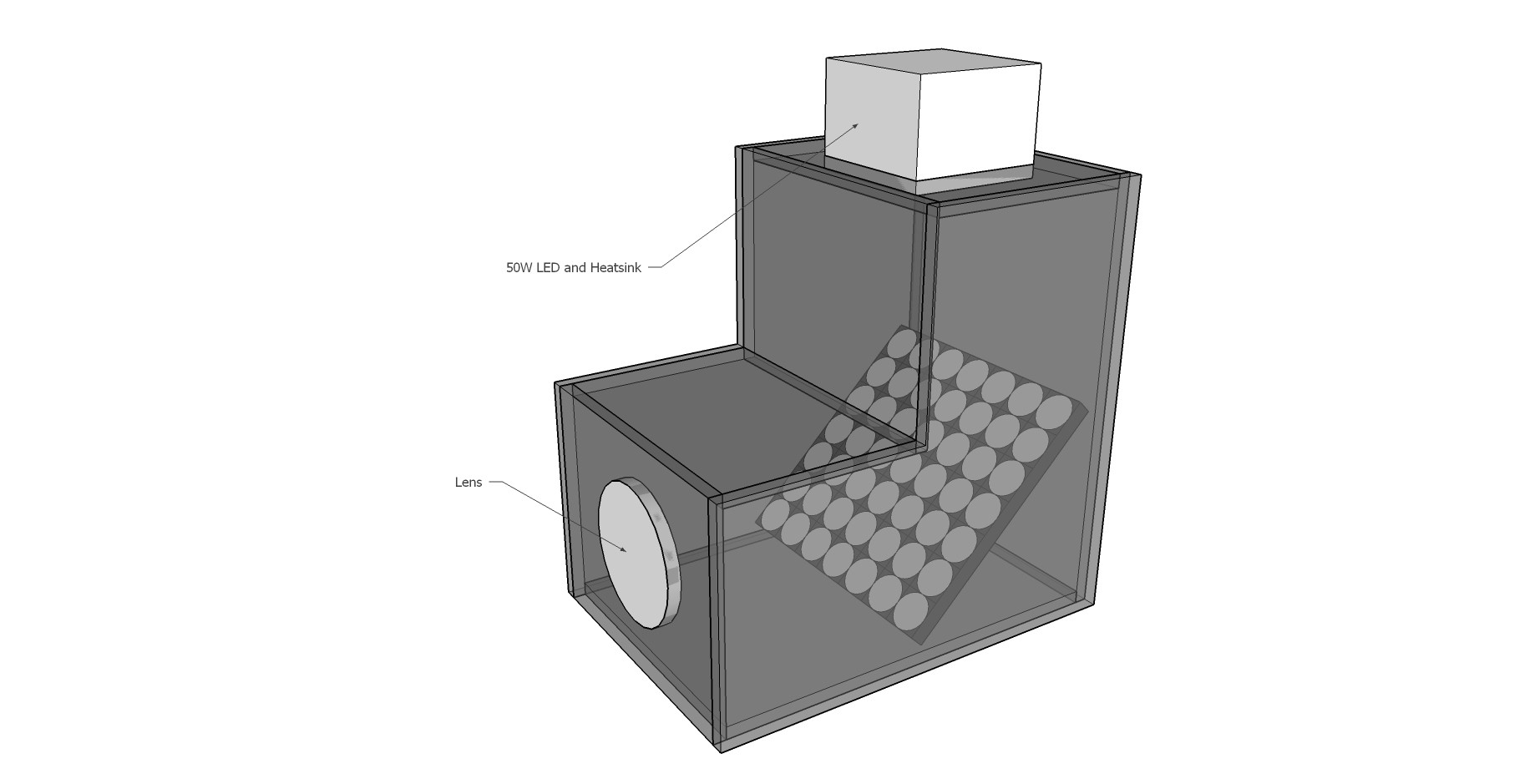
02/22/2016 at 04:31 • 0 comments![]()
Above is an initial sketch of a top mounted LED light source, 45 degree angle flip-dot mirror display, and a lens. Tests with a 50W LED were not successful, nor was use of a lens (at least one I had on hand) after the light hit the flip-dot display. It worked much better to have a focused beam bounce off the dots, putting the lens between the LED and the display.
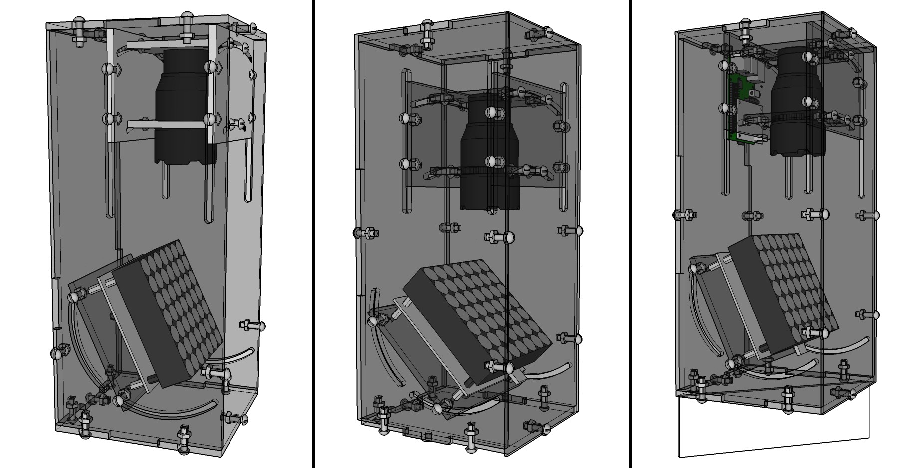
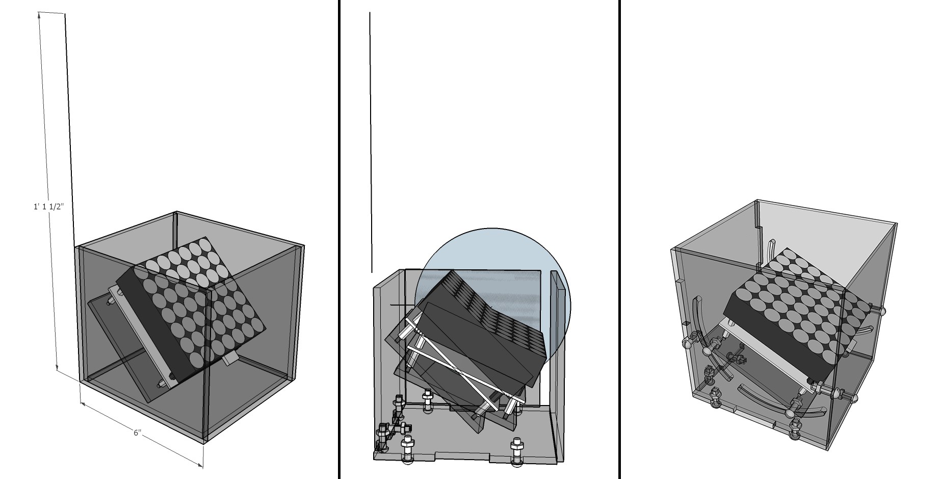
![]() Above are 3 steps of working out how tight the acrylic housing could be to the display, while still allowing for adjustment of its angle.
Above are 3 steps of working out how tight the acrylic housing could be to the display, while still allowing for adjustment of its angle.![]()
3 more stages of refinement of the model, adding the LED light source at a distance based on tests with the actual display and LED flashlight at a few focal lengths. These have an angle adjustment for the LED, centered on the display, because I noticed that the flip-dots don't lay completely flat and shifted the projected image off to one side.
![]()
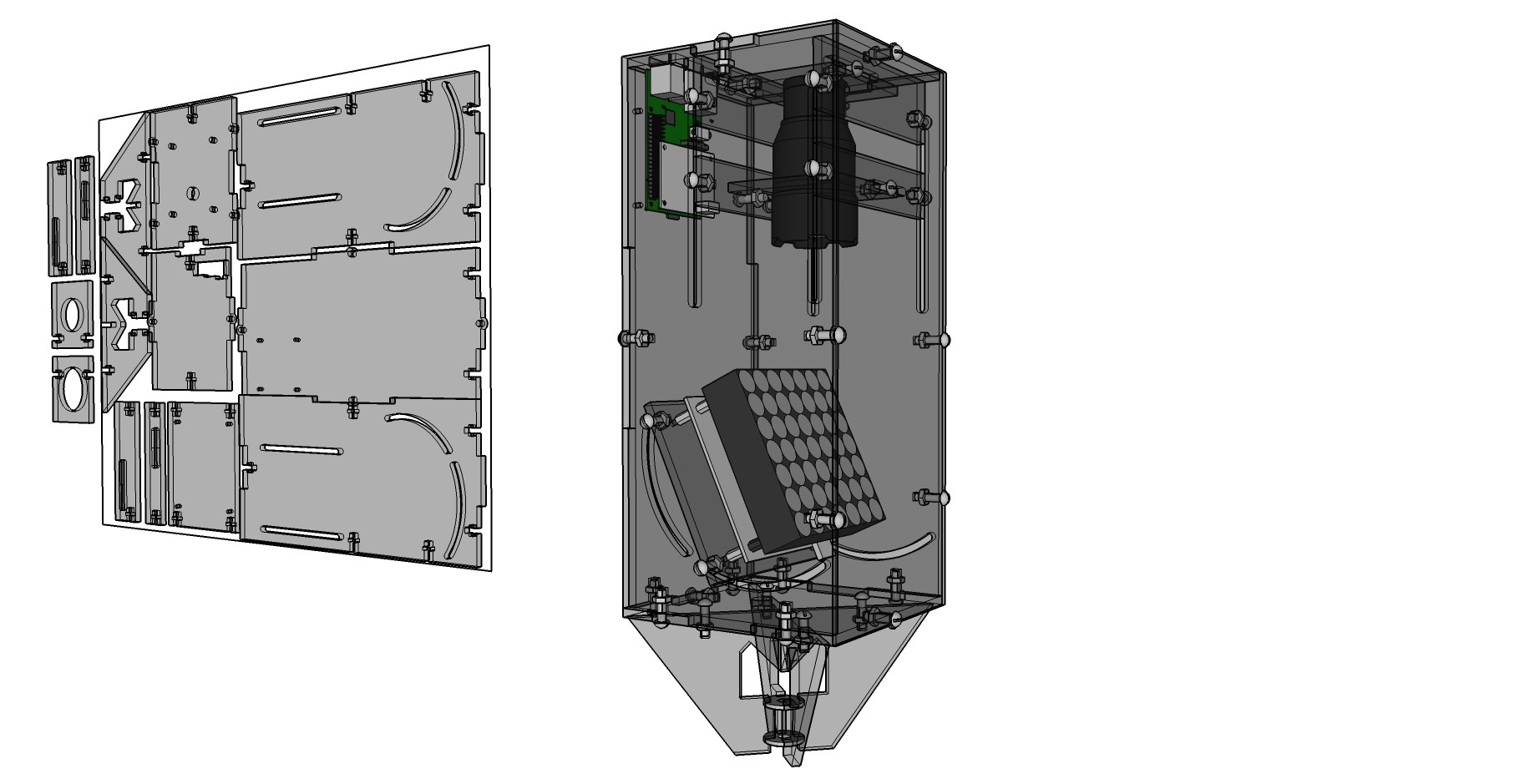
Above is the final model of the case, including a connection for a cymbal stand from a drum kit on the bottom. This version has a new vertical adjustment for the flashlight since it focuses by sliding the lens in and out and I'd forgotten to include that previously. To the left is a layout of all the components nested into an 18x24 sheet of acrylic (the size I could easily find at a local hardware store) with a few left over to add on another sheet.
-
Testing the Flip-Dot Display - Success
02/21/2016 at 23:32 • 0 commentsDate: 2/14/2016
I tried alterations to the sample code until I got the flip-dot display to act more predictably.
Below is my revised code for the display with a little extra to automatically count up columns and rows:
/* Simple Serial ECHO script : Written by ScottC 04/07/2012 */ /* Stage 2 : Delimiters */ /* Adapted for LinkSprite V3 and AlfaZeta flip-dot display */ /* by Michael Shaub 2016 */
/* Use a variable called byteRead to temporarily store the data coming from the computer */ //refresh all panels //0x80 0x82 0x8F int frameDelay = 250; //pause 400 ms between frames being sent to the board int counter = 0; int rowCounter = 0; int row1 = 0; //hold variable for row1 int row2 = 0; //hold variable for row2 int row3 = 0; //hold variable for row3 int row4 = 0; //hold variable for row4 int row5 = 0; //hold variable for row5 int row6 = 0; //hold variable for row6 int row7 = 0; //hold variable for row7 String rowString = "B1101010"; int rowArray[ ] = {0,0,0,0,0,0,0}; void setup() { // Turn the Serial Protocol ON Serial.begin(57600); } void loop() { //header, Command, Address, Data, End Character (0xFF address = ALL BOARDS) if(counter > 7){ counter = 0; rowCounter++; } if(rowCounter > 7) rowCounter = 0; byte test_allWhite[]= {128, 136, 255, 0x7F, 0x7F, 0x7F, 0x7F, 0x7F, 0x7F, 0x7F, 0x8F}; byte test_allBlack[]= {128, 136, 255, 0x00, 0x00, 0x00, 0x00, 0x00, 0x00, 0x00, 0x8F}; byte refresh_all[]= {0x80, 0x82, 0x8F}; //Serial.write(test_1, 116); //Serial.write(test_allWhite, 116); //Serial.write(test_1, 116); //Serial.write(refresh_all, 116); //row3 = byte(B1111010); for(int j=0; j<8; j++){ //set values to match counter, should flip dots one by one across if(j == counter){ rowArray[j] = 1; //set to 1 }else{ rowArray[j] = 0; //reset value to 0 } } /* if(counter == 1){ rowArray[0] = 1; } if(counter == 2){ rowArray[0] = 0; rowArray[1] = 1; } if(counter == 3){ rowArray[1] = 0; rowArray[2] = 1; } */ row1 = 0; row2 = 0; row3 = 0; row4 = 0; row5 = 0; row6 = 0; row7 = 0; for(int i=0; i<8; i++){ int a = rowArray[i]; int b = a << i; //bitshift the value the number of positions equal to the digit switch(rowCounter){ case 1: row1 = row1 | b; //bitwise OR addition of the "b" value to the existing "row3" value break; case 2: row2 = row2 | b; //bitwise OR addition of the "b" value to the existing "row3" value break; case 3: row3 = row3 | b; //bitwise OR addition of the "b" value to the existing "row3" value break; case 4: row4 = row4 | b; //bitwise OR addition of the "b" value to the existing "row3" value break; case 5: row5 = row5 | b; //bitwise OR addition of the "b" value to the existing "row3" value break; case 6: row6 = row6 | b; //bitwise OR addition of the "b" value to the existing "row3" value break; case 7: row7 = row7 | b; //bitwise OR addition of the "b" value to the existing "row3" value break; } } byte test_2[]= {0x80, 0x87, 0xFF, row1, row2, row3, row4, row5, row6, row7, 0x8F}; Serial.write(test_2, 116); //Serial.write(test_1, 116); //Serial.write(refresh_all, 116); delay(frameDelay); // wait for a second counter++; /* row1 = counter; row2 = counter; row3 = counter; row4 = counter; row5 = counter; row6 = counter; row7 = counter; */ } -
Testing the Flip-Dot Display
02/21/2016 at 21:07 • 0 commentsDate: 2/12/2016
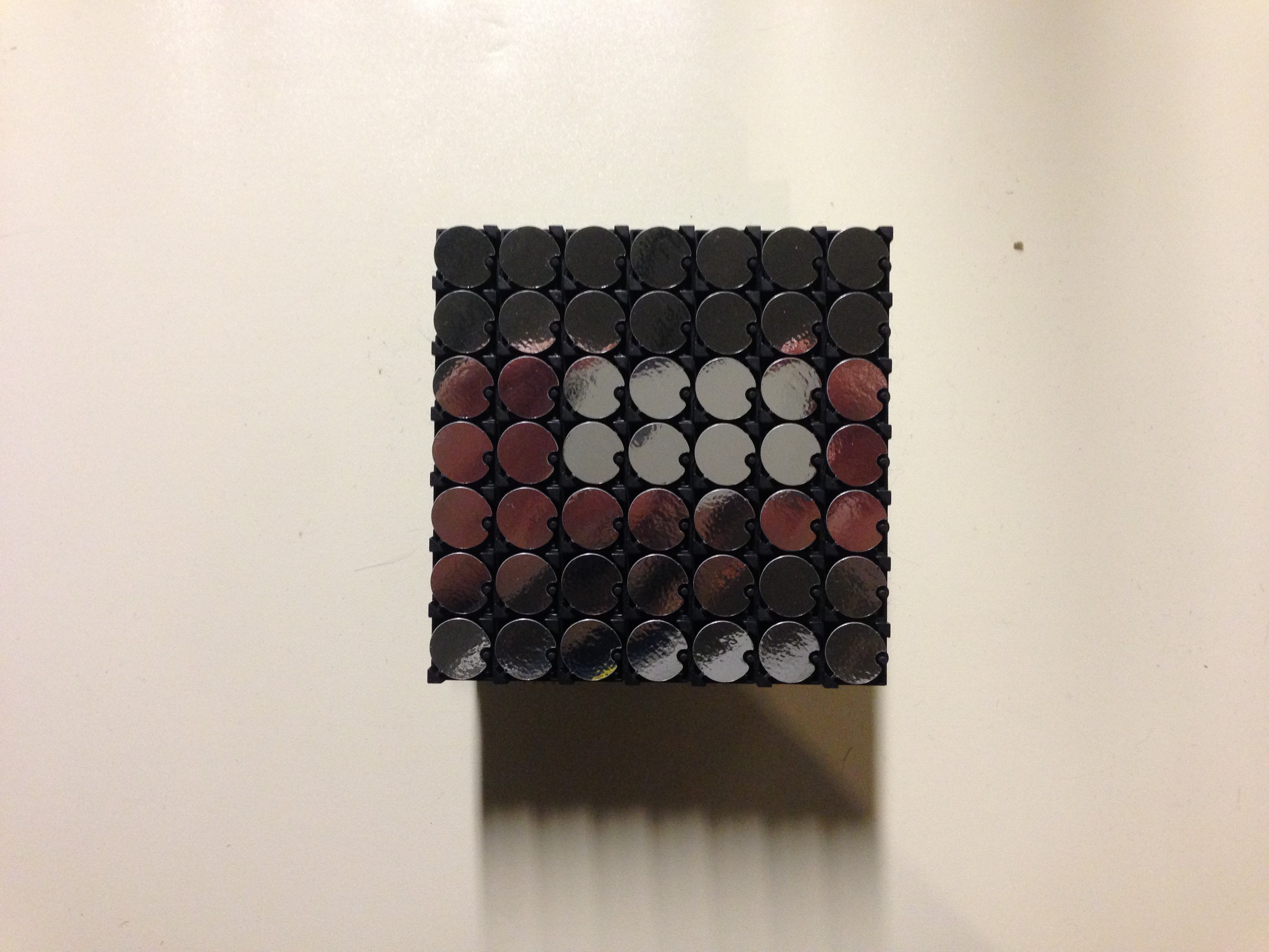
I used the sample code from AlfaZeta with the flip-dot and it didn't work properly. The note in the sample code "// panel's speed setting: 1-OFF 2-ON 3 - ON" apparently meant that I should turn on the Dip-switches 3 & 4 to get anything to work from the Arduino commands.
![]()
With the Dip-switches set properly, the panel finally began flipping. It wasn't doing what I had expected, but exciting to see it do something.
-
Unboxing the Flip-Dot Display
02/21/2016 at 20:21 • 0 commentsDate: 2/11/2016
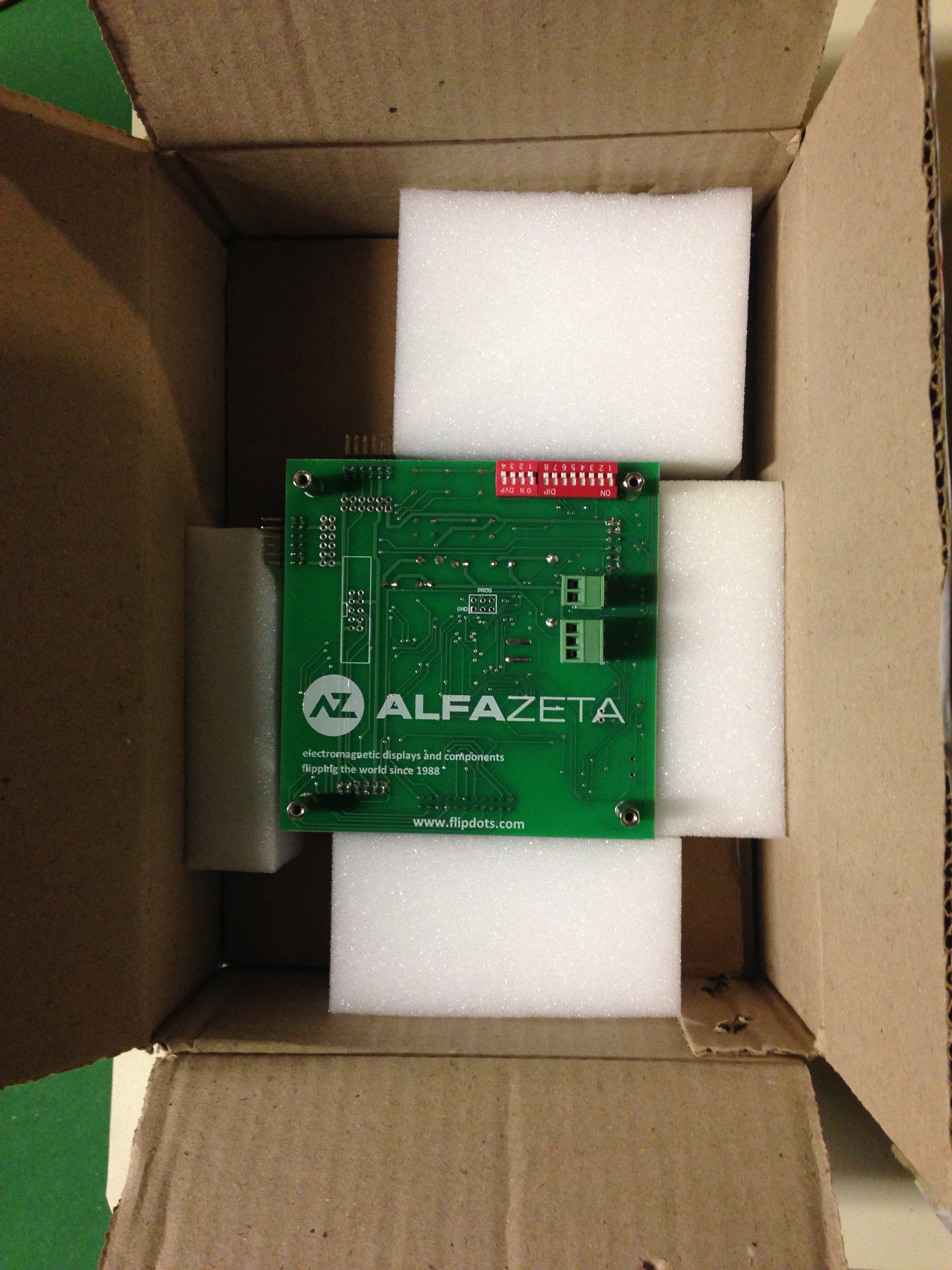
I finally received my long-awaited flip-dot display from AlfaZeta, shipped from Poland.
![]()
![]()
Even though I plan to use a Raspberry Pi to control the display, I used an Arduino with a SparkFun RS-485 Transceiver Breakout Board (BOB-10124) for testing. AlfaZeta was kind enough to send me some sample code for the Arduino, so that was a pretty obvious choice to start.
Arduino Code Sample from AlfaZeta:
// 0x80 beginning
//___________________
// 0x81 - 112 bytes / no refresh / C+3E
// 0x82 - refresh
// 0x83 - 28 bytes of data / refresh / 2C
// 0x84 - 28 bytes of data / no refresh / 2C
// 0x85 - 56 bytes of data / refresh / C+E
// 0x86 - 56 bytes of data / no refresh / C+E
// ---------------------------------------
// address or 0xFF for all
// data ... 1 to nuber of data bytes
// 0x8F end

// panel's speed setting: 1-OFF 2-ON 3 - ON
// panel address : 1 (8 pos dip switch: 1:on 2 -8: off)

// I was using RS485 Breakout and Duemilanova connected in the following way:
// [Panel]  [RS485]  [Arduino]
// 485+       A
// 485-       B
//          3-5V    5V
//          RX-I    TX
//          TX-O    Not connected
//           RTS    5V
//           GND    GND

// these are blank transmissions for various controller configurations: CE - one controller + one extension, 2C - two controllers (the most popular), C3E - one controller + threee extensions
// you can use them by putting data bytes

byte sign_CE[]= {0x80, 0x85, 0x01, 0x00, 0x00, 0x00, 0x00, 0x00, 0x00, 0x00, 0x00, 0x00, 0x00, 0x00, 0x00, 0x00, 0x00, 0x00, 0x00, 0x00, 0x00, 0x00, 0x00, 0x00, 0x00, 0x00, 0x00, 0x00, 0x00, 0x00, 0x00,
                  0x00, 0x00, 0x00, 0x00, 0x00, 0x00, 0x00, 0x00, 0x00, 0x00, 0x00, 0x00, 0x00, 0x00, 0x00, 0x00, 0x00, 0x00, 0x00, 0x00, 0x00, 0x00, 0x00, 0x00, 0x00, 0x00, 0x00, 0x00, 0x8F};

byte sign_2C[]= {0x80, 0x85, 0x01, 0x00, 0x00, 0x00, 0x00, 0x00, 0x00, 0x00, 0x00, 0x00, 0x00, 0x00, 0x00, 0x00, 0x00, 0x00, 0x00, 0x00, 0x00, 0x00, 0x00, 0x00, 0x00, 0x00, 0x00, 0x00, 0x00, 0x00, 0x00, 0x8F};

byte sign_C3E[]= {0x80, 0x85, 0x01, 0x00, 0x00, 0x00, 0x00, 0x00, 0x00, 0x00, 0x00, 0x00, 0x00, 0x00, 0x00, 0x00, 0x00, 0x00, 0x00, 0x00, 0x00, 0x00, 0x00, 0x00, 0x00, 0x00, 0x00, 0x00, 0x00, 0x00, 0x00,
                  0x00, 0x00, 0x00, 0x00, 0x00, 0x00, 0x00, 0x00, 0x00, 0x00, 0x00, 0x00, 0x00, 0x00, 0x00, 0x00, 0x00, 0x00, 0x00, 0x00, 0x00, 0x00, 0x00, 0x00, 0x00, 0x00, 0x00, 0x00, 0x00, 0x00, 0x00,
                  0x00, 0x00, 0x00, 0x00, 0x00, 0x00, 0x00, 0x00, 0x00, 0x00, 0x00, 0x00, 0x00, 0x00, 0x00, 0x00, 0x00, 0x00, 0x00, 0x00, 0x00, 0x00, 0x00, 0x00, 0x00, 0x00, 0x00, 0x00, 0x00, 0x00, 0x00,
                  0x00, 0x00, 0x00, 0x00, 0x00, 0x00, 0x00, 0x00, 0x00, 0x00, 0x00, 0x00, 0x00, 0x00, 0x00, 0x00, 0x00, 0x00, 0x00, 0x00, 0x00, 0x00, 0x8F};

// dark / bright transmissions for configurations above
byte all_bright_CE[]= {0x80, 0x85, 0x01, 0x7F, 0x7F, 0x7F, 0x7F, 0x7F, 0x7F, 0x7F, 0x7F, 0x7F, 0x7F, 0x7F, 0x7F, 0x7F, 0x7F, 0x7F, 0x7F, 0x7F, 0x7F, 0x7F, 0x7F, 0x7F, 0x7F, 0x7F, 0x7F, 0x7F, 0x7F, 0x7F, 0x7F,
                                         0x7F, 0x7F, 0x7F, 0x7F, 0x7F, 0x7F, 0x7F, 0x7F, 0x7F, 0x7F, 0x7F, 0x7F, 0x7F, 0x7F, 0x7F, 0x7F, 0x7F, 0x7F, 0x7F, 0x7F, 0x7F, 0x7F, 0x7F, 0x7F, 0x7F, 0x7F, 0x7F, 0x7F, 0x8F};

byte all_bright_2C[]= {0x80, 0x85, 0x01, 0x7F, 0x7F, 0x7F, 0x7F, 0x7F, 0x7F, 0x7F, 0x7F, 0x7F, 0x7F, 0x7F, 0x7F, 0x7F, 0x7F, 0x7F, 0x7F, 0x7F, 0x7F, 0x7F, 0x7F, 0x7F, 0x7F, 0x7F, 0x7F, 0x7F, 0x7F, 0x7F, 0x7F, 0x8F};

byte all_bright_C3E[]= {0x80, 0x85, 0x01, 0x7F, 0x7F, 0x7F, 0x7F, 0x7F, 0x7F, 0x7F, 0x7F, 0x7F, 0x7F, 0x7F, 0x7F, 0x7F, 0x7F, 0x7F, 0x7F, 0x7F, 0x7F, 0x7F, 0x7F, 0x7F, 0x7F, 0x7F, 0x7F, 0x7F, 0x7F, 0x7F, 0x7F,
                                          0x7F, 0x7F, 0x7F, 0x7F, 0x7F, 0x7F, 0x7F, 0x7F, 0x7F, 0x7F, 0x7F, 0x7F, 0x7F, 0x7F, 0x7F, 0x7F, 0x7F, 0x7F, 0x7F, 0x7F, 0x7F, 0x7F, 0x7F, 0x7F, 0x7F, 0x7F, 0x7F, 0x7F,
                                          0x7F, 0x7F, 0x7F, 0x7F, 0x7F, 0x7F, 0x7F, 0x7F, 0x7F, 0x7F, 0x7F, 0x7F, 0x7F, 0x7F, 0x7F, 0x7F, 0x7F, 0x7F, 0x7F, 0x7F, 0x7F, 0x7F, 0x7F, 0x7F, 0x7F, 0x7F, 0x7F, 0x7F,
                                          0x7F, 0x7F, 0x7F, 0x7F, 0x7F, 0x7F, 0x7F, 0x7F, 0x7F, 0x7F, 0x7F, 0x7F, 0x7F, 0x7F, 0x7F, 0x7F, 0x7F, 0x7F, 0x7F, 0x7F, 0x7F, 0x7F, 0x7F, 0x7F, 0x7F, 0x7F, 0x7F, 0x7F, 0x8F};


byte all_dark_CE[]= {0x80, 0x85, 0x01, 0x00, 0x00, 0x00, 0x00, 0x00, 0x00, 0x00, 0x00, 0x00, 0x00, 0x00, 0x00, 0x00, 0x00, 0x00, 0x00, 0x00, 0x00, 0x00, 0x00, 0x00, 0x00, 0x00, 0x00, 0x00, 0x00, 0x00, 0x00,
                  0x00, 0x00, 0x00, 0x00, 0x00, 0x00, 0x00, 0x00, 0x00, 0x00, 0x00, 0x00, 0x00, 0x00, 0x00, 0x00, 0x00, 0x00, 0x00, 0x00, 0x00, 0x00, 0x00, 0x00, 0x00, 0x00, 0x00, 0x00, 0x8F};

byte all_dark_2C[]= {0x80, 0x85, 0x01, 0x00, 0x00, 0x00, 0x00, 0x00, 0x00, 0x00, 0x00, 0x00, 0x00, 0x00, 0x00, 0x00, 0x00, 0x00, 0x00, 0x00, 0x00, 0x00, 0x00, 0x00, 0x00, 0x00, 0x00, 0x00, 0x00, 0x00, 0x00, 0x8F};

byte all_dark_C3E[]= {0x80, 0x85, 0x01, 0x00, 0x00, 0x00, 0x00, 0x00, 0x00, 0x00, 0x00, 0x00, 0x00, 0x00, 0x00, 0x00, 0x00, 0x00, 0x00, 0x00, 0x00, 0x00, 0x00, 0x00, 0x00, 0x00, 0x00, 0x00, 0x00, 0x00, 0x00,
                  0x00, 0x00, 0x00, 0x00, 0x00, 0x00, 0x00, 0x00, 0x00, 0x00, 0x00, 0x00, 0x00, 0x00, 0x00, 0x00, 0x00, 0x00, 0x00, 0x00, 0x00, 0x00, 0x00, 0x00, 0x00, 0x00, 0x00, 0x00, 0x00, 0x00, 0x00,
                  0x00, 0x00, 0x00, 0x00, 0x00, 0x00, 0x00, 0x00, 0x00, 0x00, 0x00, 0x00, 0x00, 0x00, 0x00, 0x00, 0x00, 0x00, 0x00, 0x00, 0x00, 0x00, 0x00, 0x00, 0x00, 0x00, 0x00, 0x00, 0x00, 0x00, 0x00,
                  0x00, 0x00, 0x00, 0x00, 0x00, 0x00, 0x00, 0x00, 0x00, 0x00, 0x00, 0x00, 0x00, 0x00, 0x00, 0x00, 0x00, 0x00, 0x00, 0x00, 0x00, 0x00, 0x8F};


void setup() {
  Serial.begin(57600);
}

void loop() {

// delay between transmissions: 200 ms is a safe value for CE configuration, you can play with this. For 2C you should be able to ge down to 100 ms

  int delay_tr = 200;

// CE

//  Serial.write(all_dark_CE, 60);
//  delay (delay_tr);
//  Serial.write(all_bright_CE, 60);
//   delay (delay_tr);


// 2C

  Serial.write(all_dark_2C, 32);
   delay (200);
  Serial.write(all_bright_2C, 32);
   delay (200);

// C3E

// Serial.write(all_dark_C3E, 116);
//   delay (200);
//  Serial.write(all_dark_C3E, 116);
//   delay (200);

}
Networked Low Resolution DMD Projectors
WiFi networked electro-mechanical 7x7 pixel flip-dot displays as giant DMDs (Digital Micromirror Devices) for low resolution projection
 Above are 3 steps of working out how tight the acrylic housing could be to the display, while still allowing for adjustment of its angle.