-
1Step 1
Not a step-by-step start to finish guide to recreate an exact replica. Just a bunch of interesting chunks. Re-usable as 'inspiration' for other projects that contain similar parts.
-
2Step 2
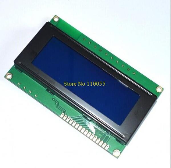
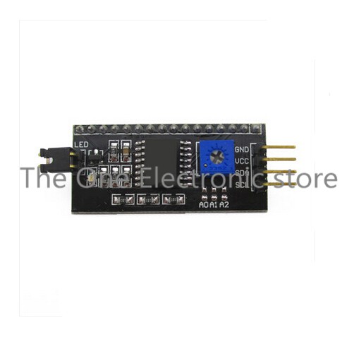
LCD display
The LCD display is a generic 4 line 20 character module. It exposes a set of ~16 digital connections. Because the controller has a limited I/O count, the LCD module is connected through the I2C bus. The I2C bus to LCD2004 combination is quite common, and matching controllers can be found.
In order to correctly drive the LCD display this module is powered by 5V. The I2C bus signals are correctly interpreted as the 3.3V level is seen as logic high.
![LCD 2004]()
![I2C LCD interface]()
see ManualPage.cpp (and others)
-
3Step 3
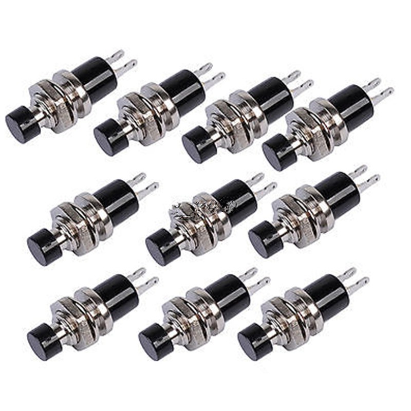
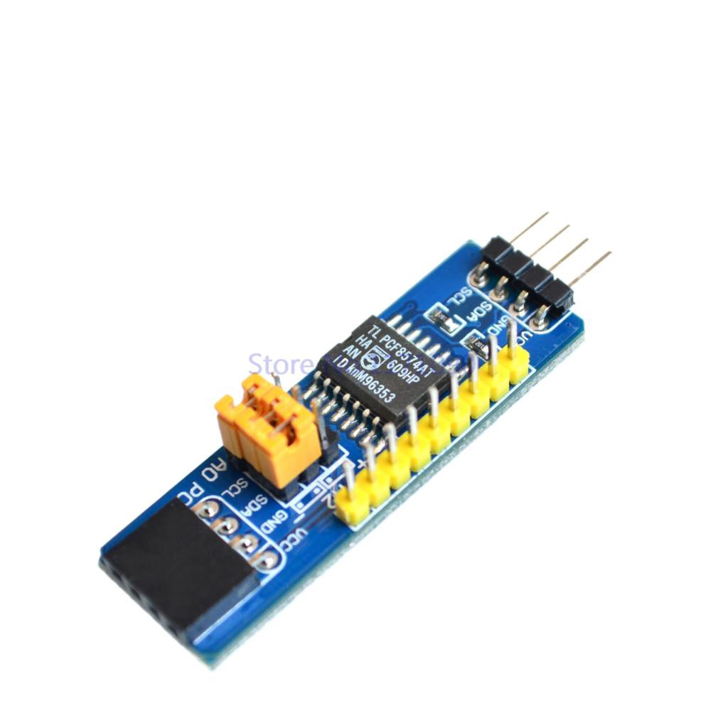
Menu push buttons
Because the controller has a limited I/O count, the push buttons are connected through the I2C bus. The PCF8574 digital I/O expander has built-in pull-up resistors and because only 8 buttons are required these are connected one-on-one on each of the available input pins. In order to be consistent, and allow common I2C bus wiring, the I/O extender is powered by 5V.
Skimping on a de-bouncing filter is possible, the controller can do this in software.
![Menu push buttons]()
![I2C digital I/O extender]()
-
4Step 4
Stepper motor control
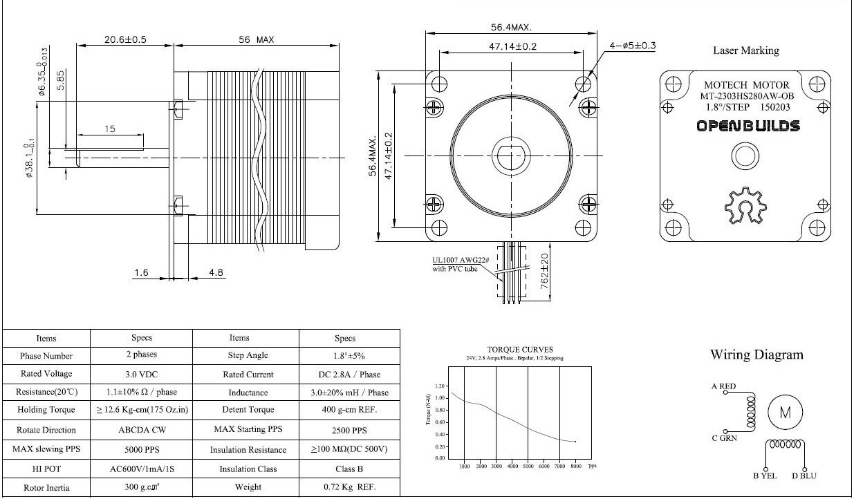
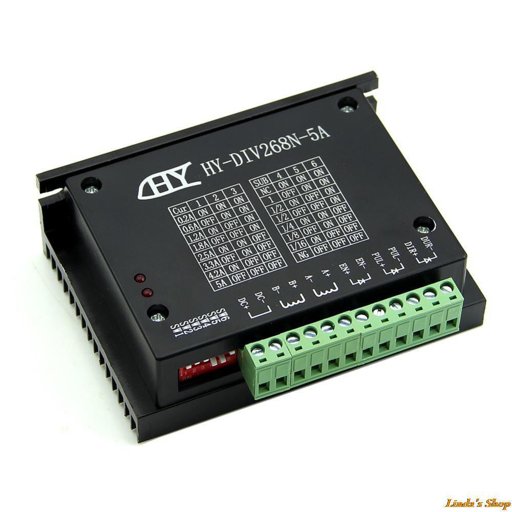
The stepper motor, a NEMA 23 type, is strong and equally power hungry. A good stepper motor driver controls the current through the motor. The chosen stepper motor controller might be a little over-dimensioned but can be easily limited using discrete switches.
The stepper motor:- NEMA 23
- Shaft Size: 1/4"
- Torque: 175 oz-in
- Step Angle: 1.8 deg/step
- Peak current is 2.8A/phase
- 12" Leads (4 Wire Bi-polar)
- Stepper diver input voltage 12/24V
![NEMA23 stepper motor]()
The controller:
- hy-div268n-5a
- 200mA to 5A
- 12 to 48VDC
- micro stepping up to 1/16
![Stepper motor driver]()
All input signals to the stepper motor controller are captured by opto-couplers and will accept both 5V and 3.3V voltage levels.
-
5Step 5
Linear actuator limit switches
In order to stop the linear actuator stepper motor you need some limit switches. Any technology will do, because there is no need for an exact zero point (also called datum).
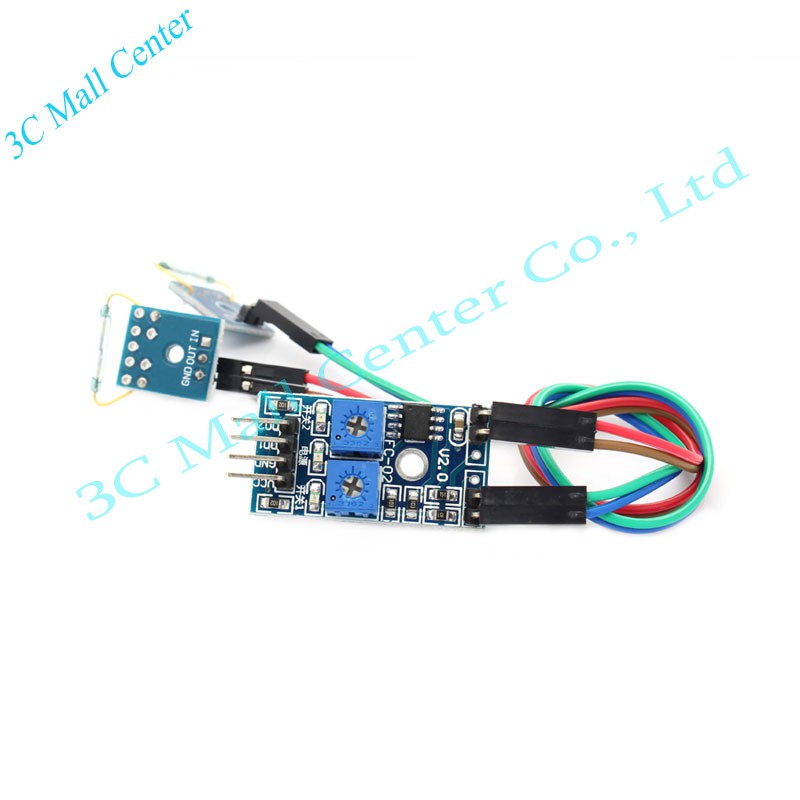
I selected two small reed switches* and glued a small magnet to the moving linear actuator table. These contacts could probably be directly connected to digital input pins, using a pull-up resistor, but I decided to maintain isolation on all external interfaces. So I used a common reed sensor module to connect these inputs.
*These switches are really fragile and I broke two of them while bending their leads and encapsulating them in shrink wrap tube. You need to order some additional ones as these cost next to nothing.![Reed contact module]()
-
6Step 6
Camera shutter release
My camera, a Nikon, has a 10-pin connector which allows for focus and shutter release:
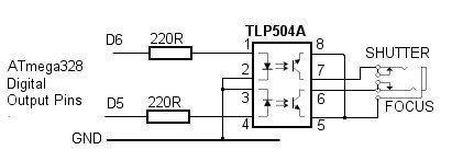
There are a couple of ways to actuate these inputs. In order to better isolate the camera from the controller I did not use a simple transistor or fet as switch, but was inspired by the following TLP504A (dual) opto-coupler design:![Nikon 10 pin connector]()
![TLP504A dual opto-coupler]() The opto-couplers for focus and shutter release require ~15mA to
activate.
The opto-couplers for focus and shutter release require ~15mA to
activate.Prototyping this circuit I found that the outputs (of ESP8266) could drain the required LED current. Thus I connected both LEDs using 220 Ohm esistors to +3.3V, and controlled the LED using two output pins.
-
7Step 7
Power supply
Last but not least. The parts used have different power requirements. Most voltage regulators can convert a higher in a lower voltage. So in order from high to low:
- 230VAC to 19.7V laptop power supply
- 12-48V stepper motor driver
- 4-40V to 1-35V LM2596S DC-DC 3A converter set to 5V
- 5V LCD panel, I2C LCD controller, I2C extender
- 5V to 3.3V regulator in the ESP8266 D1mini controller.
- 3.3V reed contact module, opto couplers.
To measure power usage (or battery condition if connected) the input power is routed through an AN219 current and voltage measurement module. This module is connected using the I2C bus.
-
8Step 8
Processing focus stack
The outline is known... I 'only' have to make it so:
- Running on Linux
- Accepting Nikon (D200) RAW images
- I love Java, but might end up with a command line script first.
- Convert RAW into whatever the next steps require
- Align image stack
- Stack by selecting pixels with highest contrast
- Convert whatever is produced into editable format (GIMP/Darktable/JPG/PNG).
- ?
- ?
- Profit!
(under construction)
FoocusStacker
Automate the creation of a focus stack by controlling the photo camera and a linear actuator.

 The opto-couplers for focus and shutter release require ~15mA to
activate.
The opto-couplers for focus and shutter release require ~15mA to
activate.
Discussions
Become a Hackaday.io Member
Create an account to leave a comment. Already have an account? Log In.