esben rossel
-
TCD1304 with the STM32F401 black pill
08/26/2023 at 07:09 • 0 commentsIt's been on the todo list for a long time, but I've finally come around to (re)writing the firmware using the STM32CubeIDE and for a version for the stm32f401 "black pill".
It's implemented with LL and HAL. LL is used for the timers, adc, dma and gpios, while HAL is used for the virtual com port via usb.
Live-view is quite a different experience with the a frame-rate > 10 Hz compared to the UART firmware's 1,4 Hz (limited by the fixed baudrate on the nucleo-board's st-link).
As usual, find the latest source code and binaries on tcd1304.wordpress.com
-
TCD1304 / TCD1254 .... potato tomato
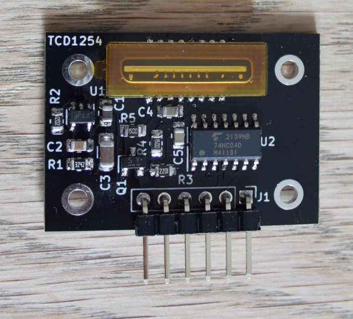
06/20/2022 at 19:11 • 0 commentsSo someone needed to drive and read the linear ccd TCD1254GFG and it turns out that the driving pulses has the same timing requirements as the TCD1304, so the firmware for the TCD1304 required very little modification to work with the TCD1254.
The TCD1254 comes in a different package, so it also required a little work to make a circuit board. But less saying and more doing:
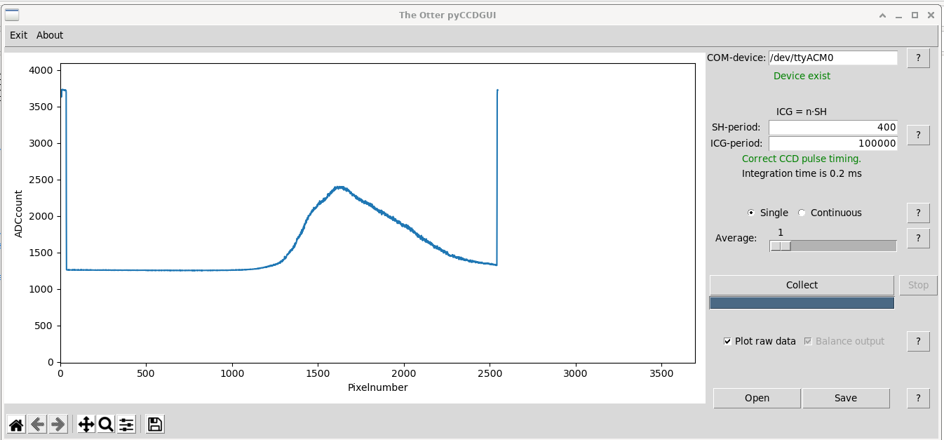
![]()
but not too much doing ..for instance I didn't bother scaling the x-axis here
![]()
and also, I've only made an STM32F401RE-version ()UART). I'll get around to fixing up the STM32F103 and the STM32F405 during summer, and perhaps even that STM32F303 I started and didn't complete because life suddenly made different plans
-
Double-vision
09/18/2019 at 19:56 • 0 commentsThis is not really a new feature. I made the first double-CCD firmware two years ago for a group of students in Germany. I forgot what they used it for, but they paid me in delicious german food.
I've since received a couple of requests for this feature from others, and rather than do a per-bratwurst-offering, I've decided to include it in the downloads-section at tcd1304.wordpress.com. There you'll also find a more in-depth walkthrough about considerations to make before changing the 4 or 5 lines of code required.
The long story short is that you can drive and read up to four CCDs with one STM32F401RE nucleo with an MCLK of 2,0 MHz. If you lower the CCD-clock, you can get away with up to eleven CCDs (my back-of-the-envelope calculations say). Of course you may run out of gpio's for ADC-input with that many CCDs, I haven't checked.
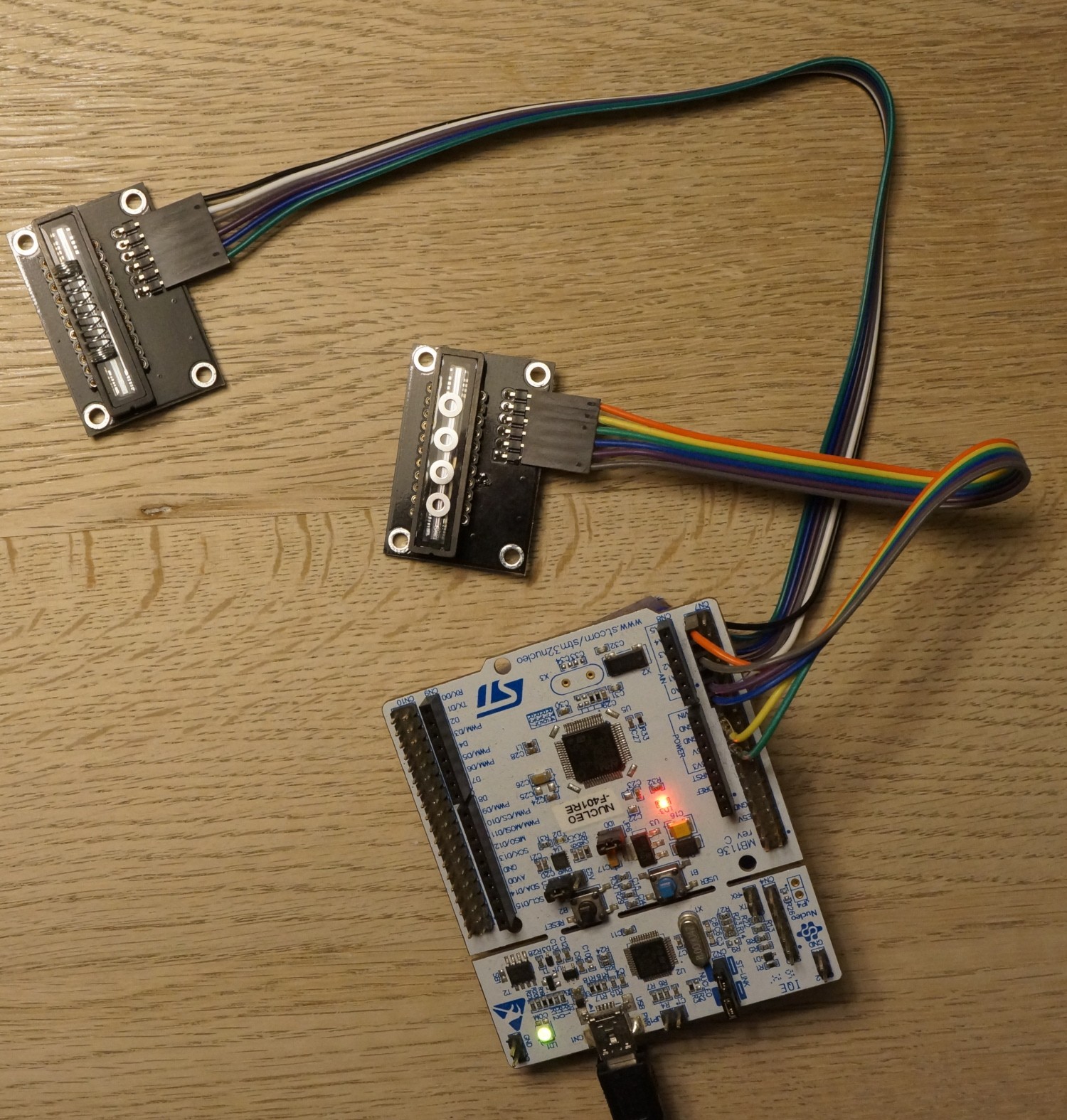
Anyway, here are some pictures.
![]()
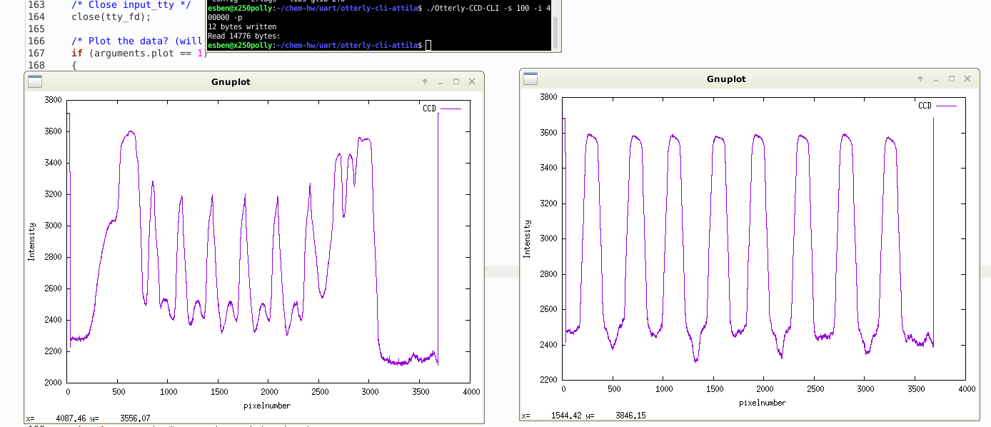
One CCD is covered with M2-washers, the other with ball-point pen spring. Here's what's captured:
![]()
-
Live-view
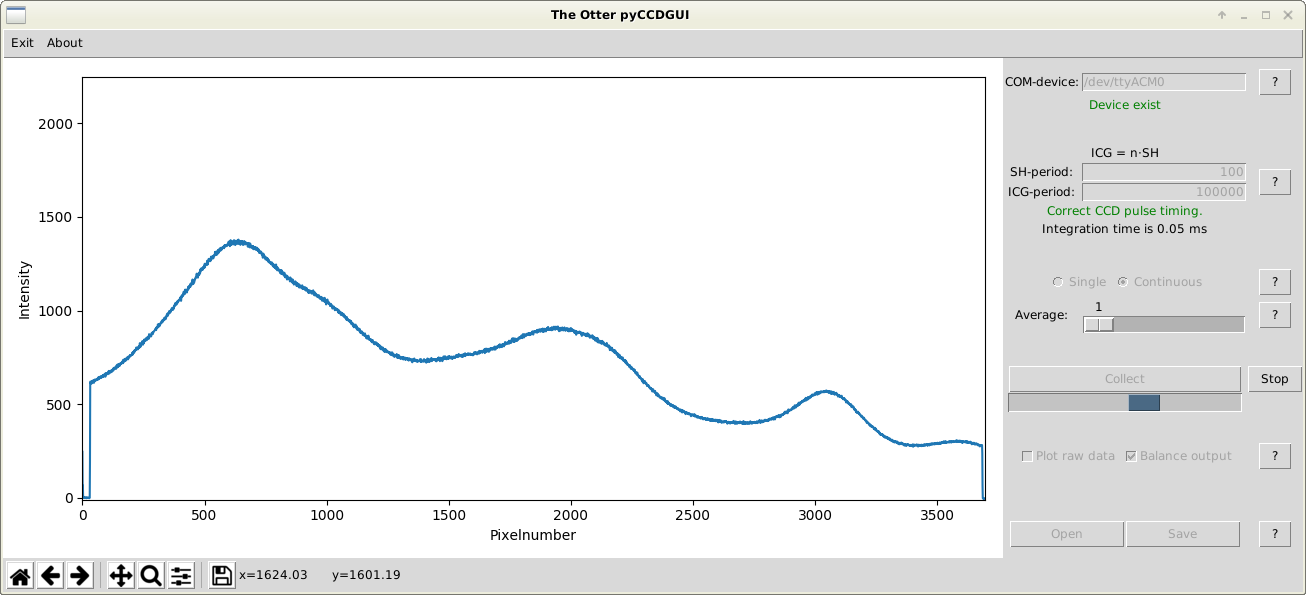
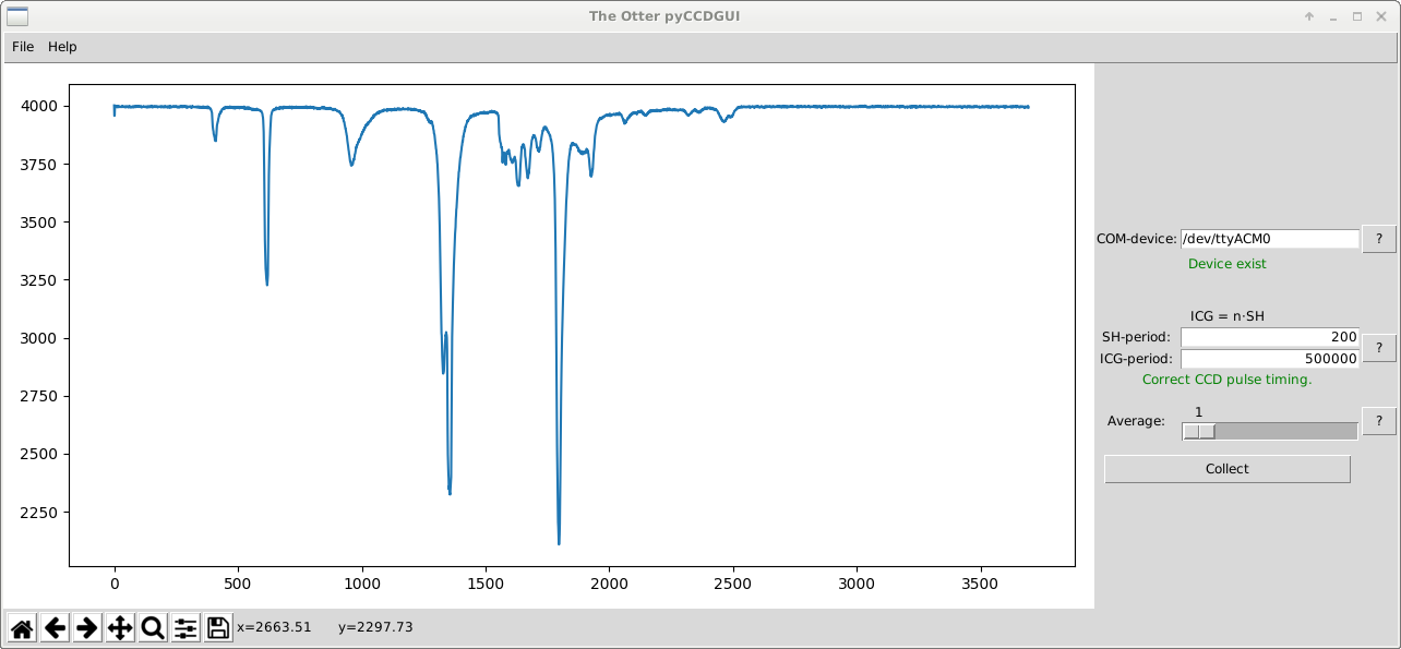
04/08/2019 at 10:14 • 0 commentsThe pyCCDGUI has received a lot of love this weekend. I'm most proud of moving the serial port handling to a separate thread, so the GUI remains responsive during long integrations, but the most interesting new feature is probably the "live-view".
Ok, so it's not super lively with the nucleo F401 which can only transmit at a frame-rate slightly higher than 1 Hz (because of the slow UART-connection to the ST-link), but with the STM32F103 where there's real USB, the pyCCDGUI can now read the TCD1304 and update the plot at up to 9,5 Hz.
There's also a few other new things (filehandling, a flashy new progressbar, compensation for shift register imbalance and few updates to the help-section). Check it out for yourself. Files are available at tcd1304.wordpress.com
Here's a screenshot for the impatient:
![]()
I've not yet updated the firmware for the STM32F405 to support continuous output, so I cannot yet report the frame-rate with this mcu.
-
STM32F103 blue pill driver for the TCD1304
03/03/2019 at 11:27 • 0 commentsThe blue pill is very popular (and cheap), and I've spent this weekend porting the TCD1304 driver firmware to it. It's a less capable chip than the STM32F401, there are limits to the applications. Most importantly, it doesn't support integration times longer than 82 ms.
The specifications are:
- USB-connection
- MCLK of 800 kHz
- max t_int is 2¹⁶ / 800 kHz = 82 ms
Pin-out is:
- OS - PA1
- ICG - PA10
- SH - PB4
- MCLK - PA15
The board attaches as a virtual com-port, so the usual tools work ie. the pyCCDGUI and the CLI (UART).
Everybody loves pictures, so:
![]()
![]()
![]()
Get it while it's hot. Go to tcd1304.wordpress.com
-
Platform independency
08/19/2018 at 16:19 • 0 commentsI'll keep this short. I've written a graphical user interface for python 3. pySerial handles communication, so there are no ties to Linux and/or macOS with this one.
![]()
The program can be found in the files-section and on tcd1304.wordpress.com of course.
And here's the stand-alone windows executable
-
Noise
06/28/2018 at 17:32 • 0 commentsDriven by a nucleo board, the signal from the CCD in the typical drive circuit with a low-noise low drop-out voltage regulator exhibits roughly ±4 mV of noise. This figure is the same for the custom STM32F405 board, however because the opamp has a gain of ca. 2, the S/N-ratio has improved with app. 50%.
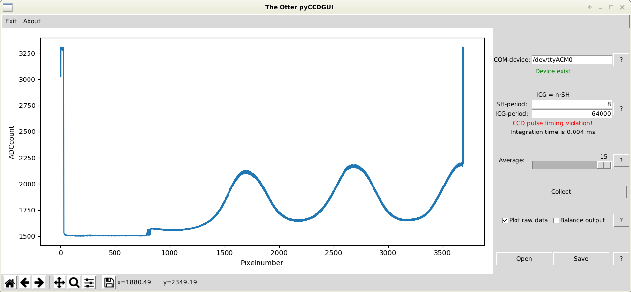
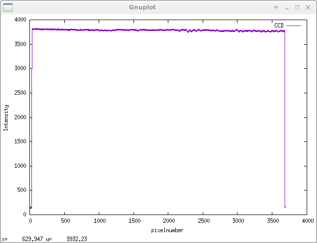
Still, the output looks kind of fuzzy, as seen in this figure showing the CCD at close to saturation:
![]()
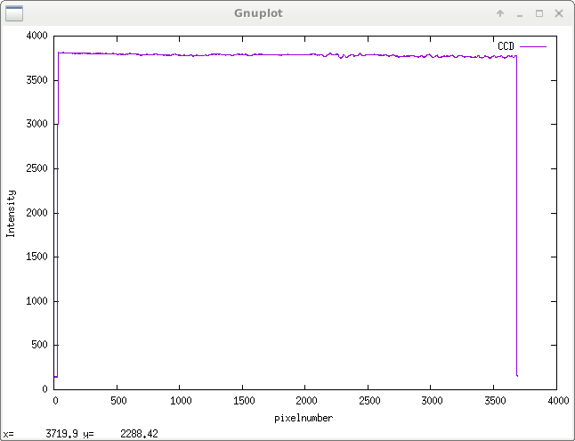
However, because the noise-level is now a little lower, it's become very easy to estimate the CCD's register imbalance, and when correcting the data for it, the same data now looks like this:
![]()
I'm not sure I'll get a cleaner picture than this. I'm certainly not in the mood for trying.
-
Straight to USB
06/27/2018 at 13:08 • 0 commentsThe UART-firmware uses the USB-connection on the nucleo's ST-link, and it's limited by the bitrate of the ST-link's USB-UART connection.
The latest firmware is written for the STM32F405-board from this project:
https://hackaday.io/project/56937-stm32f4inputs
and it uses the USB-controller in full speed mode (12Mbps) to communicate directly with the PC.
I've used ST's USB-driver (SPL-version), and the MCU presents itself as a virtual com port, so the CLI and GUI for UART can be used without modification for the firmware.
Clocks, PWMs and communication are all working. I'm going drinking, so tests with a TCD1304 in place will have to wait.oh right and the firmware can be found in the files section.
-
Setting the CCD up with a custom MCU-board
06/16/2018 at 05:59 • 0 commentsI've ben working on a custom STM32F405 board with better analog options in a separate project.
The key difference is the utilization of an opamp on the input, to squeeze the last bit out of the STM32F4's 12-bit ADC.
The opamp circuitry looks like this:
![]()
For reasons I don't fully understand, the opamp's input and feedback resistor values affect the output from the CCD's typical drive circuit, but changing the resistors to:
![]()
there's no clipping of the output. I guess my quantum chemistry professor was right, you can't measure a system without changing it.
-
100 Hz frame-rate for the TCD1304
12/24/2017 at 16:24 • 0 commentsWith a slight redesign of the SPI-firmware and the accompanying command-line-interface, I'm proud to present a record high (for me at least) frame-rate for the TCD1304 of theoretically 125 Hz.
I'll be conservative and state that 100 Hz is possible. Because of x-mas I'm away from my scope, so a proper speed-test will have to wait.
The very short version of the story is that wiringpi has been replaced in favour of pigpio, and that SPI-communication is triggered by monitoring the logic state of one of the nucleos GPIOs.
Oh and you can collect 65535 integrations in one go.
https://erossel.wordpress.com/2017/12/24/high-framerate-125-hz-tcd1304-firmware/
or look in the source code.
Downloads are available at https://tcd1304.wordpress.com
The UART-firmware is still crawling away at a pace of just above 1 Hz, but with lots more convenience.
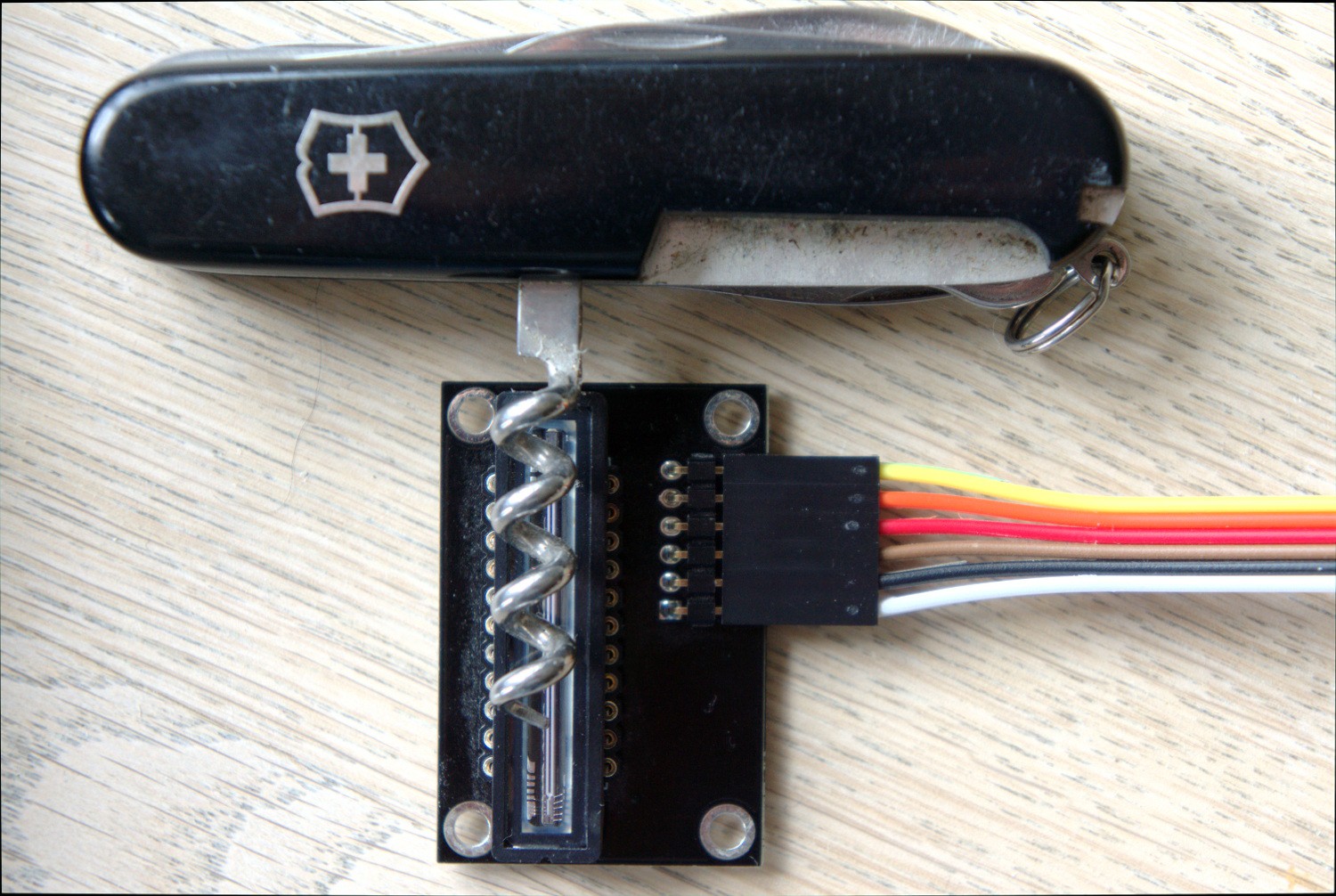
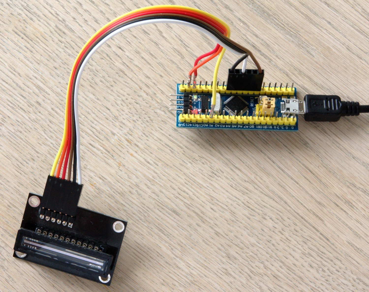
Linear CCD module
TCD1304-based linear CCD module driven by a Nucleo F401RE, an STM32F401 black pill or an STM32F103 blue pill