esben rossel
-
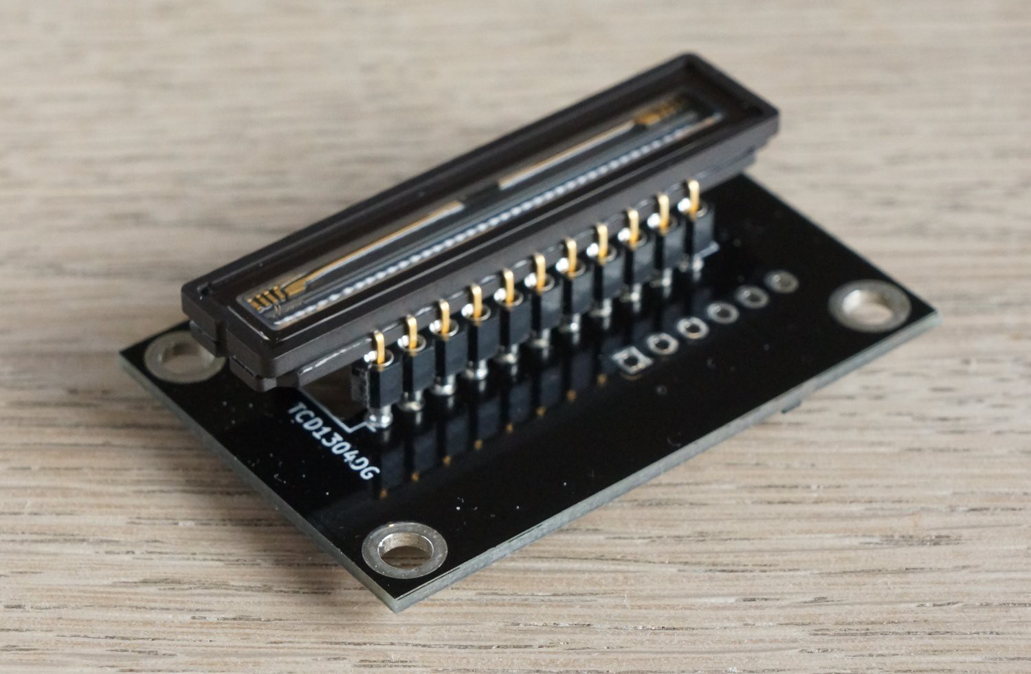
New PCB: 12% smaller, 12% cuter, 24% easier
11/12/2017 at 14:44 • 0 commentsThe latest firmware and PCB is here:
![]()
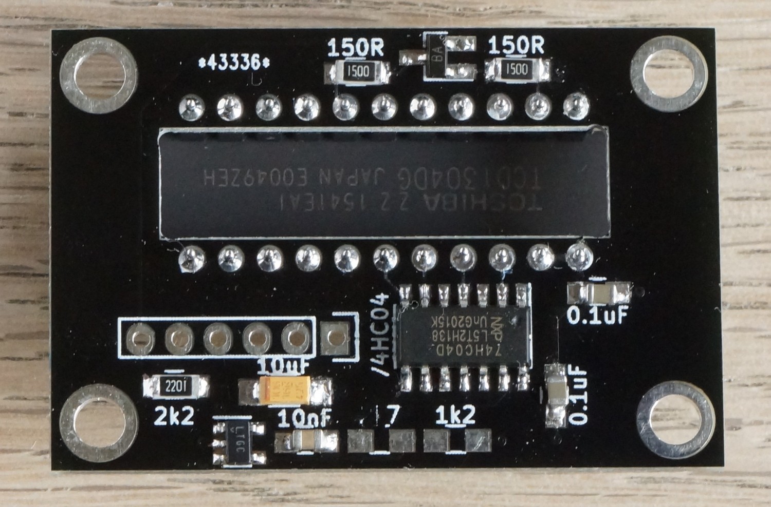
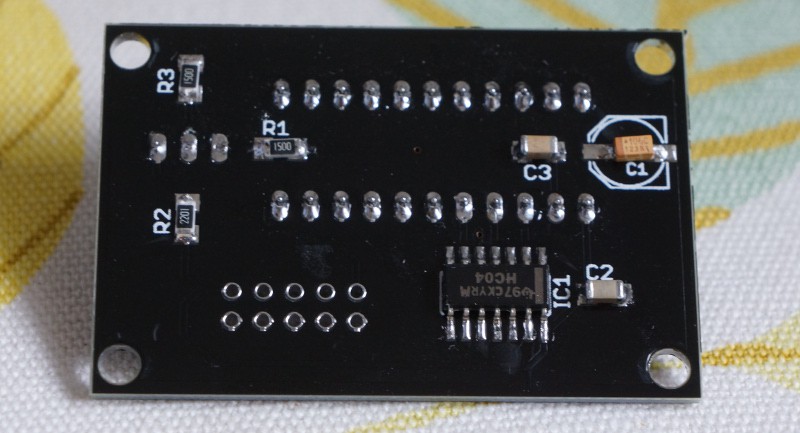
besides from being smaller, there's now a regulator on the supply voltage:
![]()
Vs = 1.22 (1 + R₂/R₁) = 1.22V(1+ 2.7kΩ / 1.2kΩ) = 3.96V
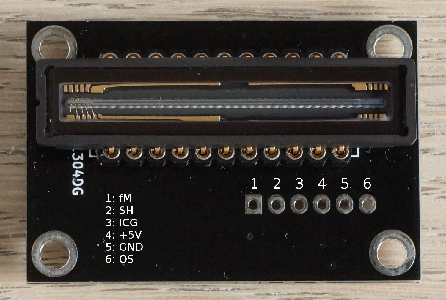
The pinout has been changed:
![]()
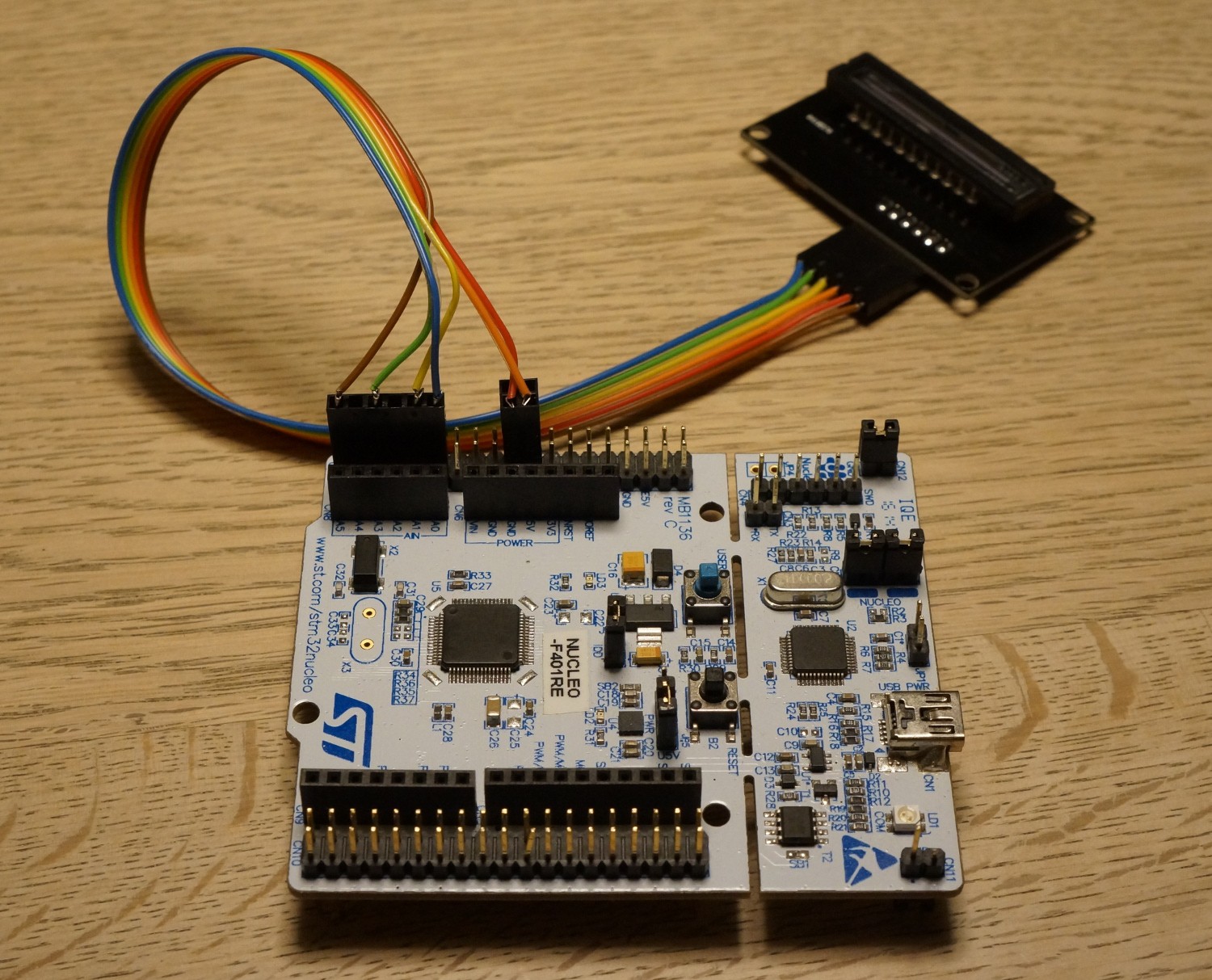
and so has the GPIOs on the STM32F401re, so everything's much easier to connect:
![]()
(The CCD-PCB in the picture is a prototype)
As always go to https://tcd1304.wordpress.com to be sure to get the latest and greatest firmware and software, and instructions to match.
The PCB (slightly improved compared to the one in these images) is available directly from http://dirtypcbs.com/store/designer/details/8475/6065/tcd1304-4vn-zip
It's only the UART-firmware that has been updated. The SPI-version will follow shortly.Both firmwares (SPI and UART) been updated with the new GPIO-configuration:
- fM on PB0
- SH on PA1
- ICG on PA0
- OS on PC0
-
Windows support
08/18/2017 at 16:34 • 0 commentsJens-Ulrich Fröhlich has written a Java-based graphical user interface for the Linear CCD module for Windows, and I must say I'm impressed. It has many of the features that I wanted to include in my early attempts at a GUI.
And it comes at just the right time. In this school year I will 'convince' my students to try and build their own spectrometers, so a Windows interface is greatly appreciated, as my nerdier students prefer this OS.
Take a look at his blog:
and the github-repository:
-
MacOS X support
05/01/2017 at 13:06 • 0 commentsIt turned out to be very easy to get a working Otterly CCD CLI for MacOS X, as the operating system uses the same underlying tty-system as linux.
It was literally just a matter of getting my hands on a Mac (that was the hard part) and setting up the proper environment for compiling.
One needs to install:
- xcode
- command line tools
- glib
- pkg-config
The compiler options need to be modified slightly (link to argp) so there'll be separate MacOS download (shortly).
The tty-naming scheme on MacOS X is confusing. The serial device to connect to is not tty.usbmodemxxx but cu.usbmodemxxx
Of course if you don't care for compiling it yourself, you can just use the precompiled binary. In that case, the only dependency is glib
-
Command line diy line camera
03/18/2017 at 17:51 • 0 commentsTo make the lives of anyone wishing to use the linear CCD modules easier, I've made a CLI. Hopefully it'll make the software side of things more modular.
In the same time I have given the SPI-enabled firmware an update to give it all the benefits of the improvements to the UART-version, and the two should now be very similar in performance, except of course for the 150x speed-advantage of SPI.
At the time of writing there's only a CLI for the SPI-version of the firmware, but a UART-CLI will follow shortly.There's of course a CLI for both SPI and UART.
As usual go to tcd1304.wordpress.com for downloads, details etc. -
Firmware revision 2.0 (MHz)
02/03/2017 at 06:12 • 0 commentsThe following notable changes have been implemented:
- CCD fM changed to 2.0 MHz,
- CCD driving GPIOs moved away from ADC-in
- Certain GPIOs pulled down for virtual GND.
- CCD fM is now user configurable at compile time (and all timing requirements are met dynamically)
- ADC sampletime increased
- bugs fixed
For download and more details look in the source code and here: https://tcd1304.wordpress.com
-
UART is in / rpi is out
12/28/2016 at 17:46 • 0 commentsThe raspberry pi is no longer strictly needed, as the new UART-enabled version of the firmware allows for direct connection to any (linux/BSD) computer. Using UART will (eventually) allow for "continuous" reading of the CCD and data-driven events.
-
A second look at DMA plus a firmware-update
07/08/2016 at 22:21 • 2 commentsThe firmware was not stable. I experienced crashes. They were infrequent, but still very annoying. Fiddling with the nucleos UART I'd been running into traps of interrupts - there's probably a technical term for it, but I don't know it.
Long story short: The DMA-controllers in the STM32F401RE can run in normal or circular mode. In the normal mode, the DMA stops once the read/write buffer is full. In the circular mode it ..runs in circles and overwrites the buffer from the beginning once it reaches the end.
The good thing about circular mode is you don't have to reinitialize the DMA every time you need to start over. This is especially practical if what you're doing is time-critical ..like say digitizing the output from a CCD.
There are most likely better explanations, but hopefully this gives you a picture of the situation.
The catch, of course there is one, is that the DMA must be suspended if you want a chance to look at the data. I thought I was very clever to that with an interrupt. Piece of cake. Except suspending the DMA causes the same interrupt. Very loopy - yes pun intended.
I spent the entire evening speculating on how to break this loop, and finally, completely off the trail, I found a comment about when to start the ADC with software and when not to.
If you've been over the code you'll know the ADC is paced by one of the nucleo's timers. This means there's no need to start it with software. It also means that the ADC stops when the timer stops. Instead of suspending the DMA in the DMA-interrupt (causing an interrupt inside an interrupt), the DMA-interrupt now disables the timer pacing the ADC.
With the ADC on hold no DMA-requests are generated, effectively suspending the DMA. And so far no crashes :)
Firmware files will be updated asap.
-
First steps with UART
07/08/2016 at 14:57 • 3 commentsI will keep this short.
Transmitting data with DMA+UART is now working. I can send and receive data through the nucleo's built-in ST-link. However the maximum baud rate I've been able to achive is 230400bps, which means that transmission of data worth a full CCD takes:
I won't have access to an oscilloscope until august, so I can't verify the figure, but from simple tests it does not seem completely unreasonable.
The same amount of data is moved in 4ms with SPI, so communication with UART is roughly 80x slower than with SPI. It's acceptable, but I really wish I could get it under 100ms.
The 230400bps is with 16x oversampling. The STM32F401 can also do 8x oversampling, but neither setting gets me a higher baud rate.
-
Communication protocols
07/07/2016 at 17:33 • 0 commentsThe first versions of the firmware communicated using UART through the built-in ST-link. Calling it communication might be a bit of a stretch though. The integration time was fixed to whatever value was set during compilation. Every time the CCD was read, the pixel-values were sent to the termnial by redirection of print with the newlib_stubs library.
All in all a very clumsy way to transmit the data, and above all it was slow, and by slow I mean 1-2 seconds (I don't remember exactly how slow).
After reading up on the various communication protocols available on the rpi, I settled on SPI - not because it was the right choice, but simply because I could understand it. The rpi's SPI is annoying though, because it insists on being master, so the data from the CCD is transmitted at the will of the user and not the hardware, potentially creating interrupt conflicts - I think¹. On the upside it's fast: each transmission of 7.4 kb of data takes only 4ms.
However I find myself wanting to go back to UART. Firstly it would allow the mcu to send data whenever, secondly - and more importantly - it would enable me to cut the ties to rpi and make the module more ..universal: With UART the module could become a readily usable part for custom made spectrometers in university/teaching labs and the fantastic WINSPEK32 could probably be used for data-collection.
So that's on the program for this summer holiday - provided I find the time between travelling.
[1] Every once in a while I experience firmwarecrashes, and I suspect the interrupts are to blame. However, I'm an idiot at debugging, so I actually don't know what's going on.
-
Keeping it small(er)
06/13/2016 at 10:20 • 0 commentsThe linear CCD module is a central component in the OtterVIS LGL spectrophotometer, and for this everything needs to be as compact as possible, so I've replaced the (relatively expensive) electrolytic capacitor in the module for that project with a tantalum cap and placed T1 under the TCD1304. Here's the slimmed down version:
![]()
Here you see it from the back. C1 has been replaced with a cheap tantalum capacitor. Don't laugh at my SMD soldering skills..
![]()
All in all it buys me the few extra mm that I need to keep the OtterVIS spectrograph inside the build volume of the 3D-printer.
Linear CCD module
TCD1304-based linear CCD module driven by a Nucleo F401RE, an STM32F401 black pill or an STM32F103 blue pill