Prithvi
-
ERC works with no errors !! *said no hardware dev ever*
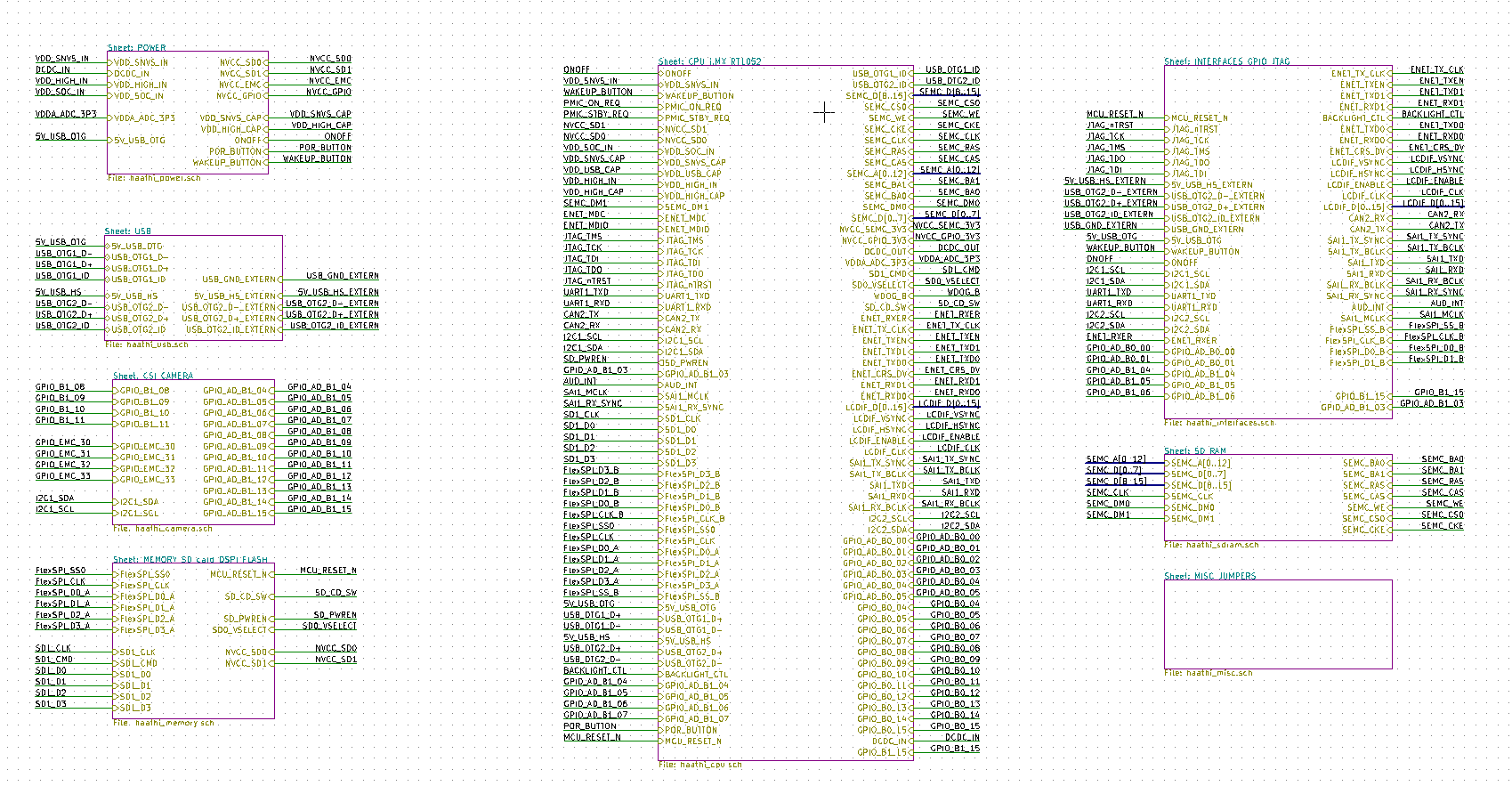
04/21/2018 at 13:42 • 0 commentsAfter some really tedious inter-sheet wiring done with a smart use of the KiCAD’s `Insert` button feature for replicating the last step, here we are:
![]()
We finally annotated the schematic! :D Woo-hoo!
But... we also ran ERC :| :( and found a couple of issues. 12 Errors and 42 Warnings (it’s always 42 :P) didn’t seem so bad considering a 7 sheet hierarchical schematic and the team’s first brush with a design this complex (except for Abhishek: check out his entry for last year’s Hackaday Prize: BeagleLogic).
The major ERC errors had occurred because of the way we had used (and not used) PWR_FLAG symbols in the schematic. Once we removed and placed PWR_FLAG at the right places, the errors related to power pins were all gone.
Currently we are down to 23 warnings in the ERC, mostly unconnected pins because of struggles in fully breaking out all the interfaces we want to. The challenge we’re facing right now are the decisions that we have to make because of the way pins are muxed on the SoC in terms of giving preference to one peripheral over another. For instance, the camera CSI pins are muxed with the Audio interface pins because of which we’ll wire up the camera by default, but provide 0 Ohm resistor packs as a way of switching to Audio (SAI) functionality for those pins if anybody wishes to.
We expect these issues to be resolved in the coming week along with yet another full review of the schematic. Additionally, we’ll finish up the footprints for all symbols and post a log update soon before we start laying out this elephant (haathi) of a board.The latest PDF of the schematic can be viewed here - https://github.com/botmayank/haathi_cam/blob/master/kicad/pdf/haathi.pdf
-
Schematic 90% complete
03/25/2018 at 01:01 • 0 commentsThe schematic capture for the Haati board is 90% complete. We just have to pass the schematic under a rigorous to make sure that we aren't messing something important. And it comes at a time when A1 version of the silicon of i.MX RT 1050 has become available at Digikey and the migration guide from A0 is released.
To choose between power sources, the user can use a slider switch on Haathi board to select from the following options:
- With a TPS62142 handling the step down, a battery input of up to 17V.
- USB supply input.
A coin cell holder is provided to power up the low power real-time clock and non-volatile highly protected storage section of the SoC.
Among the boot options, the user can boot from either the Quad SPI flash memory or the SD Card. This can be change by selecting the boot mode on a DIP switch. Also possible is a Serial downloader from USB OTG and UART.
Haathi Board
Haathi Board aims to be a low cost and developer friendly platform for the iMXRT1050 SoC