-
Free project to a good home
06/05/2018 at 12:52 • 0 commentsI started this project with thoughts of entering into the power harvesting challenge, but I'm just not feeling the joy - too many other things to work on at the moment. So, I'm offering the project to anyone who wants to run with it. I can supply two generators ("5V" "12V" versions) and a coupler that fits a standard shower hose. I'll ship these parts to you for free, using up to the amount of seed money this project garnered in the community vote of the first round (TBD). This will probably cover any shipping within the U.S., but international shipping might be a little more.
I think this project has potential, and it's not really an original idea of mine, so I'd hate for it not to be explored during the contest just because I'm off working on something else.
If this interests you at all, or you have another suggestion for the project, let me know!
-
Backup Power Architecture
04/22/2018 at 15:01 • 0 commentsFor some applications, a backup power source will be desired for periods of low water use. An example might be an IoT frozen pipe sensor, which should continue to work even if you are not running the water often enough to charge the batteries.
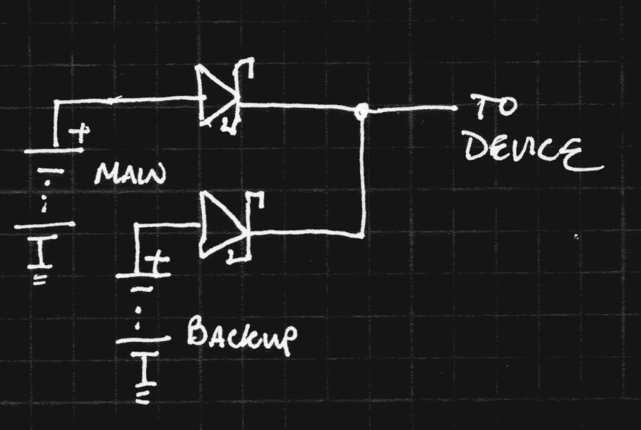
I envision a power-switching circuit to cut over to a lithium primary battery during such periods of "power drought." The simplest way to accomplish this is with the use of two Schottky diodes:
![]()
The problem with this circuit is that the forward voltage drop of the diodes reduces the battery life. Although for very low current drains, this may be sufficient, for any application which requires periodic high pulse currents, the forward voltage drop becomes a limiting factor. Additionally, the reverse leakage of Schottky diodes can be relatively large, causing unnecessary power drain.
A more efficient solution can be constructed with any number of commercial "smart diodes" or power-ORing ICs developed specifically for this purpose. These devices use a comparator to determine which input voltage to use, and switch MOSFETs to efficiently select the appropriate supply. Although these devices can be more efficient than a simple diode-based solution, the added efficiency comes with added cost and complexity.
I'm currently surveying the offerings from various manufacturers to determine if any of them are suitable for this power supply module. It may be that the module can be designed to accept either a simple diode-based switch or a more sophisticated IC-based solution for different end uses.
At this point, I haven't ruled out the possibility of designing my own ideal diode controller for power switching. Although a circuit constructed from individual comparators and MOSFETs probably couldn't compete with commercial offerings on price, comparators and other components may come for free as peripherals on a microcontroller. In this case, a home-brewed solution might make sense.
-
Down the rabbit hole
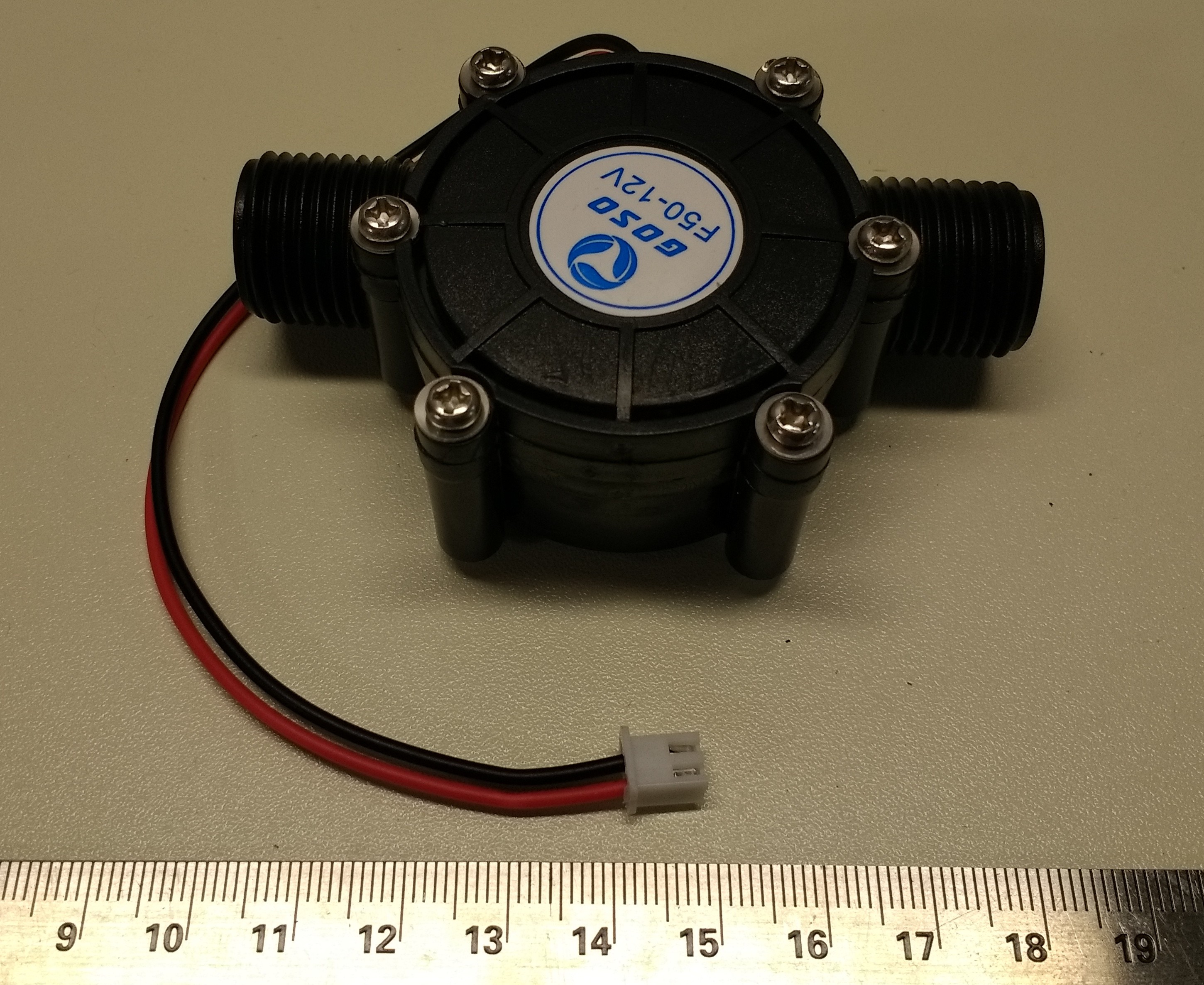
03/24/2018 at 00:02 • 0 commentsWhen manufacturers use security fasteners on a device (like on a hard drive), they're saying they don't want you to open it. When they use Phillips, I can only assume you're supposed to tear the thing apart. So, guess what happened a few minutes after this arrived in the mailbox?
![]()
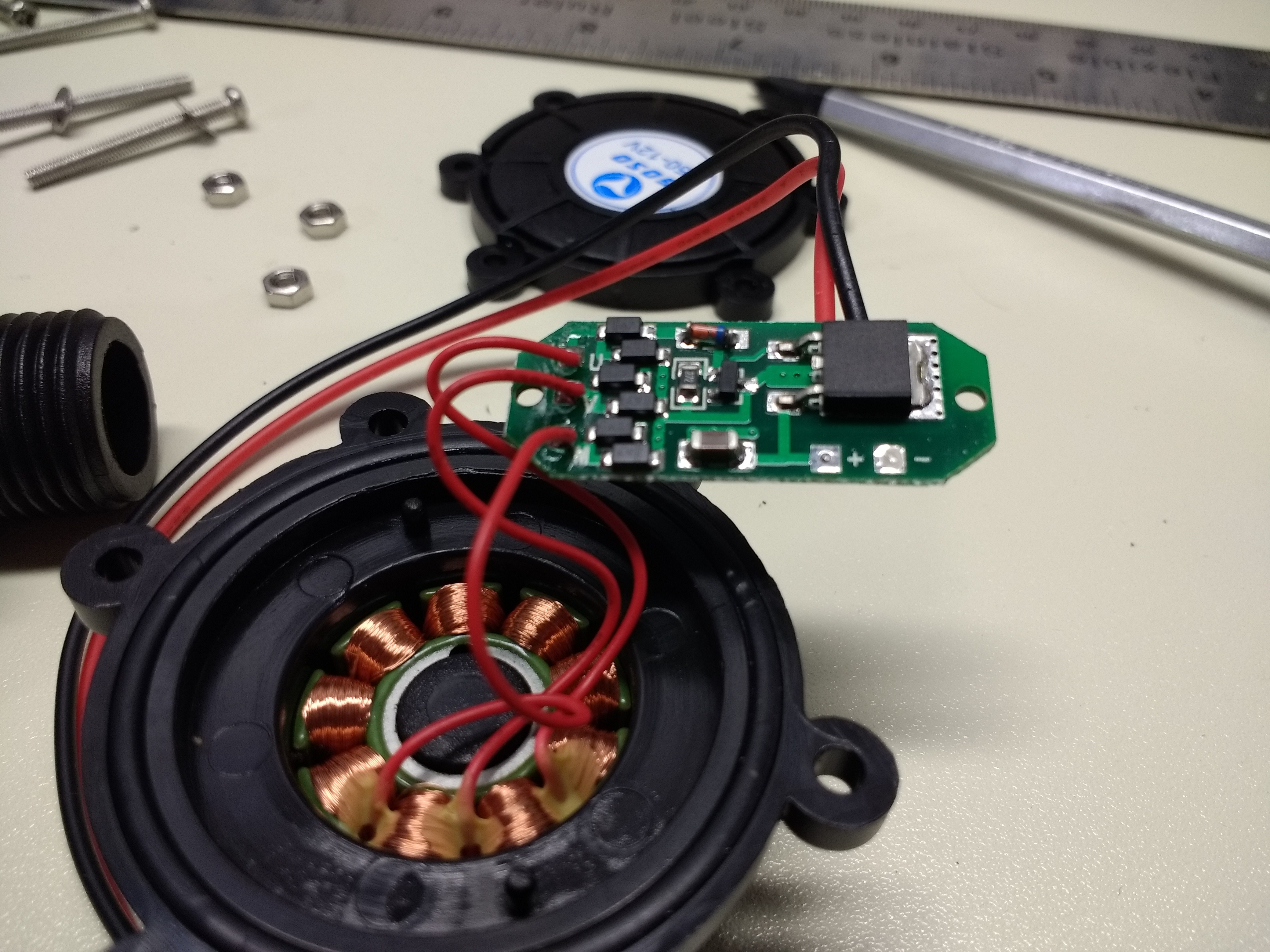
There was minimal documentation on ebay about what these things actually are, but they came in 5V and 12V versions. I bought one of each (from different vendors), and the 12V happened to arrive first. I figured they were probably wound with a different number of turns or something like that to produce different output voltages. Imagine my surprise on opening the case and finding this:
![]()
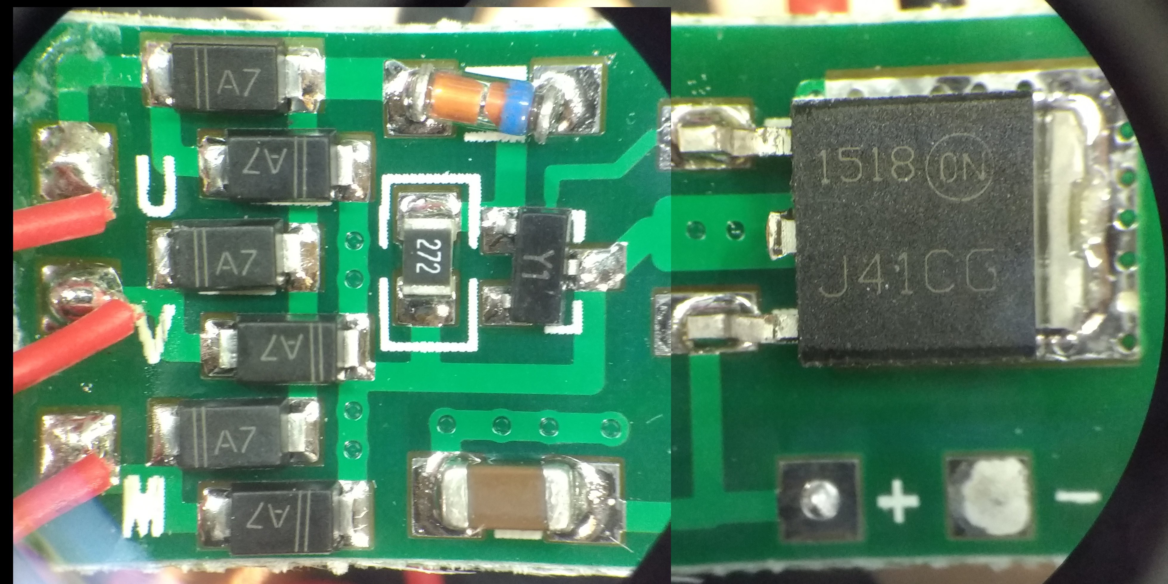
The 9 coils are wired as a 3-phase generator and there's a circuit board in there! OK, time to figure out what it does. I couldn't get the whole PCB into the frame of the inspection microscope, so I stitched this image (poorly) from two shots:
![]()
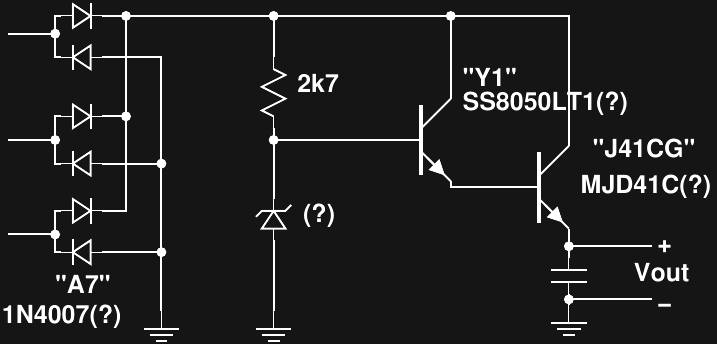
The three red wires on the left come from the coils. The six SOD-123's are obviously diodes of some sort in a 3-phase bridge rectifier. It turns out "A7" is a common code for SMD packages. These could be 1N4007 A7's. If so, replacement with appropriately-rated Schottky's might improve efficiency. I'll measure the forward drop after removing one from the PCB.
From what I can tell, this is the circuit:
![]()
I'm assuming the glass diode is a zener since it is reverse-biased by the 2k7 resistor. The SOT23 appears to be a SS8050LT1 NPN transistor, while the larger TO-252 a power NPN, MJD41C. It seems fitting that I was only able to decode the component markings after searching on ebay, where I bought the mystery generator in the first place...
Anyway, this looks like a crude zener-based voltage regulator for charging 12V batteries. When I get a chance, I'll re-assemble and test it. In the end, I'll probably end up tossing this PCB and replacing it with something more suited to my end goals.
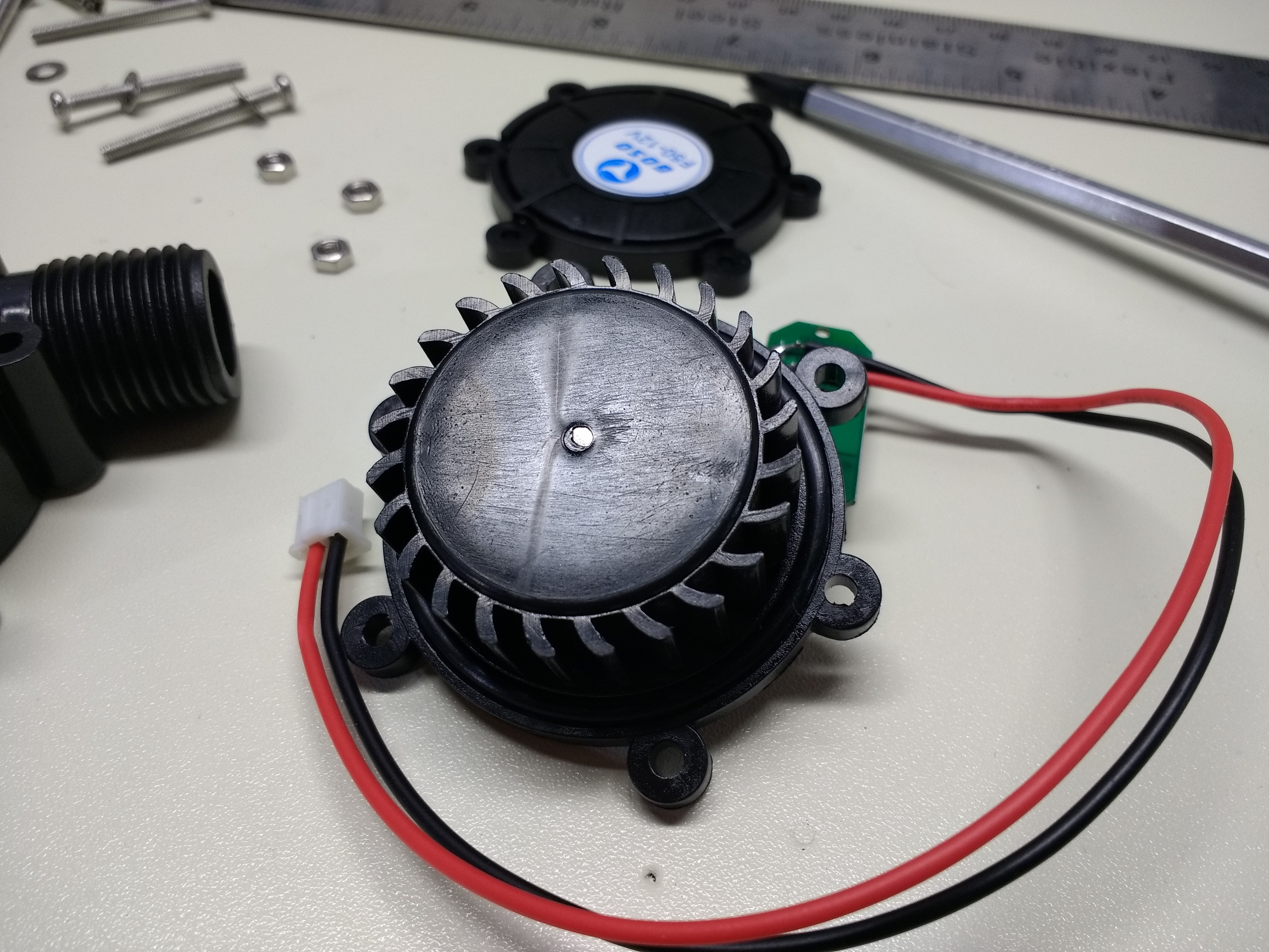
The other side of the assembly shows the turbine itself:
![]()
I'm not sure how well sealed this whole thing is or if the plastic is food-safe (doubtful!) and I noticed some tiny solder balls on the PCB, so I'm thinking for now I'll keep it out of the potable water lines.
 Ted Yapo