-
1Step 1
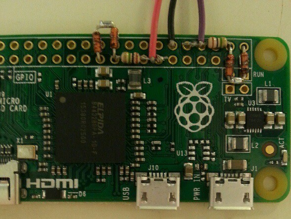
Build it like this. Orange and purple are inputs, black is ground.
![]()
CALIBRATION
NOTE: These instructions are for a character device kernel module. I will re-write them when I finish a proper sound device kernel module. They're also horribly confusing - I'll do something about that too.
If you use my code as-is, you'll probably have some distortion and incorrect amplitudes. If you want an accurate display, you'll need to calibrate it.
![]()
To do this, you'll need a source of several calibration voltages. The easiest and cheapest way is a series string of five 1K resisors, with a 10K resistor at the end of the string. (In the above picture the clip leads are the inputs, and the black alligator clip is ground, The battery is connected by the red and black alligator clips at the top.) You can solder it together or use a proto board. The ends of this string are connected to a 1.5V battery: the battery positive to the 10K resistor, negative to the 1K resistor. Measure and record the voltages between each pair of resistors, with the meter ground lead connected to the battery negative terminal. A cheap DVM is quite adequate. The voltages should be at roughly .1, .2, .3, .4, and .5 volts. For each measured value, subtract the value from .5 and multiply the result by 300. These are the positive values. For the negative values, add .5 to the measured value and multiply the result by 300. Write these values on labels at each corresponding resistor junction.
Now connect a Pi ground pin to the battery negative lead, and both input leads to one of the resistor junctions. Make sure the kernel module is loaded, and compile and run the analog2screen program. It will display the capture values for SPI and PCM. Write down the value for each: use the average value displayed. Also write down the positive junction label value. Move the inputs to each resistor junction and repeat the measurement.
Now reverse connections: the inputs go to the battery negative, and the pi ground pin is connected to a resistor junction. Do the measurements like above, moving the Pi ground to each resistor junction in turn. You are, however, measuring negative voltages: use the negative label values. The final measurement is with the inputs connected to a Pi ground pin: this gives measurements for a value of 150. You should now have 11 measurements recorded for SPI and 11 for PCM. I know this isn't a very good description, so I've listed my values here to help you figure it out. These are for SPI on a PI 2:
OUTSPI-1364.82054.25245.48538.111731.815026.618322.421518.524815.128112.03139.3Next you'll have to use these values to generate coefficients for a linearizing equation. Since the Pi has Mathematica already installed, we'll use that. Enter your SPI values into a text file named spi.wm. The file contents should look like this:
data={{64.8,-13},{54.2,20},{45.4,52},{38.1,85},{31.8,117},{26.6,150},{22.4,183},{18.5,215},{15.1,248},{12.0,281},{9.3,313}}Fit[data,{1,x,x^2,x^3},x]Then run the following command:
wolfram < spi.wmThe output of the command lists the coefficient values.
Repeat the process for PCM, but instead use pcm.wm and edit pcmlin. After piScope.c is compiled the new values will take effect. Test it to make sure.

Discussions
Become a Hackaday.io Member
Create an account to leave a comment. Already have an account? Log In.