cb22
cb22-
It's raining, it's pouring.
06/05/2014 at 09:27 • 0 commentsSince it's winter here, I haven't had the chance to maiden the plane yet. It's just sitting next to my bed, and looking awfully sad. It's not so much the cold, but rather the rain and the wind that's a problem.
![]()
-
A small update
05/25/2014 at 09:50 • 0 commentsUnfortunately I haven't had the time to post much, but having said that, the basic platform is almost ready. I've mounted the motor, installed the servos, and am busy adjusting everything for correct CG.
Eventually (when they arrive) the flying wing will be carrying two 5000mAh 3S LiPo batteries from HobbyKing which will hopefully provide enough power for a decently long sustained flight. In the meantime, I've got my 3300mAh 3S LiPo hooked up, as well as weights, to balance out the plane.
I'd like to maiden it within the next few days, that's when all the little niggles will start coming out, and the tweaking begins.
-
Build in progress
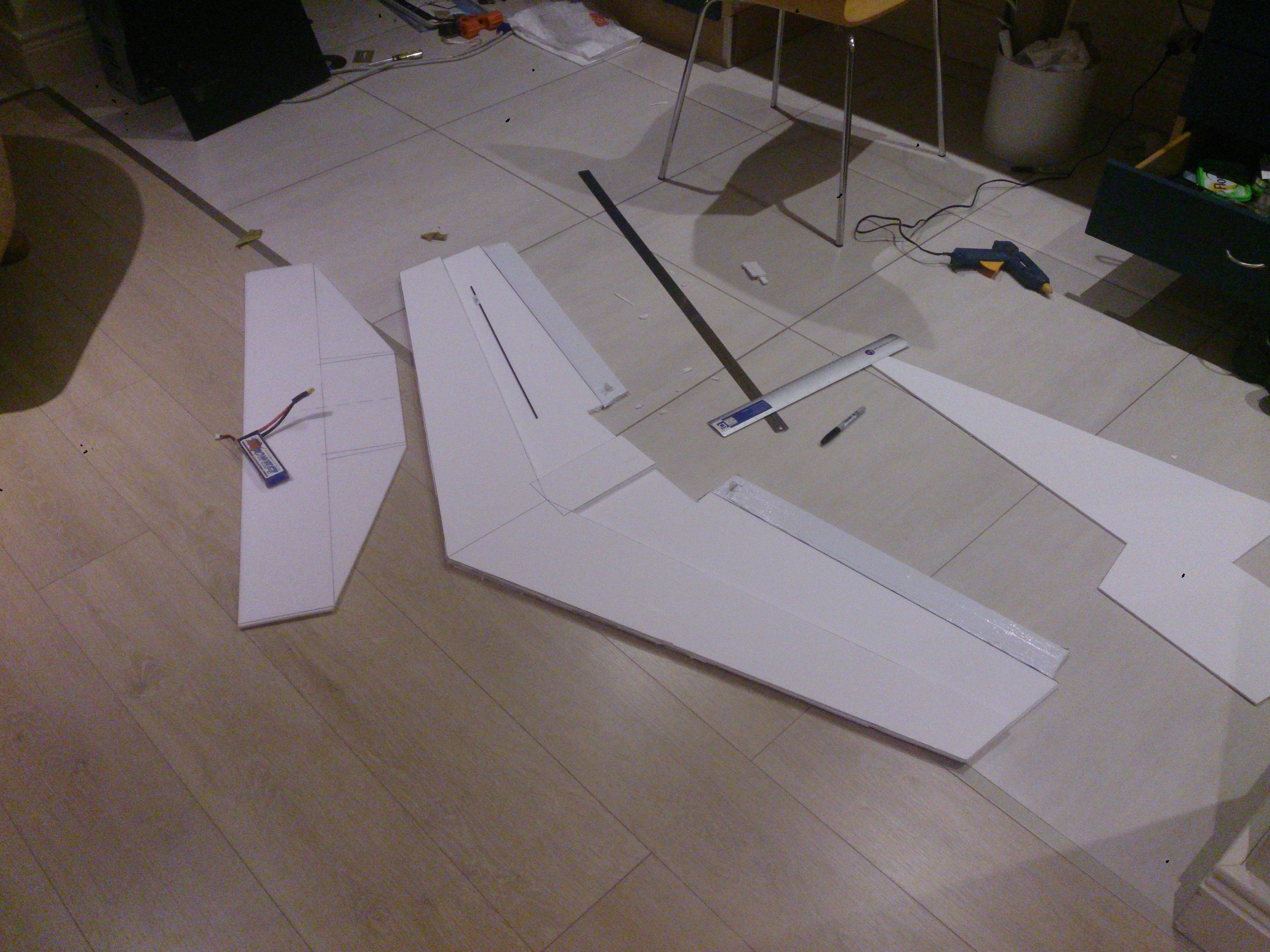
05/11/2014 at 19:19 • 0 commentsI've never used this particular foam board before - it has a paper covering on it which adds quite a bit of rigidity at the expensive of, well, being paper.
Since I had two sheets of foam, I stripped the one of its paper covering. This was a messy process, even though there are videos on YouTube showing people doing it in minutes, it took me ages with a hose pipe to get the thing clean. That's when I discovered just how much rigidity the paper actually added.
Anyhow, the build is coming along nicely, although I do need some more foam glue and carbon fibre spars. I think that if I had kept the paper layer on, the carbon fibre spars wouldn't even be needed. The whole thing will be "laminated" with duct tape anyway, which makes it substantially tougher and somewhat water resistant.
![]()
For scale, the long ruler in the picture is 1 m.
-
Designing the flying wing
05/08/2014 at 13:23 • 0 commentsFlying wings are tricky things - as I've learnt the hard way, the CG is extremely important, much more so than on a normal plane. (Compare with incorrect CG vs properly adjusted). This can quite limit your options in terms of component placement. In a pusher design, you'll need heavy batteries up front to bring the CG to the correct location.
A flying wing can be characterized by 4 basic parameters, the wing span, root chord, tip chord and sweep. There's a handy calculator online that will generate a wing as well as calculate the optimal CG location based on these parameters.
The next step was to choose these parameters to maximize both capacity and flight time. I'm certainly not an aeronautical engineer, but going from online reading, as well as other videos on YouTube, you can figure out how these parameters affect the overall performance of the wing.
Eventually, I thumb sucked some design parameters (deep-link to the calculator):
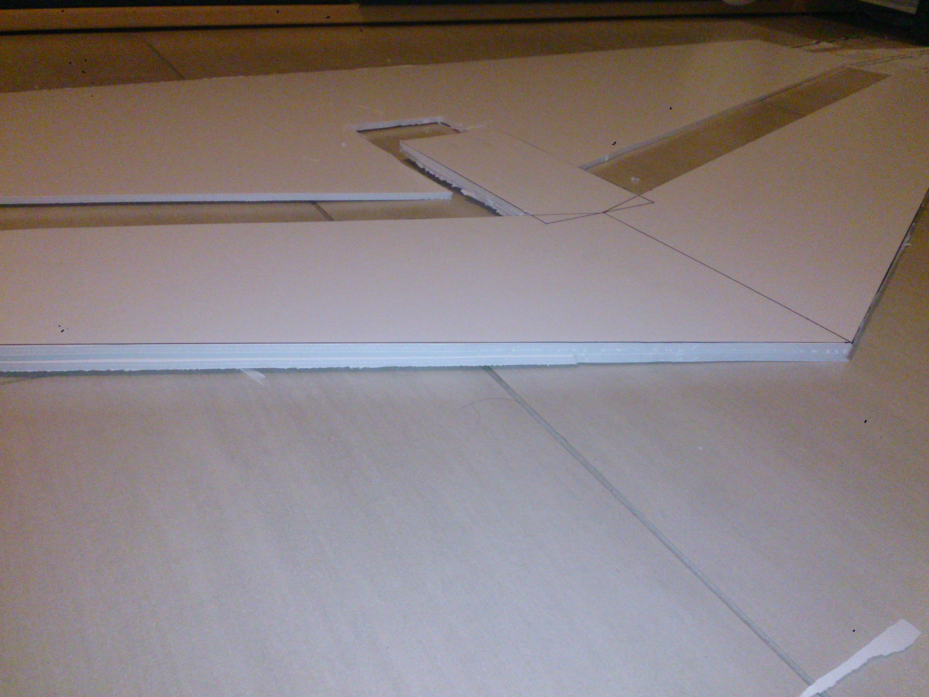
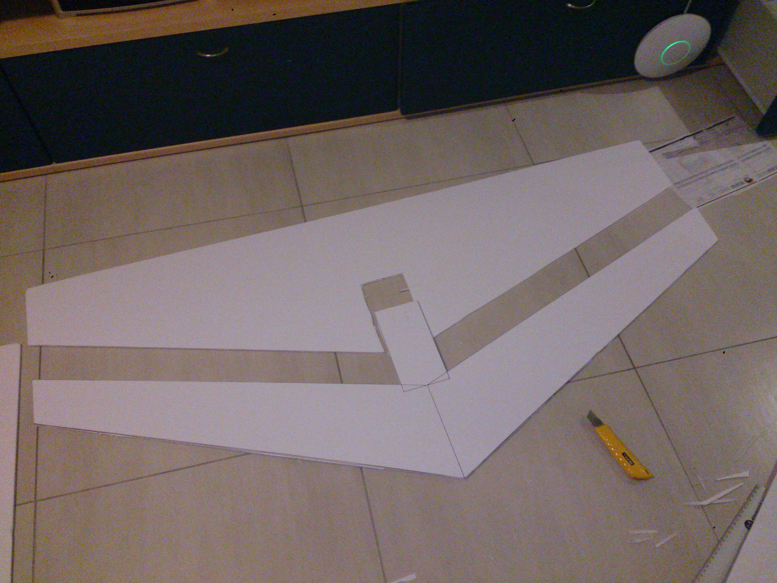
Wing span 1520mm Sweep Angle 25 degrees Root Chord 400mm Tip Chord 200mm Airfoil KFm2 The wing span was chosen simply because that's the largest size of foam I can easily obtain, and the root chord and tip chord were chosen to be in a 2 : 1 ratio. The "airfoil" will be a KFm2, which is extremely easy to build, and apparently gives decent performance. Essentially it is just a stepped airfoil, with a single step on the top at 50% of the chord.
Both the FPV49v2, from FPVTrond and the Raptor 140, by MyGeekShow served as the primary inspiration. This design will have the same airfoil and motor mounting style as the FPV, while keeping the elevon style from the Raptor.
So far I've cut out the upper half of the KFm2 step. Hopefully I'll be able to finish assembling this soon and test it out, then get some proper build instructions up - as well as few videos of me crashing it into the ground :)
![]()
![]()
-
Getting the autopilot to co-operate
05/04/2014 at 18:29 • 0 commentsI could just have gone and bought a complete APM system, but at a few hundred dollars, plus expensive shipping, I decided to go for a decidedly more budget route for the first autopilot system.
Take a Cheap Arduino clone and add a Chinese 10-DOF board, and you get a cheap (~$50 total) platform that can run the ArduPilot code. Well, sorta. While the BMP085 and HMC5883L on the sensor board were both well supported, the IMU - a MPU6050 was not. At first glance I thought it was, as the ArduPilot code has a driver for the MPU6000, with the difference being that it drives the 6000 in SPI mode whereas the 6050 is I2C only.
I contemplated writing an I2C driver for the chip - but some searching revealed that this had already been taken care of. The MegaPirateNG project has extended the ArduPilot code to support a greater variety of boards, including quite a few of the cheap HobbyKing ones. Once the code was compiled and loaded on to the board, it was time to hook up the sensors.
Or it would have been, if the Arduino clone ran off 3V3 or the sensors were 5V tolerant. Unfortunately neither of these are the case, and so getting it to work involved a bit of modification to the Arduino clone itself. In I2C, the bus is not driven high, instead pull-up resistors are used, and the bus is driven low.
This makes level shifting fairly easy, since you can just tie the pull-ups to the lowest voltage you need to support, and provided it is still higher than the threshold for a logic level 1, things will work. Usually the Arduinos use the AVR's built in pull-ups to do this, but for some reason the Arduino Mega has extra 10k pullup resistors. I cut the trace to these, and added in some external pull-ups to 3V3.
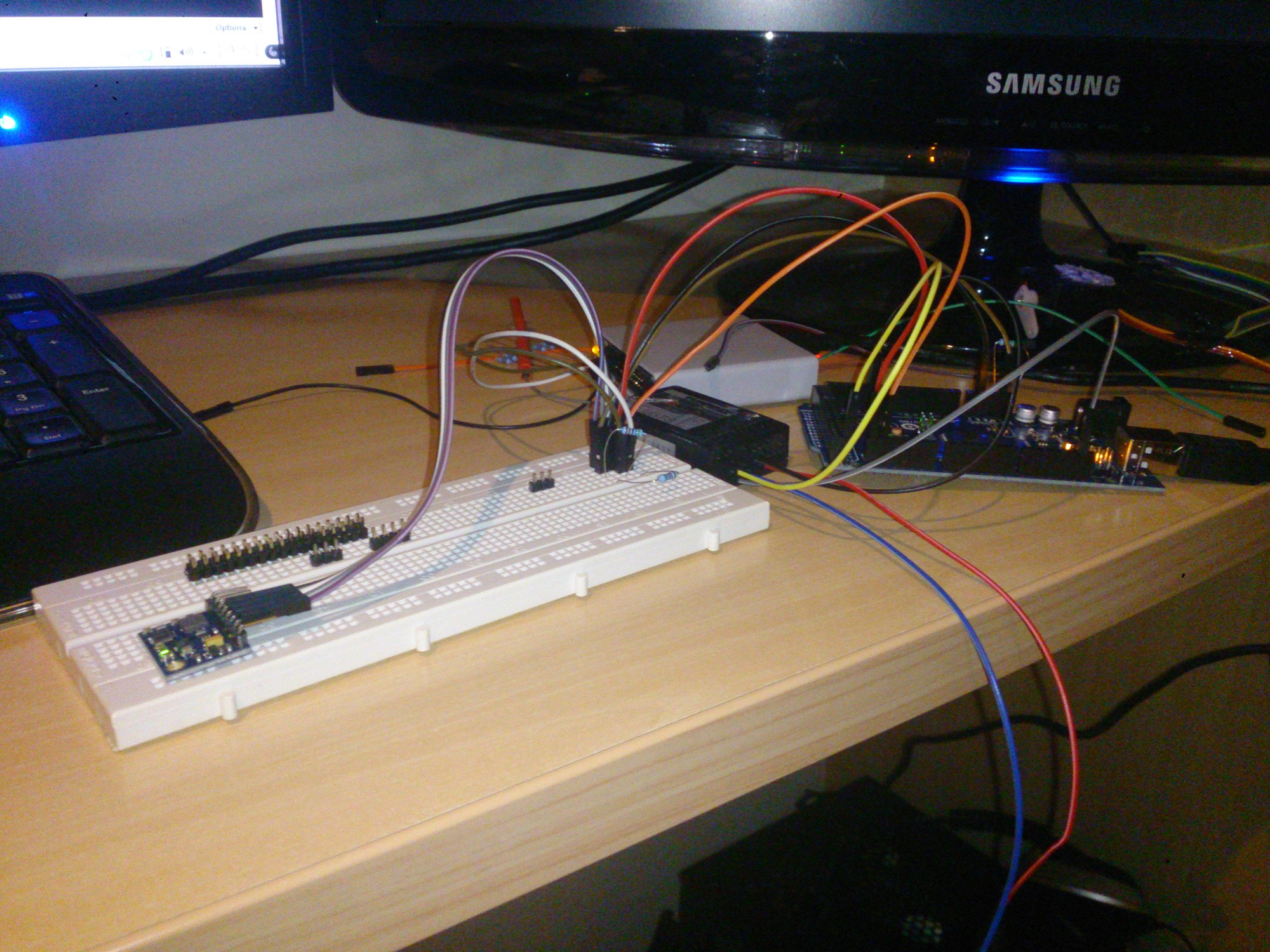
The rest was fairly straightforward. The channels from the radio receiver connect to the analogue input pins, and the PWM output pins are the output from the autopilot. It was a nice change not having to deal with and decipher a complicated pin mapping scheme, like on the Beaglebone Black or STM32s.
![]() Flying environments tend to be a bit inconducive towards breadboards, unfortunately.
Flying environments tend to be a bit inconducive towards breadboards, unfortunately. -
Hello World!
05/03/2014 at 09:47 • 0 commentsAbout time I put up a first post (or log, same thing). Unfortunately there's been a string of public holidays in South Africa and between those and work, I haven't had the chance to go and get the sheets of foam that form the base material for building the wing.
The current photo is an earlier wing I built, based off the FPV49 design. It uses a KFm-2 aerofoil which makes for really easy construction, and had been scaled down to around 1m instead of the original 1.25m. The planned design for the wing for this project will have a longer wingspan, be less swept back, and have a higher aspect ratio - essentially trying to make it more efficient at the expense of control and stability.
Not that this should be a problem for APM:Plane that will be doing most of the flying work. Over the next few days, I'll be playing around with the autopilot system, hopefully getting everything up and running. One of the downsides about living in South Africa is the extremely long shipping times, so instead of buying a ready made APM board, I got myself an Arduino Mega 2560 clone, and a 10-DOF sensor board.
![]()
Photo unrelated, it's a shot I took from up on Table Mountain.
Swarm
A flying, distributed wireless mesh network. What could possibly go wrong?
 Flying environments tend to be a bit inconducive towards breadboards, unfortunately.