Alvaro Villoslada
-
Hackaday Prize Finals, here we go!
10/09/2016 at 22:29 • 2 commentsAfter spending the last few weeks working really hard to get everything ready for the finals, it is finally all over. I have just posted the video for the finals, every file needed to replicate Dextra is uploaded and the assembly instructions are updated. It has been quite an experience, and the whole HAD prize thing has helped to give a huge boost to the project.
I want to give my most sincere thanks to Hackaday for giving hackers and makers around the world this great opportunity to show people what we can do, and to demonstrate the tremendous power and potential that the open source philosophy and the community have.
And finally, I want to wish all my fellow semifinalists the best of luck. The die is cast!
-
The cost of Dextra
10/08/2016 at 20:02 • 0 commentsOne of the things that I still had to do was to calculate the total cost of Dextra. As I say in the project description, Dextra is a low-cost robotic prosthesis, but how low?
Component Pcs Unit price Subtotal Pololu Micro Metal Gearmotor 1000:1 HP with extended motor shaft 5 $23,95 $119,75 DRV8838 Single Brushed DC Motor Driver Carrier 5 $2,99 $14,95 Pololu magnetic encoder for Micro Metal Germotors 3x packs of two pcs $8,95 $26,85 Turnigy TGY-EX5252MG Twin BB Digital Micro Servo 1 $9,73 $9,73 Teensy 3.1 1 $19,80 $19,80 PLA or ABS filament spool 750 g $21,60 $21,60 Fishing line spool (0.6 mm diameter) 1 $8,90 $8,90 1/8'' orthodontic elastic rubber bands Bag of 100 $5,49 $5,49 M3x14 bolt Bag of 50 $6,25 $6,25 M3x12 bolt Bag of 50 $7,53 $7,53 M3x8 bolt Bag of 50 $6,92 $6,92 M3x6 bolt Bag of 50 $5,42 $5,42 M3x12 spacer 2 $0,471 $0,942 M3 nut Bag of 100 $5,26 $5,26 Total cost $259,392 So the total cost of building a Dextra hand is $260. Of course, the "per unit" cost is less than this price, because for some components you have to buy more than what is needed to assemble the hand. For example, the total amount of plastic to print the mechanical components of the hand is 142 g (with 20% infill in all the pieces), so the unit cost of the plastic would be a little more than $4. The same happens with the screws, that come in bags of 50 units. When calculating the cost for the unit prices of each component and for the necessary quantities of each one, the price of building a Dextra hand drops to $197.3342. Pretty affordable I think!
-
Reproducing the Cutkosky grasp taxonomy
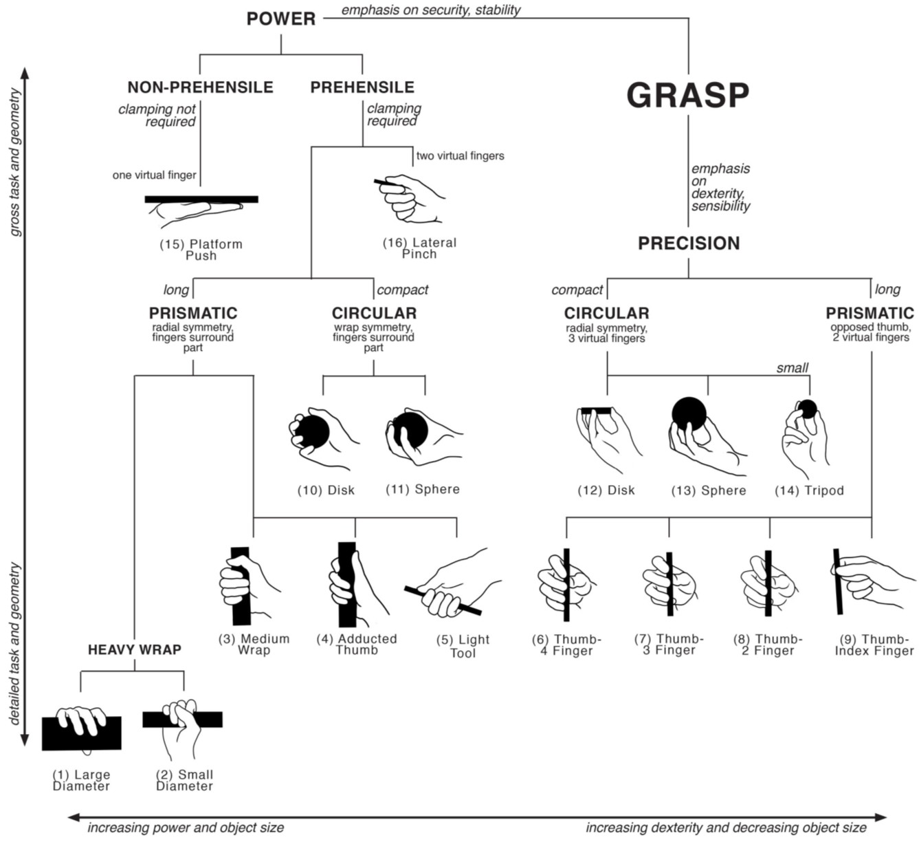
10/06/2016 at 12:29 • 0 commentsWhen robotic hand designers want to evaluate the dexterity of their latest design, the most common method is to try to reproduce as many grasps as possible from the Cutkosky grasp taxonomy. Mark Cutkosky wrote a paper in 1989 where he classified a set of manufacturing grasps in order to evaluate analytical models of grasping and manipulation with robotic hands. Since then, this taxonomy has been widely used to test the dexterity of robotic hands, to the point of becoming one of the basic benchmarks for these devices. This is the hierarchical tree of grasps:
![]()
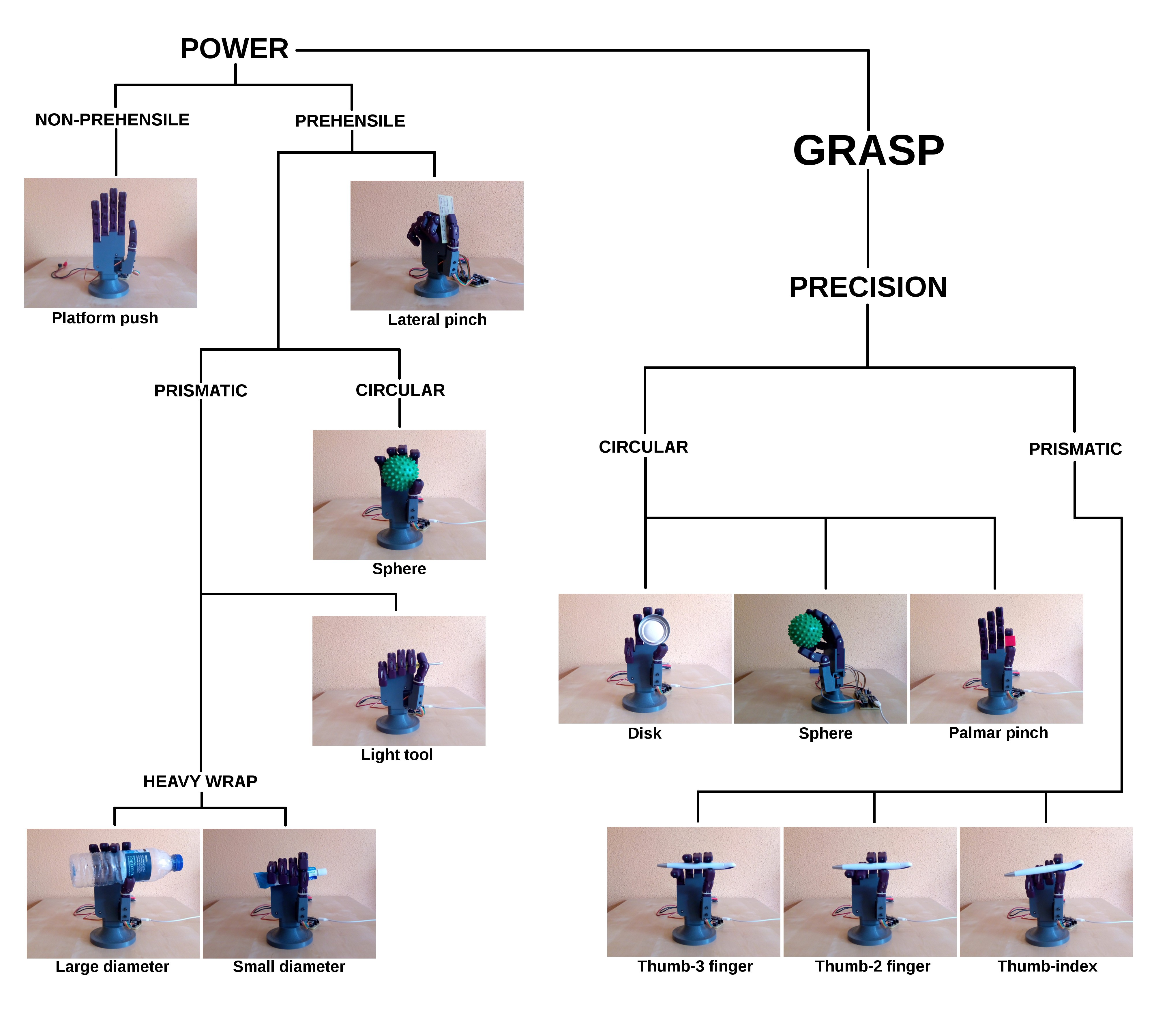
In the next image, this hierarchical tree is reproduced with images of Dextra performing the same grasps identified by Cutkosky:
![]()
As can be seen, Dextra is able to reproduce 12 of the 16 Cutkosky grasps. To put this in perspective, the Robonaut 2 hand is able to reproduce 15 of the 16 grasps. I think it is not bad at all that a robotic hand that can be built at home is able to perform just 3 grasps less than a robotic hand designed by NASA.
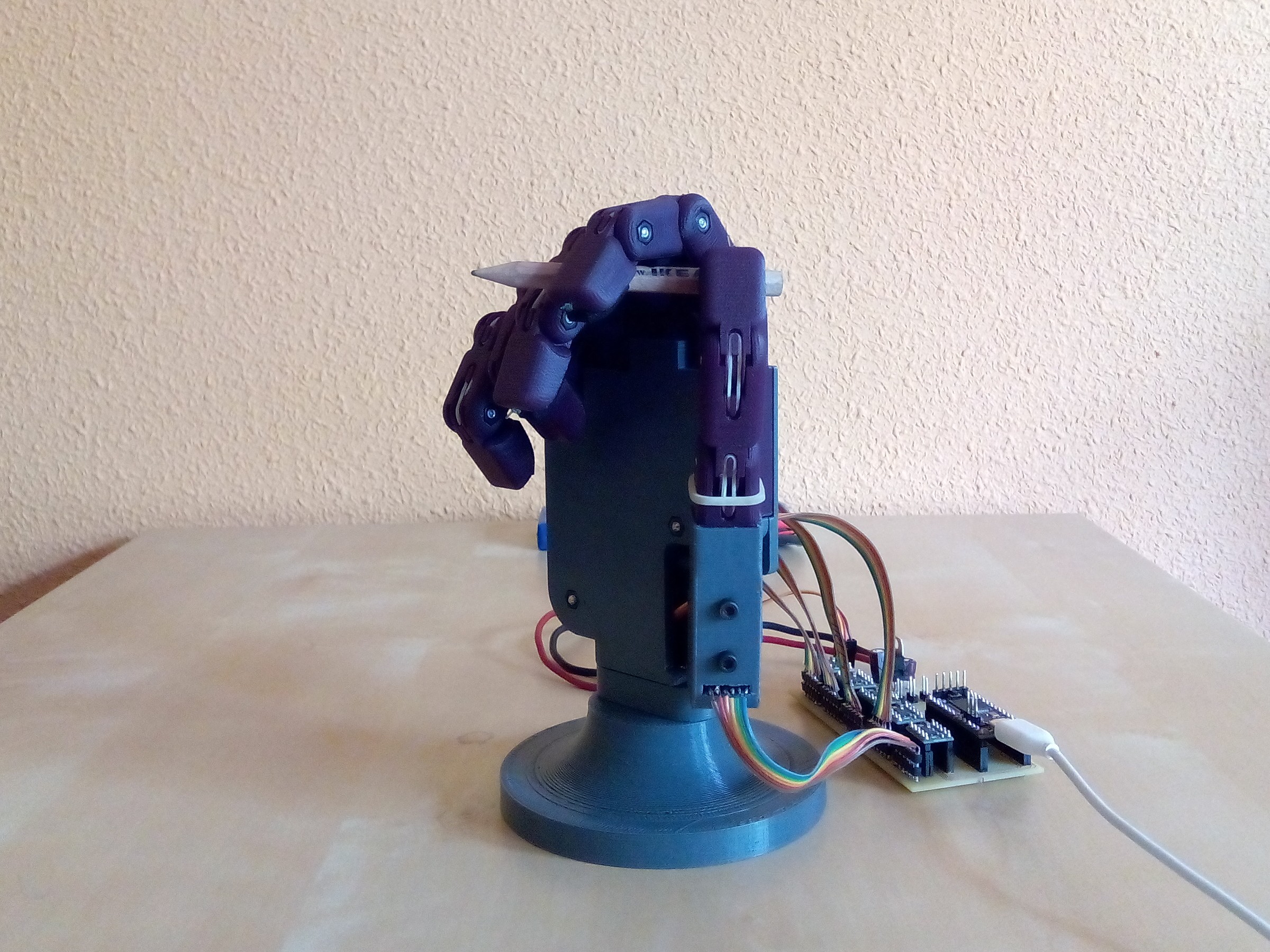
The robotic hand is also able to reproduce some grasps that are not present in the original grasp taxonomy. Cutkosky admits in his paper that the taxonomy is incomplete, because there are grasps, that he considers as "children", or combinations, of the classified grasps, that are not included. One of these children grasps is the one we use to write with a pencil. In view of the great obtained results, why not test whether Dextra is also able to perform this kind of grasp?
And indeed it can! Of course to do this, I have helped the hand a little bit to put the pencil between the fingers. But once grasped, Dextra grabs the pencil very firmly and, thanks to the anti-slip pads of the fingers, it stays in place. I have to admit that I did not expect such good results at all.![]()
-
Anti-slip fingerprints
10/05/2016 at 09:21 • 0 commentsOne of the things that have been on the drawing board for some time is the improvement of the stability of the grips. PLA, which is the material of which Dextra is made, does not have very good anti-slip properties. For this reason, when handling small or thin objects the grip was not very stable and they always fell, and so did moderately heavy objects, such as a filled bottle, held upright.
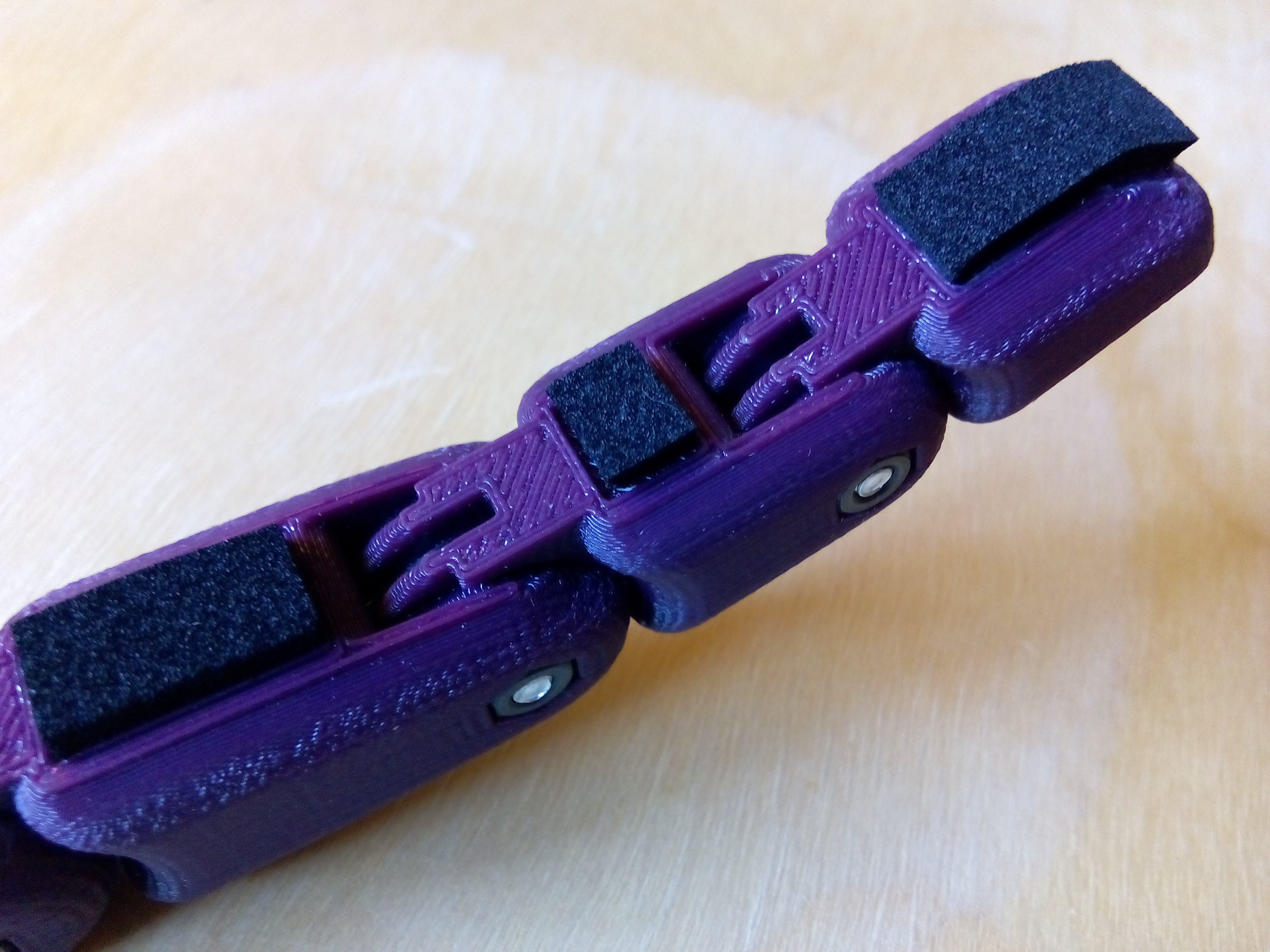
When I designed the current version of Dextra, I took into account this problem, so I included a small rectangular cavity on the underside of each phalanx. My idea was to fill these cavities with some material with a high friction coefficient and that was cheap and easy to get. However, after finishing the mechanical design, I started working on the software and other aspects of the project and I put aside the issue of grasp stability.
This week I decided to tackle this problem, to be able to reproduce the Cutkosky grasp taxonomy (which is the most used benchmark for robotic hands) for the video of the Hackaday Prize finals. First, I tried with bathroom silicone sealant, but it was more slippery than I thought. I also thought of using laptop rubber feet, cut to fit inside the cavities of the phalanges, but they are usually quite bulging. Some years ago I used hot-melt adhesive for a similar purpose, so yesterday I went to the nearest hardware store to buy a hot glue gun and some glue sticks. I love hardware stores, so I took a walk to see what products they had. Then, on a shelf, I found a much better solution: a 9x10 cm rectangle of self-adhesive anti-slip foam. It is simply perfect. It is not only cheap (about $1,5 the unit) and easy to get, but also it is much better than hot-melt adhesive or laptop rubber feet because it is much softer. This means that when grasping an object, the pads will adapt to its surface, which will allow to perform much firmer grips, and even (a must try) hold delicate objects like an egg. In addition to that, being self-adhesive, its integration is a piece of cake.
Today I have cut the pads with the dimensions of each of the cavities and installed them on the fingers. The result can be seen in the image below. I have spent the rest of the morning reproducing almost all of the grasps from the Cutkosky grasp taxonomy, and I am really happy with how the new anti-slip "fingerprints" work. Tomorrow I will post a new log showing the results of the grasping experiments, because I am frankly surprised by the dexterity of the hand, even though I am its designer!
![]()
-
First force control tests
10/03/2016 at 15:25 • 1 commentAs I said in the project details, I think a position controller alone is not enough to have a fully functional robotic hand. With only a position controller, to grasp any object without breaking it (or without risking damaging the hand), the approximate finger positions to grasp that object must be known beforehand. For example, to grasp a bottle, the hand must roughly know what are the positions of each finger to grasp that particular bottle. To grasp a ball, a different set of positions is needed, and so on for any other object. Thanks to the underactuation mechanism used in the mechanical design of Dextra, the exact positions are not needed, since the fingers can adapt to the shape of the grasped object. But it is obvious that it is not practical to have a preprogrammed set of grasps, because this set can be enormous and the task of programming each one can be very time consuming.
For me, the solution to this problem is to use a force controller. In fact, I think the ideal solution would be to use a hybrid position-force controller. With the position controller, the fingers could be configured to adopt a preconfigured pose from a small set consisting of the main hand grasp types (in the robotics field this is known as pregrasping). From this pregrasp pose, the fingers would be commanded to close, and the final grasp would be controlled by the force controller. Thanks to the adaptive grip, the fingers would conform to the shape of the grasped object.
But before working on hybrid controllers, I have to implement a force controller. The first question one asks when developing a closed-loop controller is, how do I measure the variable I want to control? In this case, where I want to control the force exerted by the fingers, the first answer that came to my mind was: force sensing resistors. FSRs are small and have a low profile, so its integration would not increase the volume of the robotic fingers, they are very easy to use (they are variable resistors) and they are moderately priced. The question is, how many sensors would each finger need? Just one on the fingertip? One per phalanx? Ideally, the best option is the second one, but this would increase the cost and complexity of the system. But even if only one sensor on the fingertip is used, there is another problem: wiring. Having sensors on the fingers implies wiring them up to the micrcontroller. Integrating cables into an articulated mechanism such as a finger has a certain complexity, but for me the biggest problem is that the assembly of the hand would be more complicated. And one of the main objectives of this project is precisely that the hand has to be easy to assemble.
A while ago, a pair of colleagues from my university implemented a zero-gravity compensator for the arms of a humanoid robot. To measure the torque exerted by the motors, instead of using a force sensor, they modeled the motors and used their current consumption to get a torque estimation. I decided that this is a very suitable method for this project, because a single sensor can measure the total force exerted by one finger, and the sensors can be integrated into the control board along with the microcontroller and the rest of the components, without using wires.
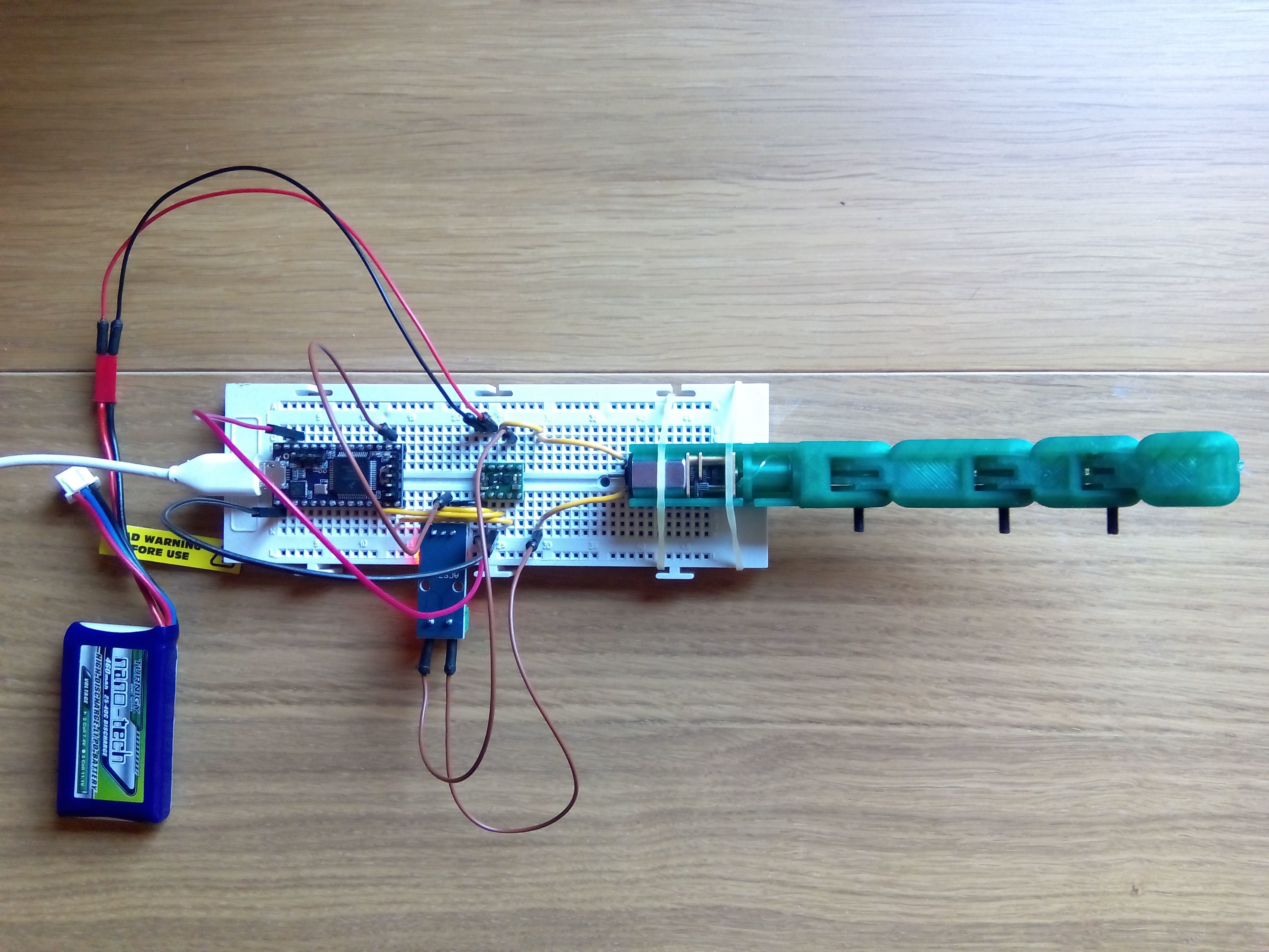
To begin testing this idea, I bought a Hall effect current sensor, the ACS712 (the model that measures up to 5 A). I printed and assembled a new finger module without soldering an encoder to the DC motor, since the feedback for the control loop is provided by the current sensor. With all the necessary elements, today I have set up the following test bench.
![]() I have decided to use a PID for the force controller, just like I have done with the position controller, so to get things moving I only have had to adapt the control code of the Dextra firmware. The results of the first force control tests can be seen in the video below.
I have decided to use a PID for the force controller, just like I have done with the position controller, so to get things moving I only have had to adapt the control code of the Dextra firmware. The results of the first force control tests can be seen in the video below. For a proof of concept, the results are not bad at all! I have had a couple of problems related to the current sensor. First, the measuring range of 5 A is too large for the current drawn by the motors of the hand, which reach a maximum of 1.6 A stalled. This means that with a proper sensor, the current could be measured more accurately. The second problem has to do with the noise of the sensors. The ACS712 is very noisy. This can be somehow fixed by soldering an extra capacitor at the output, but this week (the final week of the Hackaday Prize!!) my soldering iron has decided to stop working. I have managed to reduce this problem by filtering the noise applying a running moving average to the sensor measurements, but this introduces some delay between the real measurement and the filtered one. All of this makes me think that what I need is to design my own current sensor tailored to the needs of the project, but that will have to wait a little bit.
-
Myoelectric control system for Dextra
10/02/2016 at 19:16 • 0 commentsToday I have been working on the integration of the EMG control (using Mumai) with the latest version of Dextra. EMG control was already implemented in the first Dextra prototype, but it was not yet implemented in the current version of Dextra, the one that can be found here on hackaday.io and on its repo. In the following video, a demonstration of the implemented myoelectric control is shown.
Developing version 1.0 of Dextra has been a lot of work (and there are still things that I would like to implement). Besides greatly modifying the mechanical design, a lot has been developed on the software side: a new firmware that includes closed-loop control, a serial communication protocol made from scratch, the control GUI... All this work delayed me on the integration of the EMG control, and it was something that had to be done as soon as possible, considering that the project started as an attempt to develop an open-source and low-cost myoelectric prosthesis. However, I could not implement the EMG control before finishing at least the new firmware and the communication protocol, since controlling the hand depends on how it works and how it receives the motion commands.
So, how does the implemented myoelectric control system (MCS) work? First of all, the MCS runs on a separate microcontroller, not in the Teensy that runs the Dextra firmware. In the first Dextra prototype, both the hand controller and the MCS ran on the same microcontroller. But as I mentioned on the previous project log, the new firmware is quite more complex, with a bunch of interrupts firing here and there, so adding a MCS to the equation would probably make something not work properly, mainly because the EMG signal sampling also depends on a timer interrupt. Currently, the MCS is implemented on an Arduino Nano.
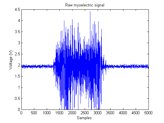
EMG data is acquired with one Mumai circuit from the flexor digitorum profundus muscle on the forearm, which is in charge of flexing the fingers. The output of the EMG circuit is connected to one of the analog inputs of the Arduino to digitize it. The EMG signal bandwidth goes from 20 Hz to 500 Hz, so it has to be sampled at least at a 1 KHz rate. To this end, a function that reads the analog input is set to run every 1 ms using the MsTimer2 library. With this simple configuration, the raw EMG signal is acquired.
![]() The simplest form of EMG control, and the easiest to implement in a microcontroller, is the threshold-based MCS. These controllers compare the amplitude of the EMG signals with a predefined threshold. If the amplitude exceeds the threshold, a hand close command is generated, and if not exceeded, a hand open command is generated. However, a raw EMG signal, like the one in the image above, cannot be used in a threshold-based MCS; it has to be processed. This is why most "hacker-friendly" EMG circuits output only the amplitude of the signals, doing the signal processing (rectification and smoothing) on the hardware side, so they cannot be used to acquire raw EMG signals (which is quite useful depending on the application). For this reason, I designed a circuit that outputs the raw signals for a more general use, with which the signal processing is done on the software side.
The simplest form of EMG control, and the easiest to implement in a microcontroller, is the threshold-based MCS. These controllers compare the amplitude of the EMG signals with a predefined threshold. If the amplitude exceeds the threshold, a hand close command is generated, and if not exceeded, a hand open command is generated. However, a raw EMG signal, like the one in the image above, cannot be used in a threshold-based MCS; it has to be processed. This is why most "hacker-friendly" EMG circuits output only the amplitude of the signals, doing the signal processing (rectification and smoothing) on the hardware side, so they cannot be used to acquire raw EMG signals (which is quite useful depending on the application). For this reason, I designed a circuit that outputs the raw signals for a more general use, with which the signal processing is done on the software side.As the EMG circuit is powered with a 0-5 V supply voltage, the EMG signal is centered around 2 V, to measure the full range of the signal. In order to rectify the signal, first its baseline voltage has to be lowered to 0 V. On power-up, the first calibration step of the MCS, the zero level setting, is in charge of that. In this first mode, the user has his muscles at rest for 30 s. During this period of time the EMG signal is measured. With the muscles at rest, the acquired signal is just the baseline voltage. After this time, the average of the measured signal is calculated. The resulting value is subtracted for now on from all the values converted by the ADC, so that all new measurements are centered around 0 V.
![]() Now, rectifying the signal is just a matter of applying the abs() function to any new measurements.
Now, rectifying the signal is just a matter of applying the abs() function to any new measurements.![]() The rectified signal is still not suitable to be used in a threshold-based MCS. In order to compare it with the activation threshold, the signal must be smoothed to obtain a measure of its amplitude. This smoothing is performed computing the moving average of the incoming rectified signals. Specifically, the technique used to calculate the moving average is the so called running moving average, which works by subtracting out the mean each time, and adding in a new point. The great advantage of this method is that it does not require any storage of previous data values, and minimizes divisions which are computationally intensive. This makes it very suitable for its use in microcontrollers with low RAM and low CPU speed, as the one used in Arduino.
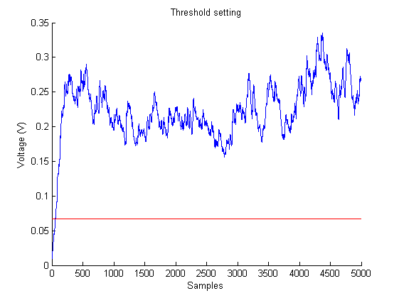
The rectified signal is still not suitable to be used in a threshold-based MCS. In order to compare it with the activation threshold, the signal must be smoothed to obtain a measure of its amplitude. This smoothing is performed computing the moving average of the incoming rectified signals. Specifically, the technique used to calculate the moving average is the so called running moving average, which works by subtracting out the mean each time, and adding in a new point. The great advantage of this method is that it does not require any storage of previous data values, and minimizes divisions which are computationally intensive. This makes it very suitable for its use in microcontrollers with low RAM and low CPU speed, as the one used in Arduino.![]() The last step before being able to control the robotic hand is to set the activation threshold. This setting is done during the second calibration step, after measuring the baseline voltage. In this step, the user makes a strong muscle contraction for a period of 5 s. This contraction must not be as strong as to be tiring and uncomfortable for the user. During this 5 s period, the maximum value of the smoothed EMG signal is calculated. This value is the so called maximum voluntary contraction, or MVC. From the MVC, a relationship is established between its value and the activation threshold. The value of the activation threshold is the 20% of the measured MVC.
The last step before being able to control the robotic hand is to set the activation threshold. This setting is done during the second calibration step, after measuring the baseline voltage. In this step, the user makes a strong muscle contraction for a period of 5 s. This contraction must not be as strong as to be tiring and uncomfortable for the user. During this 5 s period, the maximum value of the smoothed EMG signal is calculated. This value is the so called maximum voluntary contraction, or MVC. From the MVC, a relationship is established between its value and the activation threshold. The value of the activation threshold is the 20% of the measured MVC.This mode is a very important feature of the implemented MCS. When one has been using a prosthesis during some time along the day, the EMG signal amplitude starts decreasing and the MCS starts failing. This is due to muscle fatigue: the more tired the muscle is, the smaller the EMG signal. If the activation threshold has a fixed value, the EMG signal amplitude may not reach its activation value. However, if a variable threshold is used, it can be adjusted to the muscle contraction level. With this mode, the user can set the MVC value with which he feels comfortable at any time. This way, the activation threshold always has a value reachable by the EMG signal, no matter how tired the user is, and the MCS does not fail.
![]()
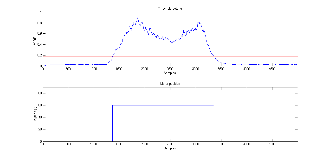
With all set, the robotic hand can now be controlled. During control mode, the EMG signal is sampled, rectified, and its moving average is calculated continuously, as explained before. Every time the MCS detects that the amplitude of the EMG signal is above the activation threshold, signaling a voluntary contraction, the finger positions corresponding to a closed hand position are sent to the hand microcontroller through the serial port, using the Synapse protocol. On the other hand, if the amplitude of the EMG signal is below the activation threshold, the finger positions corresponding to an opened hand position are sent.In the following video, it is shown how the implemented threshold-based EMG controller works.
![]() As with the rest of the elements of this project, the code that does everything described above is in the Dextra repository. It is not yet merged into the main branch, since I am still polishing some details, but it can be found in its corresponding development branch.
As with the rest of the elements of this project, the code that does everything described above is in the Dextra repository. It is not yet merged into the main branch, since I am still polishing some details, but it can be found in its corresponding development branch. -
Need for (microcontroller) speed
10/01/2016 at 17:43 • 0 commentsWhy did I chose a Teensy 3.1 as the "brains" of Dextra? At the beginning of the project, when the fingers were open-loop controlled, I used an Arduino Uno to send the motion commands to the motor drivers. Once I had the mechanical design of the hand more or less finished, I decided that it was time to start working on closing the control loop.
Since the fingers are underactuated, it didn't make much sense to put one angular sensor for each joint of the finger, as they cannot be independently controlled. So I thought that to close the control loop, I just needed to know the total linear displacement of the finger tendon. Instead of using a linear sensor, which would take a lot of space, I decided to measure the angular displacement (in radians) of the motor shaft with an encoder and transform this quantity into a linear displacement by multiplying it by the radius of the spool that winds and unwinds the tendon.
Pololu sells small quadrature magnetic encoders for their micro motors, that can be directly soldered to the motor power pins, so choosing the sensor was easy. After researching how quadrature encoders work, and how to implement them with an Arduino (I have never worked with encoders before), I realized that I needed a microcontroller with at least five external pin interrupts (a quadrature encoder can use one or two interrupts, depending on if you want to have half or full resolution). An Arduino Uno only has two pin interrupts, so I took an Arduino Mega I had lying around and started developing the control firmware.
After adjusting the PID gains and tweaking the code here and there, the first tests, where I moved only one finger at a time, went very well. But as soon as I started moving several fingers at the same time, the hand started to operate worse. After a few closing-opening cycles, some fingers closed more than commanded and others opened more than they should. To make an analogy with stepper motors, it was as if the motors were losing steps.
To better understand what was going on, I will explain how the finger controller works (it is very simple actually). Basically it consists of two elements: the encoder counter and the actual control function. Every time one of the encoders generates a pulse, a function that increments or decrements the number of encoder "ticks" is executed. This is the only thing that this function does, to reduce its computational cost so it runs as fast as possible. The conversion from the number of encoder "ticks" to the linear displacement of the tendon is done in the PID function. The five PID loops that control the five fingers of Dextra are executed sequentially, from the thumb to the little finger, every 10 ms inside a timer interrupt (using the fantastic MsTimer2 library).
So, what do we have here? A lot of interrupts. Being a timer interrupt, I know when the controller interrupt runs, but there is no way of knowing when the encoder interrupts are going to execute, or if they are blocking each other. Going back to the problem I had with the fingers not moving as they were commanded, I assumed that what was happening was that sometimes, for some fingers, the function that counts the pulses of the encoders was not executed. I thought this was happening because the speed of the microcontroller was not enough to run a counting function before the interrupt of another encoder was fired. My reasoning was as follows: if while the counting function of a finger is running the encoder of another finger triggers its interruption, the counting function of the second finger will not run because the counting function of the first finger is still running, and thus, the motor of the second finger will skip a pulse while it is moving, causing the finger to close or open more than it should.
With that reasoning in mind, I switched to a Teensy 3.1 which has enough pin interrupts for my purposes, runs at 72 MHz (96 MHz if overclocked) and is Arduino-compatible. After making some small changes to the code and connecting everything, I started a closing-opening cycle test. After half an hour running, the fingers were still closing and opening as commanded, so it seemed I was right and I simply needed more microcontroller speed.
-
Madrid Mini Maker Faire 2016
09/27/2016 at 14:33 • 0 commentsThis past weekend I've been at the Madrid Mini Maker Faire 2016 giving a talk about Dextra and showing it to the fair visitors. It was a lot of fun and it also served as a stress test for the hand; until now, it had not been running for such a long time. Thankfully everything worked as expected: the batteries had autonomy for the two days, the electronics worked flawlessly and no piece of the hand broke. So it seems that the design is quite robust, yay!
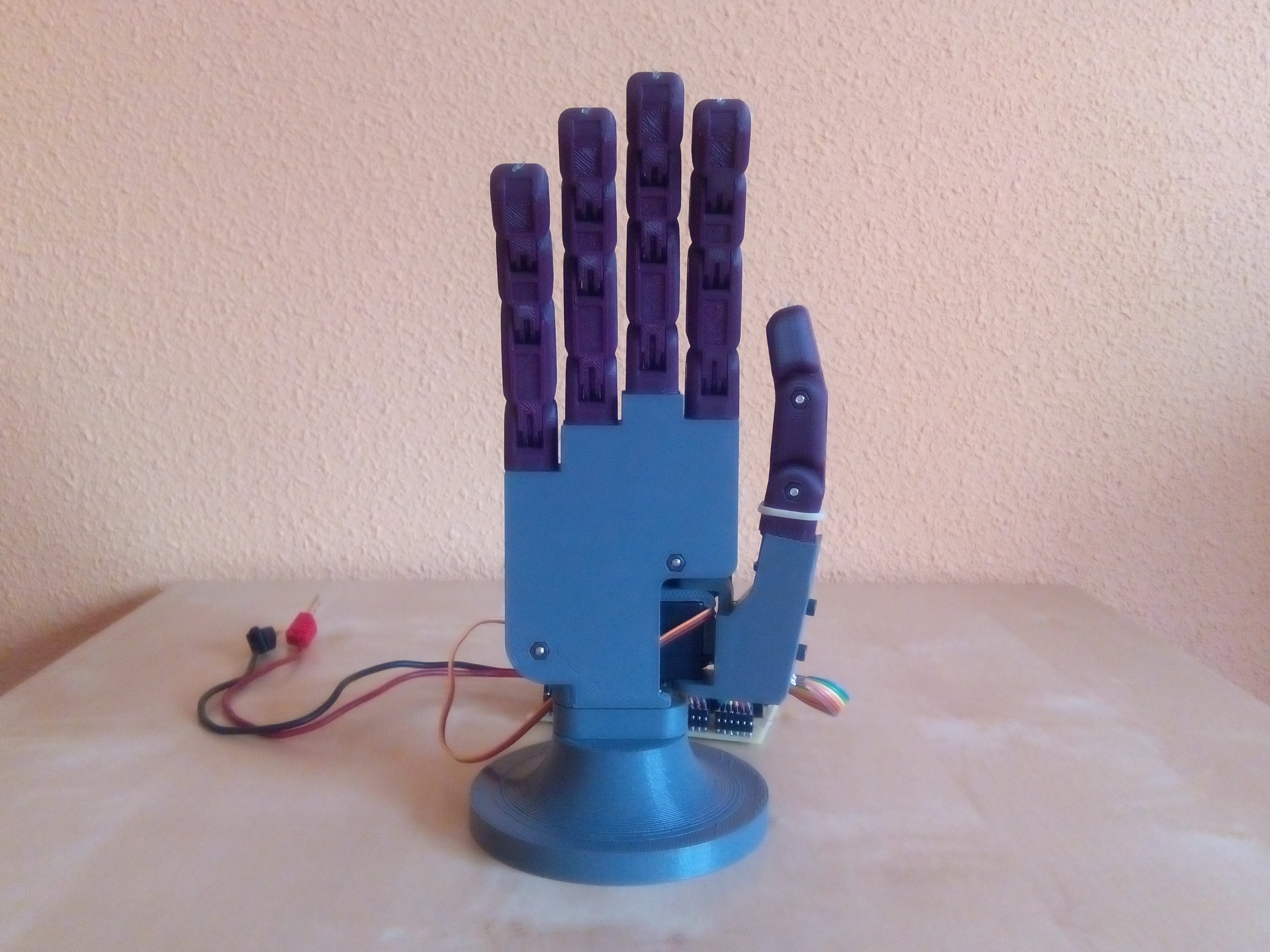
Last week I worked like crazy to have some new features ready for the fair. Among other things, the palm and the back of the hand have undergone a major redesign to integrate a wrist with an embedded M10 screw, to make it compatible with the International Committee for the Red Cross’s (ICRC) transradial prosthetics manufacturing guidelines. I also designed a base to allow putting the hand in a vertical position. Thanks to this, now I can do grasping experiments in a much convenient way, and it also looks much better than having the hand lying on the table.
![]() To show what Dextra is capable of, I programmed a bunch of Python scripts to execute different motions as well as to perform some basic grasps. I've updated the videos on the project details to show how the last version of Dextra works. Below, there is a video (in Spanish) I prepared to show the main features of Dextra during the Maker Faire.
To show what Dextra is capable of, I programmed a bunch of Python scripts to execute different motions as well as to perform some basic grasps. I've updated the videos on the project details to show how the last version of Dextra works. Below, there is a video (in Spanish) I prepared to show the main features of Dextra during the Maker Faire. -
Control board prototype
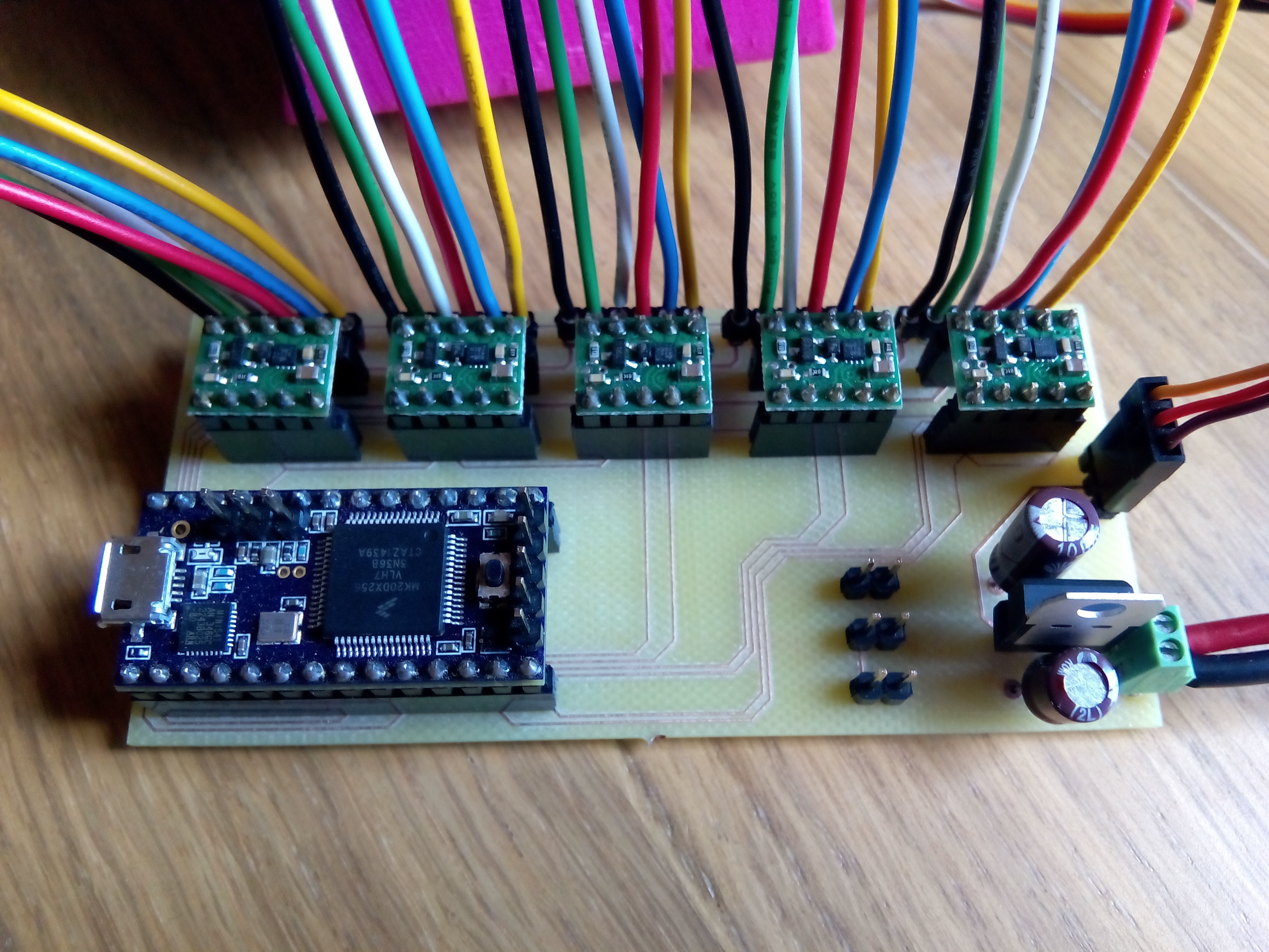
09/16/2016 at 17:58 • 0 comments![]()
This is the first prototype of the Dextra control board, which I've been testing today and works like a charm. Until now I have been working with all the components placed on a breadboard. The mess of wires was horrible, so I designed this very simple PCB containing a Teensy 3.1, the five DRV8838 motor drivers and a voltage regulator to lower the battery voltage to that required by the abduction servomotor. The Teensy board and the driver boards are inserted into a series of sockets to be able to replace the components in case something burns.
The next step in the electronic part of the project is to start working with the current sensors to implement a force controller for the hand. Also, thinking on an easy way of controlling the hand when used as a prosthesis, I'm planning to use an accelerometer to switch between different grip patterns by moving the hand in different directions. In this way, the user would change the grip pattern by just moving the hand in one direction, and the grip would be activated by just contracting one muscle, using only one EMG sensor. I will detail this idea in depth in one of the next project logs.
Once I have all this working, my plan is to integrate all these components in a control board that will be integrated inside the hand, with just three external connections: USB to program the hand, a connection for the EMG sensor (serial, SPI or I2C, I still have to decide) and the power connection (for a battery or a wall adapter power supply).
-
Development of the Dextra control GUI
09/14/2016 at 17:02 • 0 commentsAlthough this project focuses on its application as a prosthetic hand, Dextra is, after all, a robotic hand. By this I mean that it has no elements that make it specifically a prosthesis, so it can be used for other purposes. Especially, due to its open-source nature and the possibility of replicating it with a 3D printer, I think it has a great potential to be used in education and research.
When I studied my master in robotics, we had a Shadow robotic hand in our lab, but I could never get to use it, because it was too expensive to risk a student breaking it. Although I understand this fear, for me it was something really frustrating. So, why not use robotic hands that are low-cost and easy to repair to let frustrated students, researchers and makers get their hands on a real device to do real experiments rather than perform boring and unrealistic simulations? With all this in mind, I thought it would be interesting to provide other means of controlling Dextra besides the EMG interface that controls the hand when it is used as a prosthesis. So one of the things I've been working on lately is a simple and intuitive graphical interface to control Dextra from a computer.
It started as a simple Python script with which the desired positions could be sent to the hand microcontroller through the serial port one by one. This script was very useful for the first control tests and to check that the mechanics of the hand worked properly. It worked for me, but for a hypothetical future user it was too basic. Besides, the serial communication part could also be greatly improved, since each position was sent separately instead of sending all the positions at once in some kind of packaged format.
Building on that basic interface, I developed a serial communication protocol called Synapse (which in turn is based on a serial communication protocol called seCo, which I'm developing to send arrays of floating point numbers in an efficient way). The protocol sends the position of each finger and of the abductor in a floating point format converted to binary format, each value with an identifier (something like a hex address). All these values are packed in a message delimited by a header and a footer and with a checksum to check the integrity of the transmitted message. Furthermore, it is possible to send values from the microcontroller to the computer following the same message format, to allow retrieving information from the hand sensors. I've also developed a Python module to be able to use this protocol on the PC side.
But I still needed some kind of interface better than the original text interface. With no experience in designing GUIs, I needed something that was easy to learn and use, so I researched what are the options to design GUIs with Python (which is a great language to get things done quickly and easily, and with which I could integrate the communication protocol). I ended up using Kivy, which I found very appealing for being open-source and cross platform (it even runs on Android and iOS!). After a few days of learning and tinkering, I had a first version of the GUI finished.
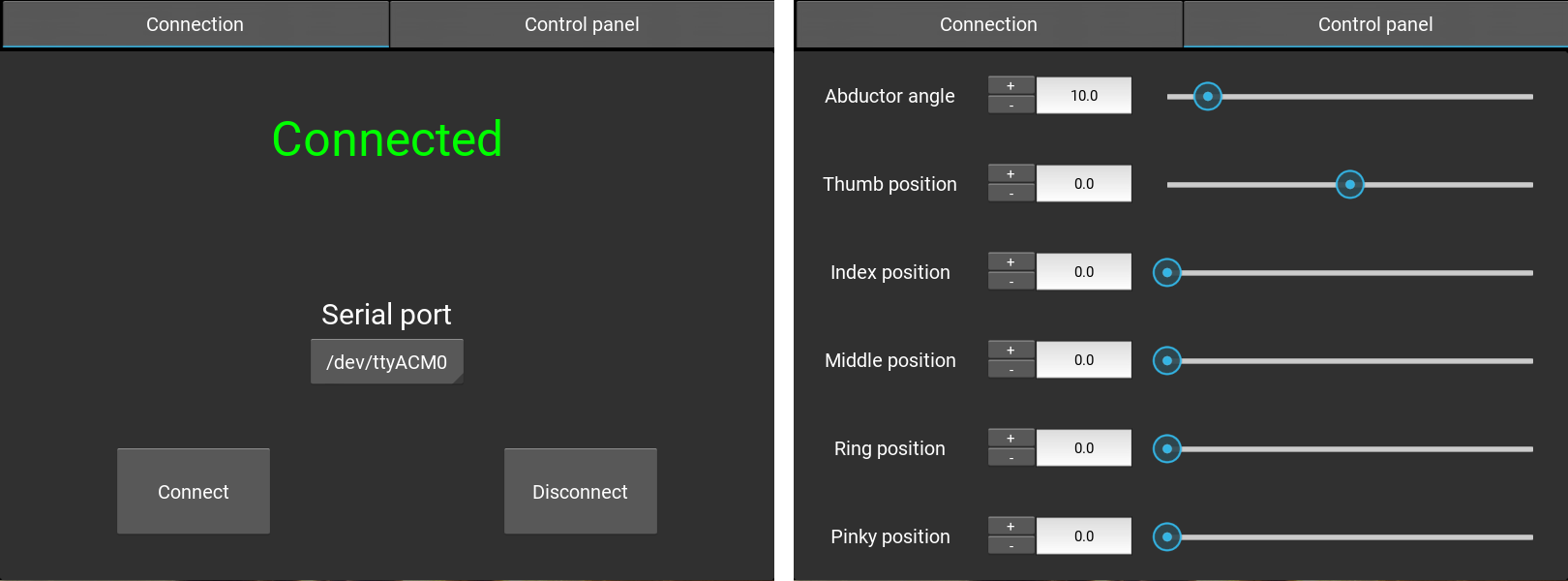
![]() The first tab manages the connection with the serial device running the Dextra firmware. The second tab is the one that allows controlling the fingers. This can be done either by entering the desired value directly into a text box, moving a slider, or through small increments with the buttons next to the text boxes to adjust the position accurately.
The first tab manages the connection with the serial device running the Dextra firmware. The second tab is the one that allows controlling the fingers. This can be done either by entering the desired value directly into a text box, moving a slider, or through small increments with the buttons next to the text boxes to adjust the position accurately.For the next version of the GUI, I'm planning to include a way of storing and reproducing different hand positions. In this way, it would be really easy to program the hand behaviour, and use these programmed gestures in different applications.
 The simplest form of EMG control, and the easiest to implement in a microcontroller, is the threshold-based MCS. These controllers compare the amplitude of the EMG signals with a predefined threshold. I
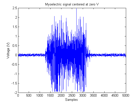 Now, rectifying the signal is just a matter of applying the abs() function to any new measurements.
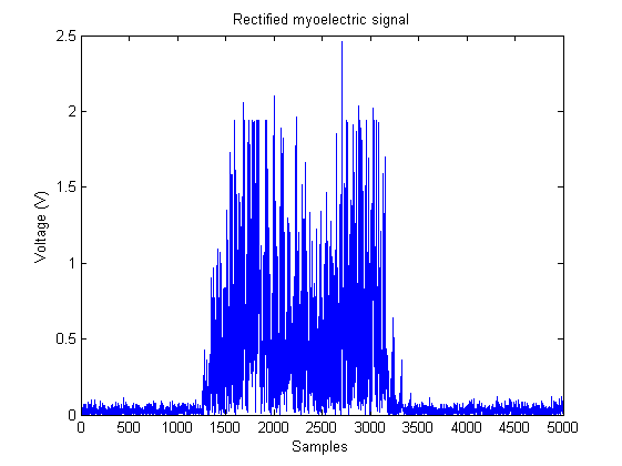 The rectified signal is still not suitable to be used in a threshold-based MCS.
 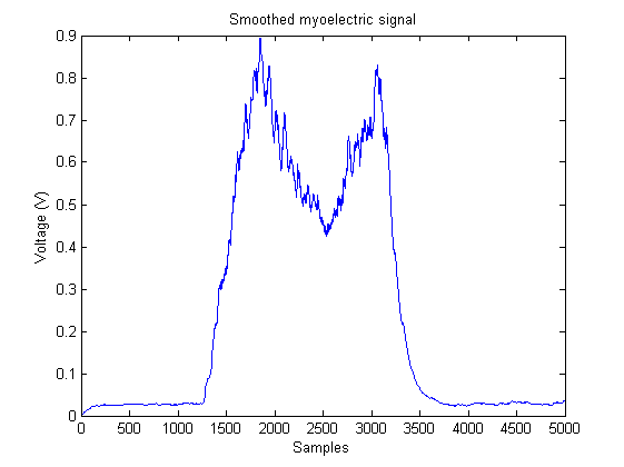 The last step before being able to control the robotic hand is to set the activation threshold. This setting is done during the second calibration step, after measuring the baseline voltage.