deʃhipu
-
Clock Stretching Woes
03/30/2016 at 19:39 • 2 commentsThe parts are still trickling in, but I'm waiting for the rest of the PCBs to start the mass-production of the workshop kits. Hopefully they will arrive tomorrow or Friday, so I can do it over the weekend.
Less good news is that the tracking number for the 200 servos that I ordered a week ago is not working (the seller gave me 4 different ones so far, none working). It's too late to order this from a different seller, and there is no brick-and-mortar shop that I know that has those. So it's possible that I will have only 10 complete kits, and 15 kits without legs. I'm still hoping that the servos will arrive on time, but there is nothing I can do with this. Frustrating.
Finally, on the software side, I made some progress debugging the I²C issues (after two evenings of analyzing the scope). I even found and tried a completely new slave library by Pololu, but decided to switch back to Wire.h for now (I might use that library later, especially since it has a workaround for the I²C bug in Raspberry Pi). Anyways, the issue seems to be that the Arduino slave is sometimes too slow for the 100kHz I²C, and the ESP8266 implementation doesn't support clock stretching, so it can't slow down when needed. The good part is that I found a way to compile a version of the firmware with slower I²C, so this shouldn't be a problem.
-
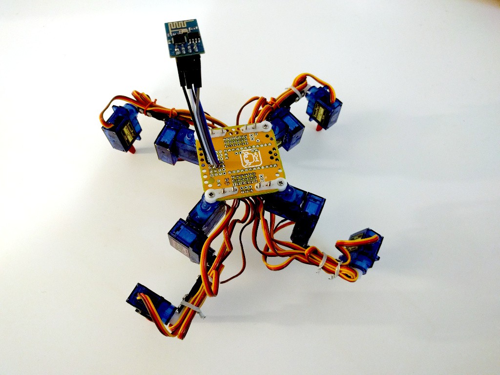
Walking with Python
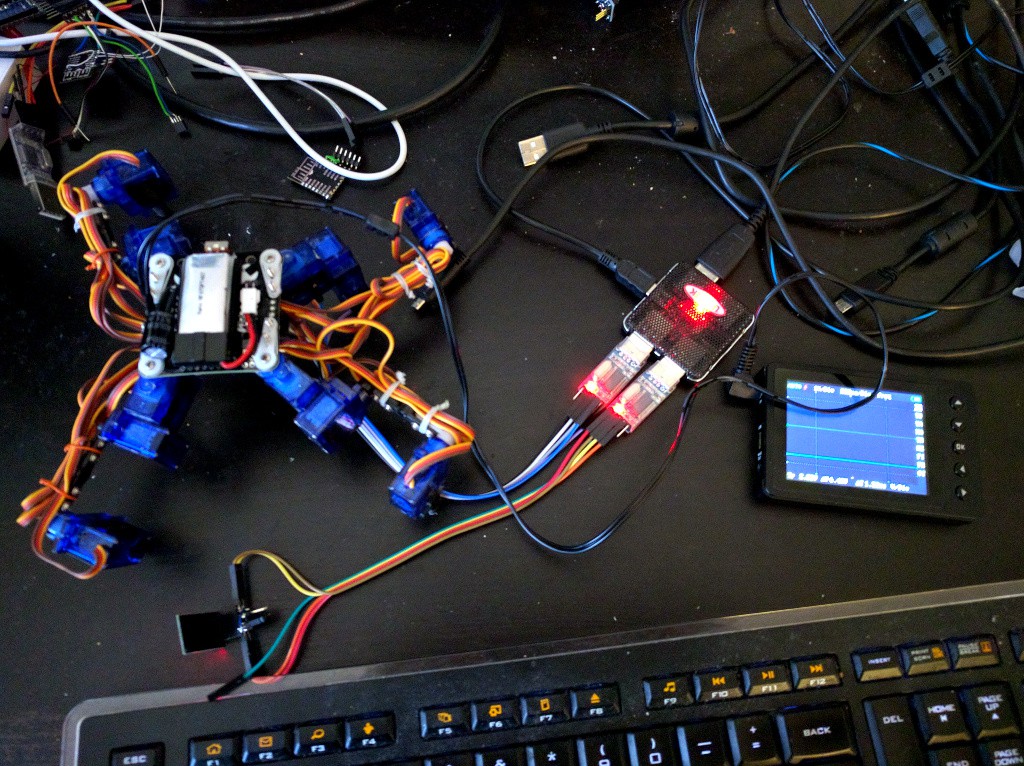
03/27/2016 at 20:31 • 0 commentsToday I finally sat down and wrote the Python part of the code for walking. Just the basic creep gait for now. I works, but there seems to be a problem with the I²C communication -- as I mentioned previously already, I'm getting OSError sometimes when sending the coordinates to the controller. It turns out that sometimes when that happens, the slave ends up stuck in a state where it won't listen to commands anymore, and has to be restarted.
![]()
I looked at the signals with a scope, and I'm pretty sure this is not due to noise on the line or inadequate pull-up resistors. I tried halving the resistors just to make sure, but of course no improvement. I suspect it's a race condition in the software I2C implementation on the ESP8266. Hopefully that will be fixed before the conference.
In the worst case, I will put all the gait code back on the Arduino and just use ESP8266 for remote control, but it would be so much better if you could program it with Python directly.
-
LiPo Chargers
03/26/2016 at 21:03 • 0 commentsThe conference is nearing, and I'm still waiting for the parts. I really hope that they will arrive on time. I'm not quite panicking yet, but soon I will probably start.
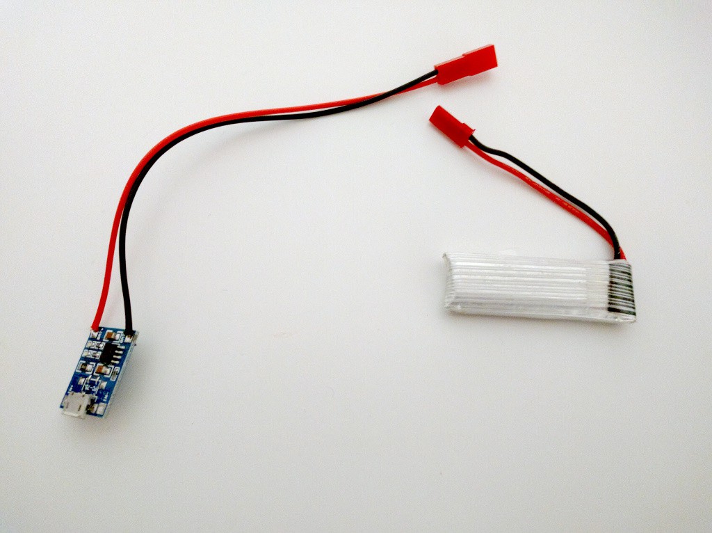
While waiting for the parts, I still need to write the remaining code for the ESP8266 (and possibly improve the code for the Arduino). Today I didn't even have enough concentration to do that, so instead I started soldering things. I still don't have all the parts to solder the PCBs, but I started with the LiPo chargers. The batteries I got have JST plugs on them, which easily plug into standard 2.54mm headers. But sooner or later someone will plug them in reverse, and if you do that with a cheap LiPo charger, you could have a fire. So I soldered proper JST sockets to all ten chargers (that's how many I have, as that was the initial count for the workshop, you will have to share).
![]()
I can already tell that soldering the remainder of the kits is going to be a full-time job. Hopefully the parts will arrive next week, so I have a weekend to do that.
-
Parts Trickling In
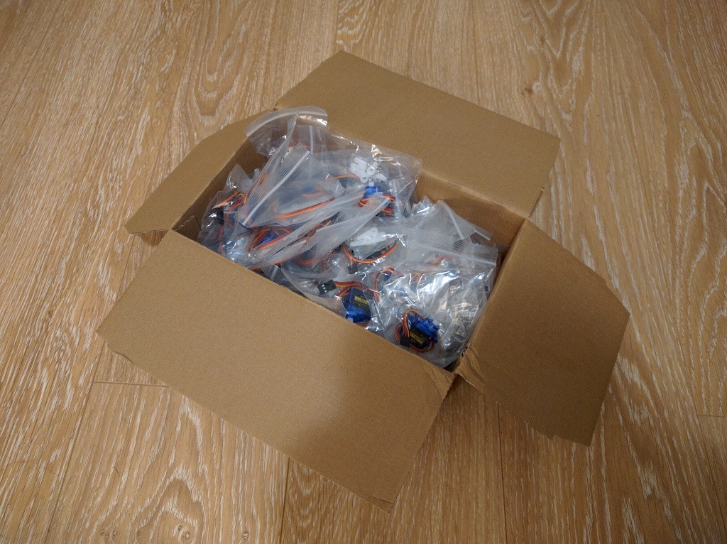
03/19/2016 at 22:57 • 0 commentsIt has been over three weeks since I ordered the parts for 10 kits, and they have started to trickle in slowly. I'm putting them all in one box for now. If you ever wondered how a box of 40 servos looks like:
![]()
One of the packages with 40 servos is held by customs -- they requested clarification of what it is and how much it costs, and since I've been traveling the whole last week, I will be only able to send it to them on Monday. One more package is still on the way -- with 12 servos per robot, ten kits makes 120 servos.
In the mean time I learned that in the end we will need 25 kits, so I quickly ordered additional parts, with some faster shipping. Fortunately they are cheaper in bulk, so that actually evens out the shipping costs. Next time I'm doing it, I'm going to order 300 servos instead of 120 -- due to the magic of bulk orders, the price is roughly the same.
Same goes for the printed circuit boards. At DirtyPCBs, whether you order 20 or 30 boards, the price is the same...
-
First Prototype
03/11/2016 at 18:07 • 0 commentsThe prototype unit is more or less ready. In the end I took the legs from one of my other Totes, so I have no step-by-step drawings. I will do rendered images instead -- they should be much cleaner and easier to follow then too.
![]()
On the software side, I have the Arduino code that does leg inverse kinematics pretty much ready (just need some trimming for the servos positions), and a basic Python code for the ESP8266:
from machine import I2C, Pin
import ustruct


class Robot:
    I2C_ADDRESS = 0x09

    def __init__(self):
        self.i2c = I2C(sda=Pin(0), scl=Pin(2))

    def leg_move_to(self, leg, x, y, z):
        data = ustruct.pack("Bbbbb", 4 * leg, 1, x, y, z)
        while True:
            try:
                self.i2c.writeto(self.I2C_ADDRESS, data)
            except OSError:
                pass
            else:
                break
This lets you move each of the legs to any position. So far so good. Next I will try to actually make it walk, but I doubt I will have any time for that in the following week, which is full of travelling for me.
-
Updated PCB
03/11/2016 at 10:29 • 0 commentsI fixed the PCB, and updated the link in the bill of materials to point to the new version. I also ordered the updated boards -- if they arrive before the workshop, we will use them. Otherwise there will be this additional jumper wire on all of them...
-
Mistakes and Workarounds
03/10/2016 at 20:26 • 0 commentsSo... the PCBs arrived, and they are mostly fine... Mostly.
Turns out that I somehow managed to delete the trace that connected the power supply to the servos on the left side with the power supply of the servos on the right side. Which means that servos on one side don't get any power. A quick soldering of a jumper wire solved the problem -- but I will have to do it for every of the 10 boards. Sigh.
But otherwise it all seems to be fine.
Oh, except for the battery placement. It will have to go on the top of the robot (obscuring the Jolly Wrencher logo), because the ESP8266 on the bottom takes too much space on the bottom.
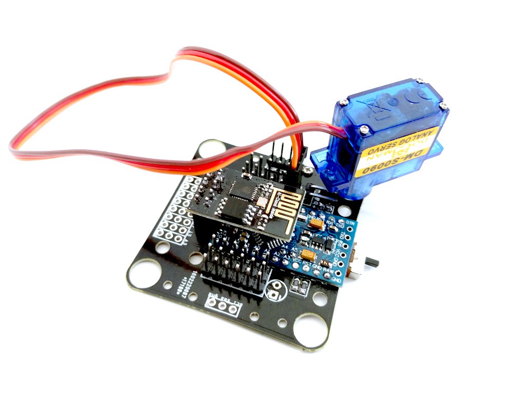
Here's the PCB with everything soldered to it and with one servo attached:
![]()
-
PCBs Arrived
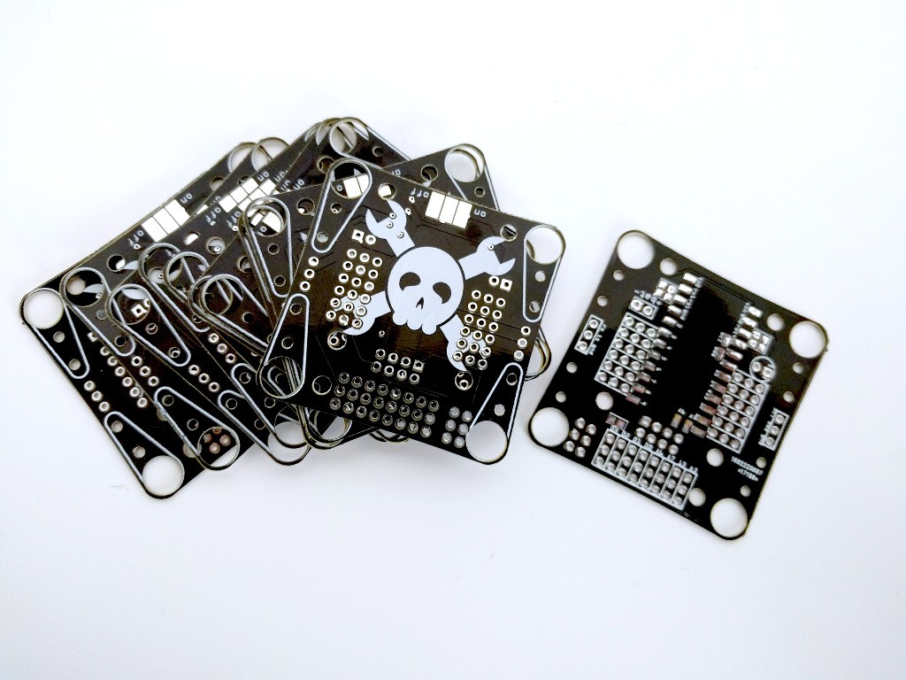
03/10/2016 at 09:35 • 0 commentsThe printed circuit boards for this version of Tote just arrived! I will build a prototype with one of them later and test it, but so far they look good:
![]()
-
Prototyping and Controller Code
03/06/2016 at 19:42 • 0 commentsWith the addition of ESP8266, Tote will now have two processors on board, and it makes sense to split the responsibilities for them a little bit. The ATmega328p on the Pro Mini is relatively slow (8Mhz) and weak, but has a lot of inputs and outputs, which makes it perfect as the servo controller, and generally as the spinal cord of the robot, controlling low-level reflexes. The ESP8266 is much stronger and faster (it has to be to handle WiFi), and so it could handle higher-level functions.
Because the time is precious, I started to work on the code for the Pro Mini already. I made a prototype using one of the older boards, but with the new leg configuration, and with some cables for connecting the ESP8266 to it:
![]()
Now I'm copy-pasting bits and pieces of the original Tote code, and adding some I²C communication on top of that. Basically, the ESP8266 will be sending coordinates for the legs to the Pro Mini, and it will handle leg inverse kinematics.
-
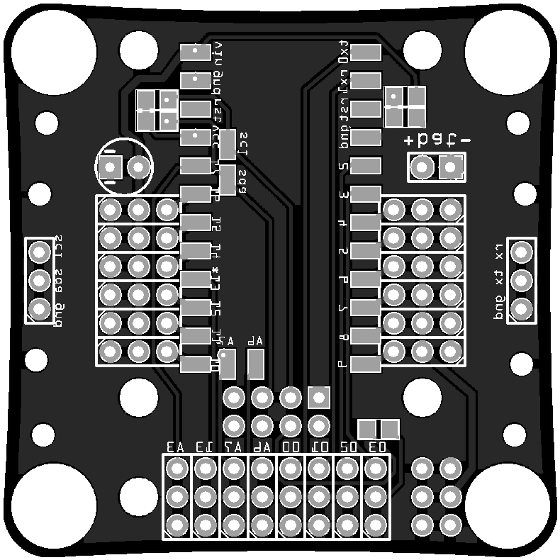
What's on the PCB?
03/02/2016 at 09:14 • 3 commentsTime to talk a little bit about the new printed circuit board and what will be there available on it. Let's take a look at the bottom of it (note that this image is mirrored -- that is, it's as if the board was transparent and you are looking from the top):
![]()
The two rows of pads in the middle are for the Arduino Pro Mini module, with ATmega328p on it, running at 8Mhz. There are also some additional pads for the I²C and analog-only pins.
The two rows of 3-pin headers running along the Pro Mini are servo sockets. Since the servo plugs are relatively bulky, I had to put them close to the center of the board, so that the moving legs don't collide with them. This is pretty much the same as with regular Tote.
The 4×2 header below the Pro Mini is for an ESP-01 module. I decided to give up on controlling this robot with a TV remote, and instead will go for WiFi, mostly because that makes it easier to use it for more advanced stuff. If you want, you can still connect IR sensor to one of the free pins, and add the code for it, but by default the control will be through the esp8266 chip.
Below that the 8×3 header breaks out all the free pins from the Arduino, so that you can connect your own things to them. Each pin also has a 3.3V power and ground pins next to it, because sensors are likely to need that. The pins A6 and A7 are analog-only, and the pins 03 and 02 have interrupts. Also, pin 13 has a build-in LED on the Pro Mini.
The 3-pin headers on both sides of the robots break out the I²C bus and the serial interface for the ESP8266. The I²C bus is used for internal communication and has pullup resistors to 3.3V, but you can also connect your own hardware to that, as long as the addresses don't clash. The serial is mostly for debugging purposes (it can't be used for flashing the esp, because of the pullups on the I²C line). The I²C line and power are also broken out on the 6-pin header in the lower right corner.
In the upper right corner there is a battery plug, and a voltage divider connected to the A7 analog pin. If populated, it can be used to monitor the battery voltage -- but then of course you can't use A7 for your own sensors. The ESP8266 also has the possibility of monitoring its own power voltage, so I will see how well that works, and if it's better, I will leave that unpopulated.
The circle on the left side of the board is a place for a capacitor, to protect against brownouts. Next to it are the two resistors acting as I²C pullups.
And that's it. It's not very complex -- to be honest, the PCB is mostly to just keep all the things together and act as the robot's body.