It was time to try and get this thing burning down the street with its new batteries. We got to burning, at least. We definitely got to burning. Check out the video for the full story. Details below.
Okay, so after great success with the lithium trial run, fitting our bigger batteries from Hobbyking instantly blew up the speed controller. When we dosed it with some hot, fresh amps, the FET was killed instantly. Most disappointing! Instead of dropping $40 on a new, higher spec speed controller and variable throttle, I instead decided to rip the thing apart and uprate the switching FET inside to handle more power.
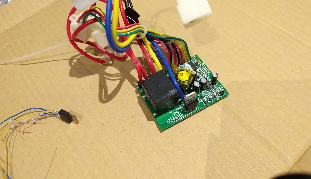
The speed controller, right, with the old blown IRFB3607, left.
However, I had a problem - the IRFB3607 inside was rated to handle 80A & 75V. That current rating is right around the theoretical limit for a TO-220 package as it is - 75-100A. Replacing it with another TO-220 wasn't going to cut it. Instead, I had to get creative - I decided I'd go with parallel FETs to handle the strain.
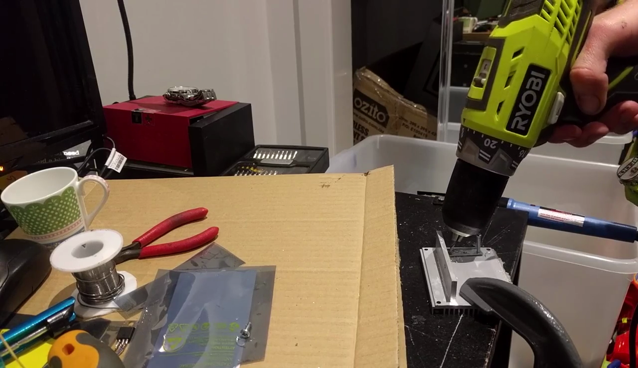
Modifying the heatsink and mounting hardware for parallel FET GOODNESS.
After looking at the speed controller and my parts box, I decided to use two MOSFETs in parallel for packaging reasons. I chose the TK100E08N1, rated at 214A & 80V. This is an example of the manufacturer rating the gate current capability of the silicon, ignoring the fact the device package can't effectively handle in excess of 100A.
I used a small piece of veroboard and modified the existing mounting hardware to fit the parallel FETs to the original heatsink. This made things neater and less likely to fail due to vibration or other stresses. Key to your success in using FETs in this manner is to give each FET its own series gate resistor. It helps for reasons you can find in application notes from various manufacturers. Oscillation is the biggest problem. I used a couple of SMD 10 ohm resistors I scavenged from an old hard drive.
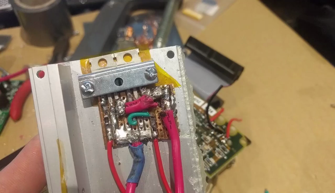
The parallel FET assembly. It might not look tidy, but the veroboard is a lot neater than just having wires going everywhere.
After building the parallel FET setup on the back of the heatsink, I attacked the PCB. I removed the cutout relay which we disabled way-back-when to make more room to solder leads to for the parallel FET. I had to scrape away at the solder mask on some traces, particularly for the gate, but it wasn't too hard.
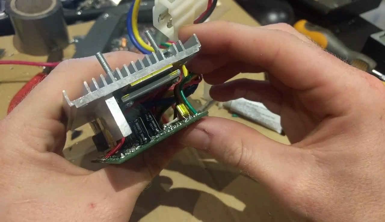 Reassembling the speed controller. The new FETs are a good fit and make excellent contact with the heatsink.
After reassembling everything into the scooter, it was time to test. AND IT WORKED.

IT WERKS!
SORT OF. The scooter was initially incredibly quick, but quickly lost power. I couldn't get close to the previous speeds I'd reached and there was a hot, burning smell. It was the motor.
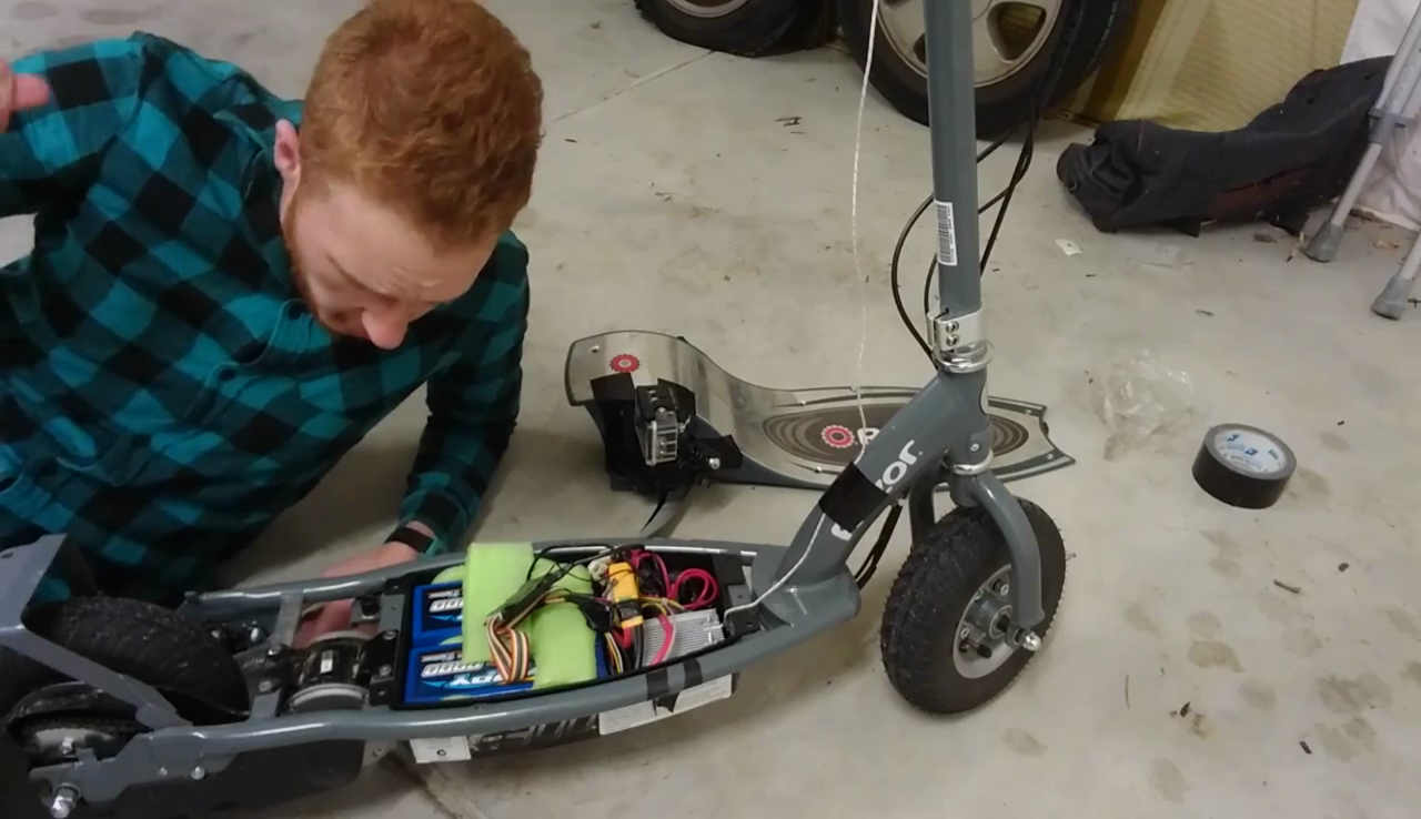
Me, glaring at the motor that just burnt me in dismay.
At this point, I cannot warn you enough. DO NOT. UNDER ANY CIRCUMSTANCES. TAKE A BURNT OUT MOTOR INSIDE YOUR HOUSE TO WORK ON. My lab space and kitchen STILL smell like fiery death a WHOLE WEEK LATER. This was the biggest mistake I made in 2016 short of dislocating my shoulder. I am not even kidding.
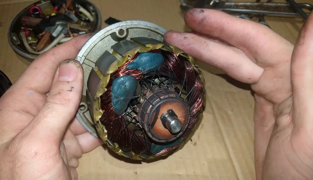 The smell is indescribable, and, as I have now found out, has lingered for almost a week.
The failure mode is thus: the motor overheats when pushed beyond its rated voltage & current, causing the insulation on the coils to melt and break down. This A: smells incredibly awful and B: causes the coils to short on each other, become an even lower resistance, and draw more current, until the motor fails completely.
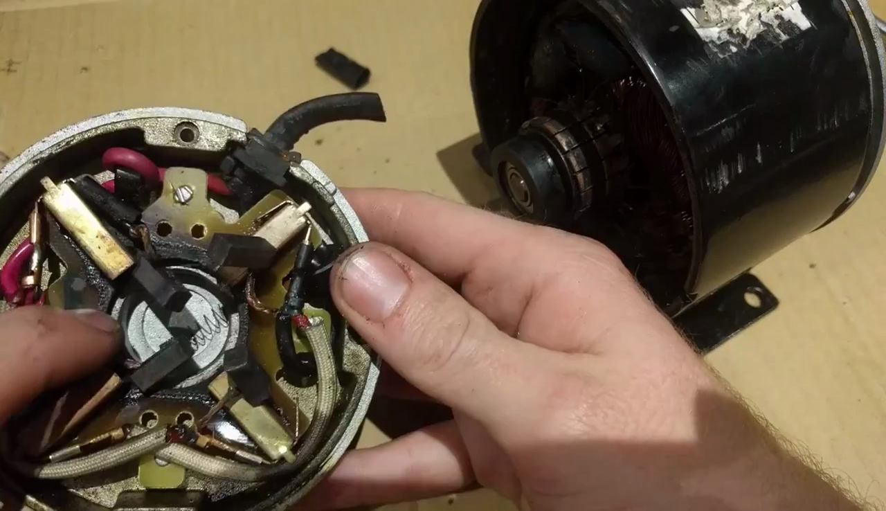
Burnt. Awful. Sad.
Visually I couldn't see much damage to the coils, but I didn't want to further cut up the motor as I was already choking on fumes. After 40 minutes out of the scooter the rotor was still hot to the touch. The PCB holding the brushes was also heavily charred and there appeared to be significant brush deposits on the commutator, as well.
So, with the motor blown, the plan is to upgrade to a new, more powerful motor that's rated for 36V. This leaves me in an uncomfortable position; with even more power than ever, I'd dearly like to switch to a speed controller with a variable throttle to make it more drivable. However, that would undermine all the cool work I did upgrading this one with parallel FETs. Someone decide for me.
Until next time - TK out.
 TK
TK
Discussions
Become a Hackaday.io Member
Create an account to leave a comment. Already have an account? Log In.
I forgot to mention how awesome I thought the 2 "Glow in the dark" FET hack turned out.
Here's something that might help.
http://www.ebay.ca/itm/231354935604
Gas gauge and consumption meter for batteries. B-)
It could also save your motor/battery/esc, without IMPOSING a limit like the limiter did.
L8r
Are you sure? yes | no
All I can say is; My e-200 came stock with variable speed. I like toddling down the sidewalk and through the park with the bi-pedals, then zipping away when the path is clear. All your good work will live on here at HackADay. Just advise fewer batteries to save the motor. Or to start with a bigger motor. I always advise people who are going to soup-up their cars, "Start at the back wheels and tires, work through the drive train and clutch, and then tackle the motor." Too late for you to use that strategy I guess, unless you start from scratch.
Are you sure? yes | no