I took a bit of time away from GimbalBot to spend time up north and to think about the basic craft design. There were a pair of loons at the lake that had a few babies. PSA: baby loons are damn cute. Glad I had a decent pair of binoculars on my Christmas list (thanks, Mom!). Note to self: hanging out with baby loons helps one to see the big picture.
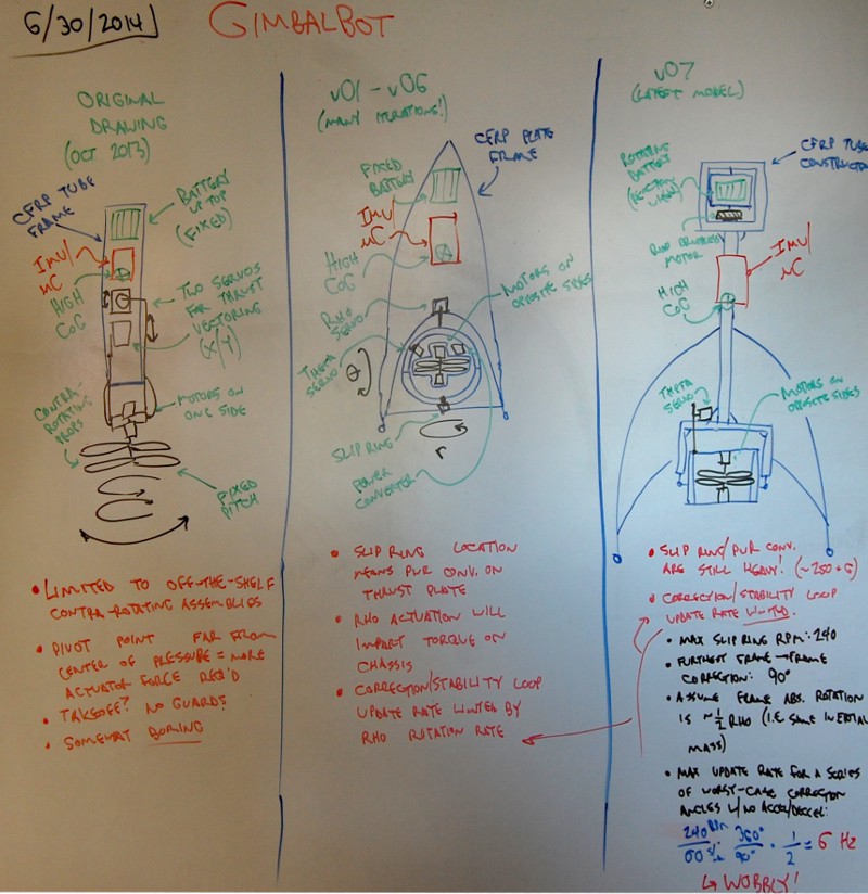
Technically, the following drawing (taking up the left 60% of my office whiteboard) was produced prior to the last project log. My bad, I've been holding out:

A few notes:
- Not relevant to the drawing content, but taking a picture of my whiteboard is a bit of a pain. I usually photograph it in the evening; my office has south and west facing windows, so the glare gets excessive between 6pm and 9pm during the summer. The above drawing has a bit of global brightness/contrast tweaking and local brightening/darkening to improve legibility; additionally, I took the picture at an off-angle so it's de-distorted. Apologies for the lack of clarity!
- Left pane: original drawing (Oct 2013)
- This is a pretty straightforward copy of the original sketch I had in the Project Idea Diary. Some kind of hollow CFRP frame, either a tube or a truss. A commercially available contra-rotating system that spins the props from one end using a hollow shaft. Servos for X/Y tilt control.
- It seems dumb, but the 'somewhat boring' comment still stands. The off-the-shelf contra-rotating propeller assembly requirement really pushed this design to the chopping block; I couldn't find good thrust data online but I think those units are generally sub-kg systems. In any case, I moved on from this concept before actually estimating thrust::weight ratio using a CAD model, and never built in a landing system or really gave the servo linkages much thought. I would have run into issues with the inner ring servo, since rotating the outer ring would affect both angles.
- Center pane: v01-v06 (end of April 2013-Juneish)
- Many revisions here, as noted. All of them used a 'flat-pack' style CFRP frame, ideally waterjet cut from large-dimensioned 1.6mm stock. Switched to a polar thruster design using a slip ring; at some point I did some electrical calcs and realized that I'd need to deal with voltage conversion. Converter located on thrust plate. Thrust:weight ratio in the 1.3-1.5:1 range.
- Got concerned with cost; large CFRP plates aren't cheap, and the waterjet work would have been pretty expensive too. Also, once I thought about the torque effects from the thrust plate I decided to change the design substantially.
- Right pane: v07 (late June)
- The last full CAD model. Reaction wheel using the battery packs, slip ring and rho control (now a brushless hollow-shaft motor) mounted up top to improve weight distribution. Thrust:weight ratio around 1.3:1 or so.
- Had a few issues, highlighted on the board:
- 6Hz max update rate if corrections are 90 degrees off from each other (worst case scenario). Limited by slip ring.
- Brushless motor is heavy and draws a decent amount of power (probably). Also needs a controller.
- Thrust:weight of 1.3:1 assumes pretty optimistic thrust output. Remember, I was driving the ESCs at 16vdc or so... still didn't know if 12vdc would give me enough thrust.
- Real talk: Had some issues with the power converters (see previous post). Got a bit discouraged and had to walk away for a brief period. I'd say I've got a pretty good chance of getting the remaining unit to work (especially if I seek support from GE), but it was time to move on.
- Slip rings and matching hollow shaft motors are surely useful for other stuff. I'll put the power converter in my rarely-used-but-valuable parts bin and get it out when I've got an application in ten years.
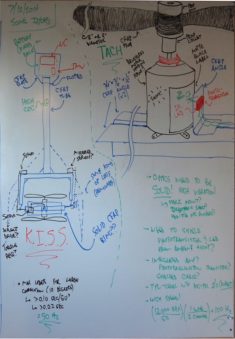
So. Like I said, I had a bit of time to think. I tried to distill those thoughts into another whiteboard drawing:

- Left drawing: GimbalBot v0.8
- Ditched the reaction wheel and used a fixed plate for the battery and uC/IMU mount. Bam, saved 250+ grams.
- No more rho/sigma control; back to X/Y. 6 Hz --> 50 Hz update rate using the servo/correction angle assumptions shown.
- Propellers face away from each other. Brings more weight in while pushing thrust out a bit; not sure how this will affect overall thrust output but I'm willing to bet it's not by much. Dramatically simplifies the thruster design.
- Servo linkage ideas shown but not really developed; I'm going to save that for the CAD model. A few thoughts on this:
- I want to balance the weight and avoid torque across the rotated structure, so two servos is an appealing solution; however, I'm a bit worried about syncing them up, especially when I first turn the system on. Don't want them to fight each other. Might want to build a shaft of some kind. Could use the shaft as an adjustable torsion bar to eliminate backlash... hmmm...
- Direct drive could be cool to eliminate backlash further, but servo mounting might be tough (and wide).
- Can I build the ring from a section of large CFRP pipe? Does that stuff exist? Could I use a foam tube wrapped in CFRP and resin? Do I want to get in to CFRP fabrication? Time to do a bit of research. Not the end of the world if it's square.
- Torque calcs are a good idea for the servos. Maybe I'll just assume I'm lifting the whole structure from a static point? Should I calculate maximum torque as if the pitch ring is rigid with respect to gravity and the servos are lifting the rest of the structure? Realistically, I don't need more than +/- 10 degrees off the gravity vector.
- Need a landing system that can be broken down and stored, maybe inside the frame tube. GimbalBot should be able to travel.
- K.I.S.S.: Keep It Simple, Stupid!
- Right drawing: Tach
- Realized that I'm currently planning to use the vertical accelerometer axis as the input to the thrust control loop (the one that keeps the craft vertically stabilized). If I can accurately measure RPM of each motor and build a table that relates those values to acceleration readings from a test run, I can use RPM differential and individual motor speed as a leading indicator for both the longitudinal axis' rotation and the vertical acceleration. Feed forward control, just like a fancy boiler!
- 100 Hz acquisition is easy with a decent detector. Need to run some tests on the motors with matte paint to be sure my signal is clear. Ideally, the processing circuitry between the phototransistor and the Due's digital inputs is minimal. Might need something similar to a debounce algorithm in software to kill noise, or something in hardware.
- Shielding? Maybe felt, or something else flexible and glued on to the CFRP angle? Ambient light = bad. Also, shielded cable to avoid EMI from the ESCs.
- Might want to mount the tach bracket to the frame using vibration isolating bumpers. I've got a pile of HDD shock bumpers somewhere in the basement from a recent PC build, those might work. The area around the motor gets pretty crazy at full power.
Dinner time, then I might hit CAD a bit tonight to start v0.8. Hoping to finish the model tomorrow afternoon and get parts on order so I can start building. I would love suggestions and comments over the next 12 hours or so; as the title of this post indicates, I'd like to finalize the design and get crackin' on a prototype!
- Zach
 zakqwy
Discussions
Become a Hackaday.io Member
Create an account to leave a comment. Already have an account? Log In.