-
Hackaservo.io
08/14/2014 at 03:28 • 2 commentsSo I've come to the conclusion that my servos were designed to actuate smaller masses, and as such their control parameters aren't exactly suited for the larger than normal loads I'm putting on them. The vibration I'm seeing at the end of each stroke--particularly for the outer servo--looks suspiciously like ringing due to an under damped loop:
![]()
source: http://woodharbinger.com/site/index.php/control-loop-tuning-for-building-performance/
It's hard to say without looking at a response waveform, but it seems like adding a bit of derivative could help tamp down the ringing a bit. Or dropping the proportional gain. Or playing around with it for half an hour, because putzing around with PID loops is actually really fun.
I got in touch with the support folks at the company that manufactures the servos I'm using; they're high end units ($150 each for hobby stuff? yup!) but they aren't explicitly programmable. It's a bit odd, and something I didn't think to ensure when I ordered them; they have lower end servos ($50ish) with lower speed/torque specs and plastic gears that can be programmed, and the top-of-the-line units (one step above mine) are also programmable. But not the series I selected.
In any case, the customer support guy gave me an unfortunate if not unexpected response--the servo I'm using isn't programmable, and it works well for the applications it's designed for. He recommended taking a look at the higher end unit as it's the highest performance device they've ever built. I told him that I wasn't interested in investing in additional servos unless the programming features would allow one direct access to the servo loop tuning parameters; needless to say, he hasn't gotten back to me yet. Oh well.
The servos are still excellent units; they're crazy fast and seem to have plenty of torque for the application. I'm afraid the ringing will give me all sorts of problems developing GimbalBot's control algorithms, so I'd like to get ahead of this now. Time to void some warranties!
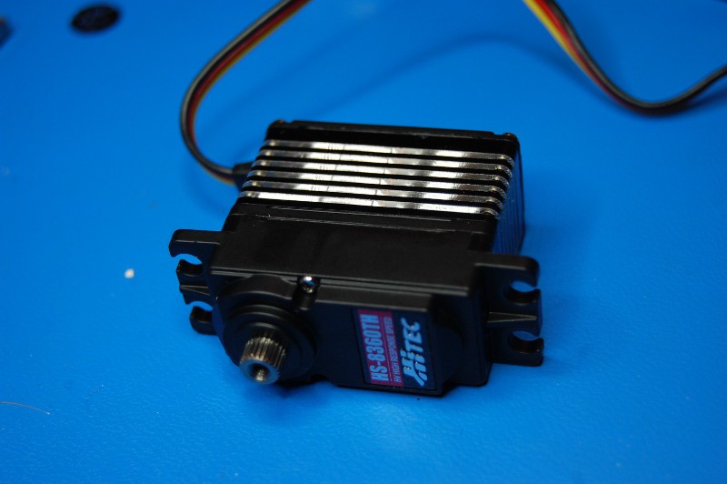
The patient:
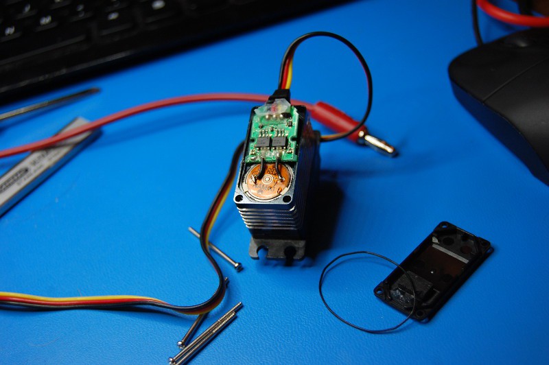
I removed four Phillips head screws and carefully pried off the rear cover; it was glued on to the circuit board pretty well, so this was a bit of a delicate operation. Lots more glue on the board:
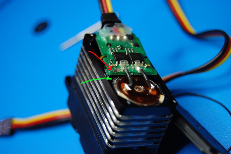
Here's where it starts to get annoying. Yeah, more annoying than a glued down circuit board. You can see the two motor leads in the picture above; it appears that the motor also grounded to the circuit board through a third wire, barely visible in the following picture (the green arrow shows where the wire connects to the motor, while the red arrow shows where the wire is soldered to the circuit board under a heap of glue):
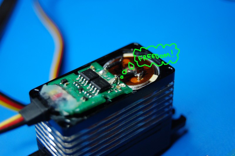
Curiosity quickly got the better of me, so I scraped off the glue and headed up my soldering iron. A bit of braid made quick work of the offending solder joint:
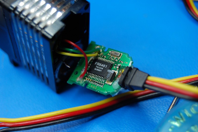
... allowing me to lift up the board:
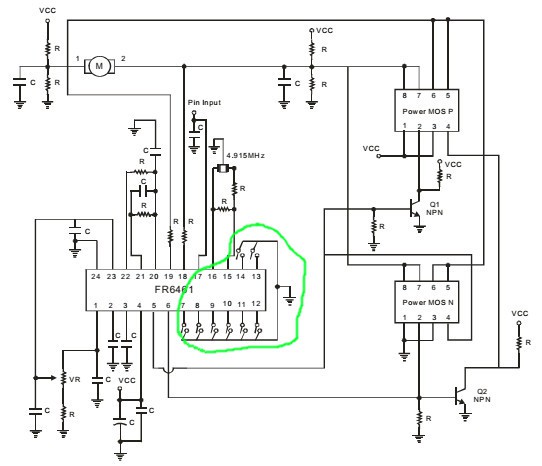
Now we're cookin' with gas. A quick Google search turns up FR6461 as a digital servo controller chip. I found a datasheet (*.pdf warning) that gave me all sorts of (potentially) good news. Take a look at this part of the datasheet:
The eight configuration pins are 7, 8, 9, 10, 11, 12, 13, and 14; in the picture above, you can see the first six are tied directly through six black components to a copper plane, which has vias that carry it to the servo ground lead. The other two pins are similarly connected on the other side. That means, assuming the components are just jumpers, all eight bits are currently low, meaning the Deadband is 0.7 uS, the 'Stretch' is X1, the Boost' is 156 uS, and the Max Duty is 97%.
So what do those mean? Deadband is pretty obvious, and is presumably measured in raw servo pulse width. I'm assuming Max Duty is the maximum motor duty cycle; given the heatsink and general "extreme performance" of this servo, I'm not surprised it's set to 97%. But what are Stretch and Boost? Anyone have any ideas? I can always run a few tests, but it's a bit of a pain to pull various jumpers, resolder the stupid motor ground wire, and reinstall the servo in GimbalBot more than once. At least it looks like the eight bits don't have to be pulled high; the reference schematic from the datasheet shows eight momentary switches:
Should I try to install external tuning switches on the servo, at least for Stretch and Boost? Is my soldering up to snuff?
-
Motor Cooling
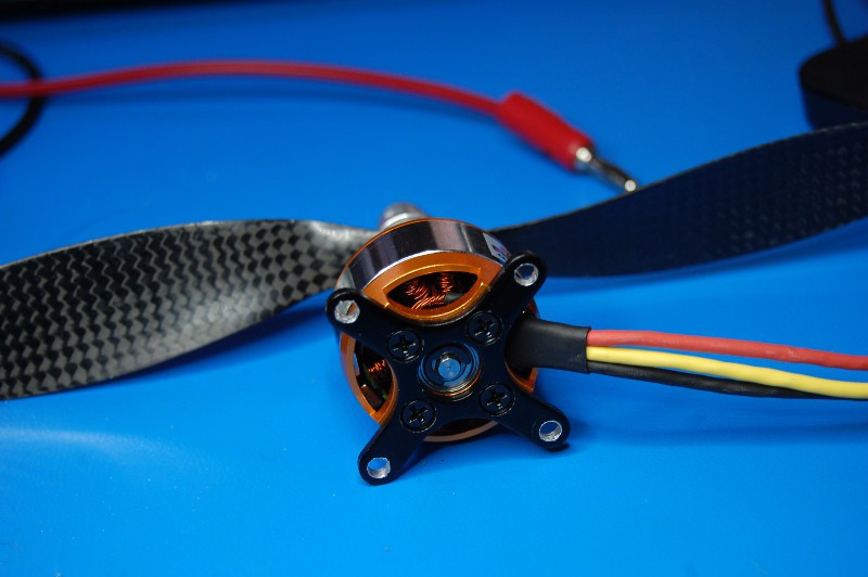
08/13/2014 at 03:15 • 6 commentsI had a lengthy conversation with Jefito yesterday evening and ended up spending some time doing a bit of CAD work. He brought up motor cooling; specifically, the fact that I might be able to get better performance out of my brushless motors if I could figure out a way to cool the stators during operation. He had a few ideas beyond simply increasing airflow, including some novel thoughts featuring dry ice or liquid N2. Definitely worth considering, as GimbalBot's flight time probably means the few minutes of coolant I could carry would be adequate. It's been many years since I've used LN2 in a personal project and I've been looking for an excuse to find a good MN supplier.
However, we ended up discussing air cooling as a simpler alternative. I came up with an idea for directing additional airflow into the back of the motors, taking advantage of the fact that they already have large cooling passageways machined into their backs (with vents opposite those holes on top of the motor rotors):
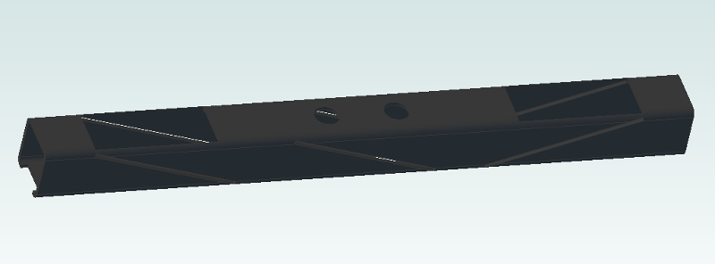
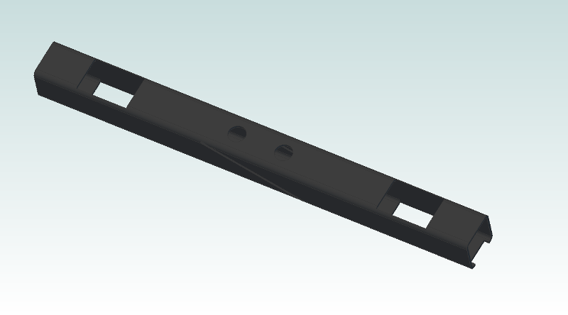
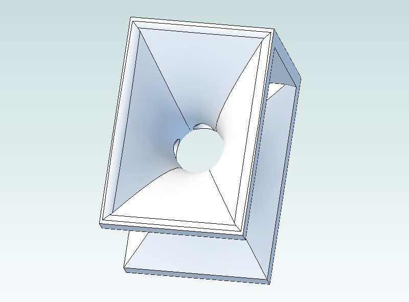
Using the hollow CFRP motor mount as a duct, I used a series of diagonal slots to orient three CFRP plates to deflect airflow. I also cut a few holes where the motor sits (and in the CFRP motor mount plate, not shown) to direct airflow into the two motor cavities:
![]()
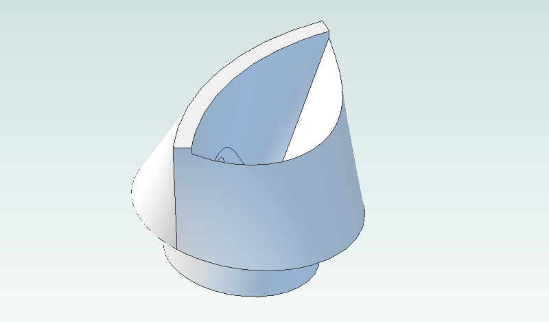
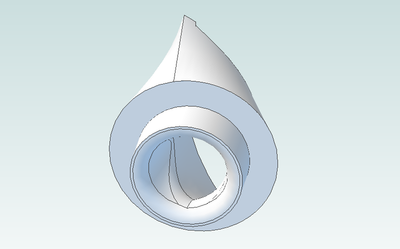
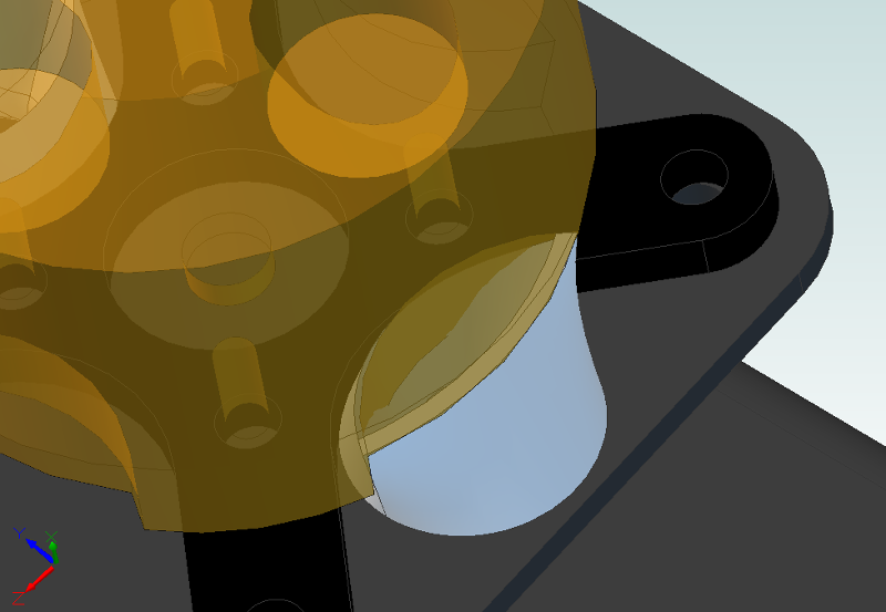
Here's a confession--I've never done a 3D printing project. I've certainly played around with 3D printed stuff, and hit the button to run a stock program or two; in college we had a Z corp SLS setup that we used for resin bonded sand, but it was being used for things quite a bit so I set my sights elsewhere. Since then, I've always gotten hung up on details like machine/material cost and the structural deficiencies of commonly available rapid prototyping compounds. In this case, however, 3D printing is the perfect fit for a few nozzles:
![]()
Yaay fillets!
![]()
I dropped the opacity of the motor down a bit so the fit between the nozzle and the motor/mount makes a bit more sense:
![]()
I need to tweak the dimensions a bit, mostly because my original measurements of the motor vents weren't intended to be highly accurate. But you get the idea:
![]()
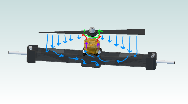
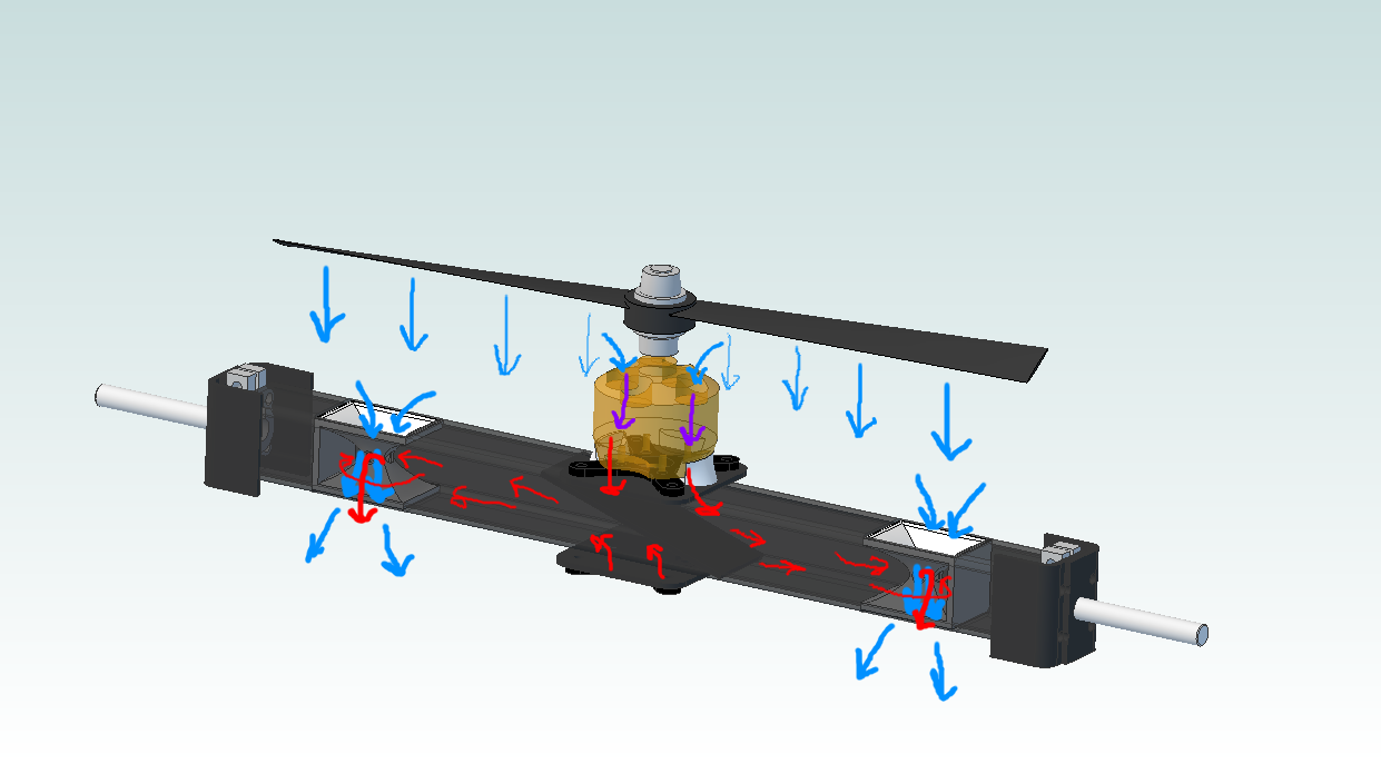
Sorry about the crudely annotated drawing. Green is motor rotation, blue is cold air (with length somewhat proportional to velocity), and purple and red are air getting progressively hotter as it travels through the motor. The idea is that the air velocity below the propeller is not uniform; instead, the velocity increases as you get to the perimeter of the blade:
![]()
source: http://www.gorhamschaffler.com/system_effects.htm
Or at least, that's what my understanding of propellers suggests. This design is intended to capture some of that high velocity air and send it back through the motor. Think the pressure above the motor will be low enough to cause a decent amount of air to move? Or am I naive to assume that the velocity profile of the air coming off the fan blades can be described so simply, without accounting for the myriad of factors (distance from propeller, airflow disturbances caused by the frame, propeller shape, lack of duct compared to the picture above, etc) involved in a good simulation? If I follow this plan, I'd cut a fairly large hole in the CFRP motor mount and run instrumented cooling tests at a constant thrust (or current) with various inlet opening sizes and locations.
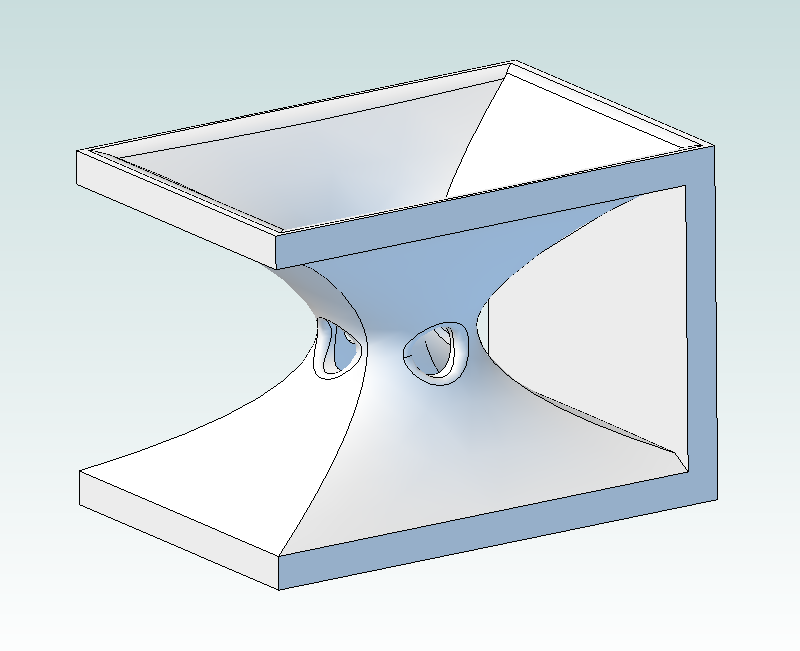
So here's another thought: What if I design a venturi that will pull air through the motor and exhaust it through the CFRP motor mount? I'd still use the same nozzle, but the motor frame might look more like this:
![]()
Then it's time for a bit more 3D printing:
![]()
![]()
These little guys fit into the motor mount like this, with air velocity now represented by line thickness instead of length:
![]()
If you aren't familiar with the venturi effect, take a read through the Wikipedia article. Essentially, Bernoulli's principle says that conservation of mechanical energy along a streamline (along with a few assumptions about the fluid, such as incompressibility or at least fairly low speed) means potential and kinetic energy can change, but must sum to be the same figure. If you do the math, you'll find that the velocity of a fluid traveling through an orifice is proportional to the square root of the pressure drop across that orifice, corrected for fluid density:
![]()
source: http://en.wikipedia.org/wiki/Venturi_effect
where p1 and p2 are the high and low pressure ports, rho is the fluid density (assumed constant throughout the system--i.e. incompressible) and v1 and v2 are the velocity at the narrow and wide point in the system. So... I've got a high velocity jet of fluid (air) being forced through the venturi by the propellers, and the four low pressure ports are near the vena contracta. The pressure differential between this point and the top of the motor stator should give me some flow through the cooling system. Again, I'm hoping that the holes above the motor will provide an adequate high pressure side to generate flow through the venturi.
So--I'd love to hear some thoughts on this before finalizing dimensions and sending the 3D printing order out. I'm actually fairly comfortable sizing a venturi, since I spent a few years selling industrial differential pressure based flow meters (amongst many other types). I'll need to make a few assumptions about things like velocity, but I should be able to get a rough idea of beta ratio (the ratio of the constriction diameter to the entrance diameter) and port cross sectional area. I think it's a better solution than the flow diverter model since it should have a much less severe effect on the propellers, and I'm much more confident that I'll be able to achieve an adequate pressure differential across the stator to generate some airflow. Having said that, the turbulence and general sketchiness of the airflow that close to the propeller could cause all sorts of unpredictable effects that make the system fail miserably.
More to come on this tangent, I assure you! Comments?
-
First vectored thrust tests
08/12/2014 at 12:02 • 0 commentsLong video--my terrible Internet connection meant it took 3+ hours to upload, so I couldn't post it last night. If you're impatient, feel free to skip to 3:25 or so:
-
Good news, bad news.
08/09/2014 at 01:59 • 1 commentI ran GimbalBot's first thrust tests a few minutes ago. EXCITING!!
In the video, you can here me (and my wife) getting concerned about the smell coming out of the motors, so I shut the test down at 1300g or so. Later on (also after realizing I had a prop on backwards, ha!), I got GimbalBot up to 2300g. I ended up running at ~2kg for 3.5 minutes; at that point, the LiPo alarm sounded on one of the cells so I shut it down. Including the other tests, I'm guessing I could have held out for 4+ minutes at that thrust with a topped off battery.
So... bad news first, I guess. I had the throttle pegged to hit 2300g, and I wasn't able to sustain that number; presumably the battery voltage started to sag pretty quickly. After running the tests, the motors were quite hot to the touch. As in, I couldn't touch them--really really hot. REALLY hot. So what happened?
Hard to say. My 10" props arrived so I naturally strapped them on immediately; maybe the large props overloaded the motors and the RPM started to sag. I re-read the motor datasheet (well, brief website description) and it looks like the 80% assumption was a bit optimistic; they guarantee 75+% for a certain amperage range, but I was definitely exceeding that given the short battery life. Either way, not a particularly good showing from the motors.
Now the good news: the servos were rock solid. Granted, I didn't try to change pitch during the test, but I was still happy to see them hold the motors perfectly straight. Everything else seemed to hold up well too; the servos didn't heat up, and the ESCs got a bit warm but certainly not enough to be concerning. The battery was fine.
Next steps? I'll probably charge the battery and try again with the 9" props. After that, I might start looking for bigger motors. Any suggestions?
-
2DOF servo tests
08/06/2014 at 02:37 • 2 commentsI got the outer servo mounted and its linkage sorted; I also soldered up a temporary wiring harness so I could easily power both axes. First, a quick video:
As I mentioned in the video, I got lazy--no ramping on the servos. I also didn't see Curtis' excellent comment until after these tests; I'll be adding a cap to the servo supply leads to avoid sag on the power rail. Great call. Now, a few pictures:
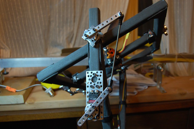
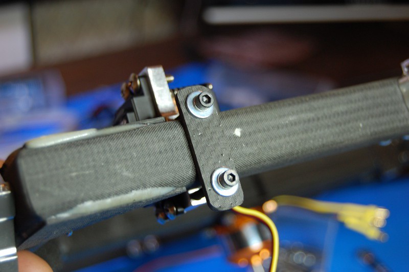
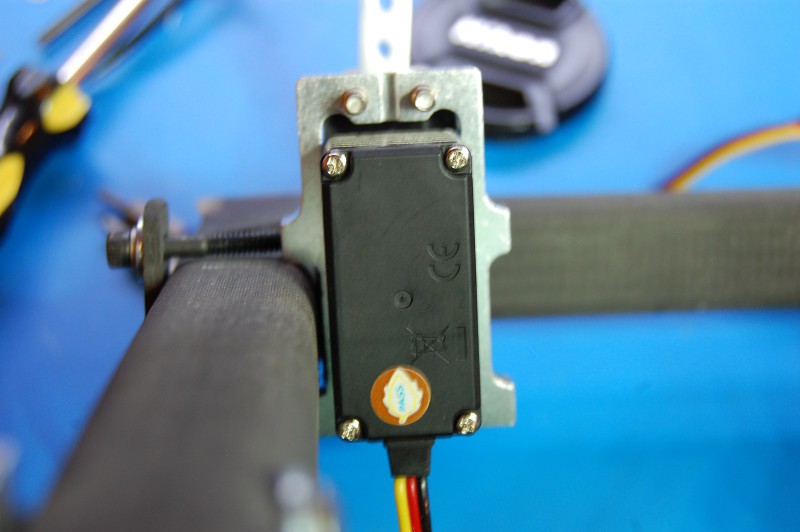
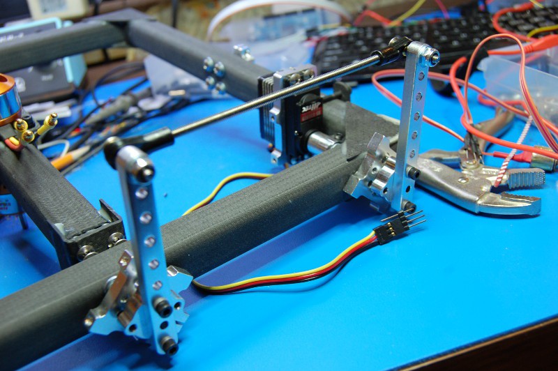
Outer servo mount and linkage, shown with GimbalBot upside-down. Note that the servo gets a bit of a mechanical advantage since its linkage arm is short; I actually tested the servo with equal length arms to no ill effect, but I decided to pull it in a bit for further tests:
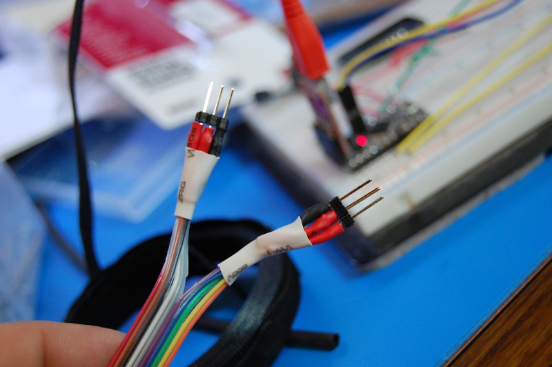
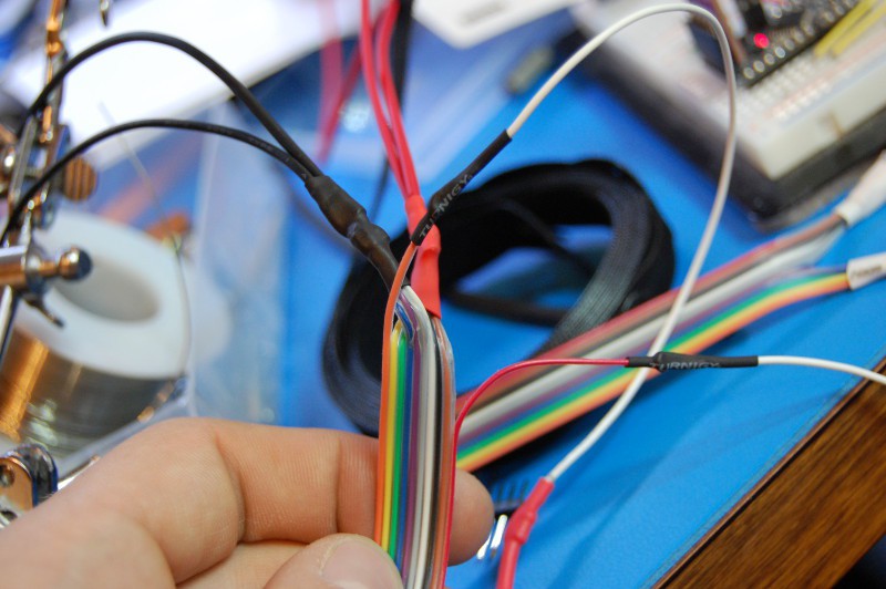
I used a few bits of header to build a temporary wiring harness so I could test both servos simultaneously without yanking the wires out of my breadboard. The ribbon cable I had on hand is a bit thin, so I doubled up the power and ground leads:
Did I ever mention how much I love heat shrink tubing? On a more serious note, I'm glad I did a continuity check on the harness; I'd accidentally swapped a few connections between here and the servo connections, so I did the following portion twice (the second time after a dinner break):
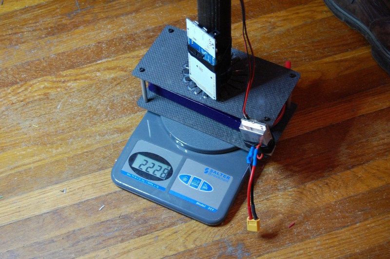
No surprise here: GimbalBot needs to go on a diet. I figured I would be a few hundred grams overweight, especially including the spool of heavy-gauge wire I'm planning to use to power the brushless motors (the wire alone weighs 150g). I also didn't account for nuts and bolts in my drawing. Or space glue. Oops:
I'm not bummed about the weight. I've got a few pairs of 10" props on the way; the prop thrust calculator I've previously learned to trust suggests I'll need to spin them at 9500 RPM to hit the thrust shown on the scale above, and doing so will draw less than 500 watts for both motors including efficiency losses. With my current ESCs and motors, I should be able to top out at 3.5kg of thrust for short periods of time.
3.5kg of thrust. That is a lot.
GimbalBot is kind of scary.
- Zach
-
GimbalBot twitches to life!
08/05/2014 at 04:14 • 2 commentsOkay, so we're not quite hovering yet... but I got one of the servo mounts and linkages wrapped up tonight, and I'm satisfied with its functionality. First, the test video:
A few detail pictures:
Cut, drilled, and shaped a 2.4mm thick piece of CFRP as a backing plate for the servo mount:
Drilling the servo bearing mounting holes without a drill press from one side (since everything is glued up already) lead to some hilariously bad servo alignment. In the blurry shot below, you can see how much material I had to file off the left side of the servo mount to get the shaft to turn freely:
A few linkage detail shots. Only thing to note here is the inordinate amount of time I spent hacksawing bolts down to size. Note to self: buy the right length bolts next time. At least they weren't too short:
As I mentioned in the video, the outer servo will have a much harder job; it has to move the whole mess you see above, and I'm guessing I'd overload the servo geartrain without some ramping. Either way, this feels like a good start.
- Zach
-
v09 build, part 5
08/02/2014 at 14:00 • 0 commentsI got another chunk of fabrication and gluing done last night. It's a somewhat lengthy process since the epoxy takes a long time to set up, but this forces me to slow down and focus on each part.
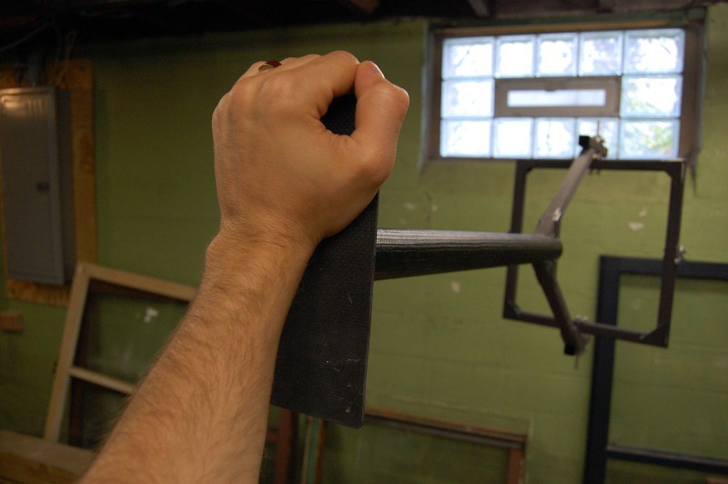
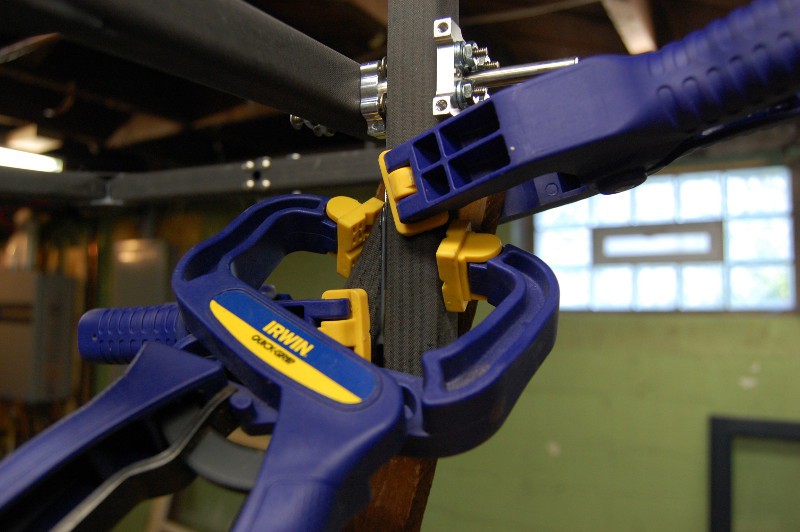
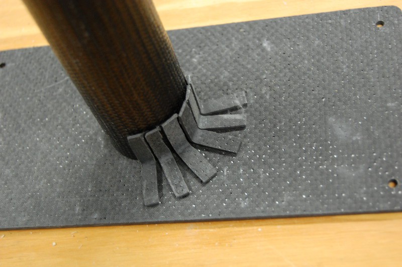
I finished cutting the angled reinforcement brackets for the battery plate and epoxied them to the frame. The glue job isn't the prettiest around, and I wasn't able to clamp them well so the gaps are a bit larger than I'd like:
However, after curing overnight, a quick strength test this morning suggested that all is well. I'll repeat this test once the motors and servos are mounted:
After drilling a few holes for the servo mount, I used the pitch ring to align the second frame upright prior to gluing and clamping. This morning, the pitch ring rotated with minimal resistance--a great sign!
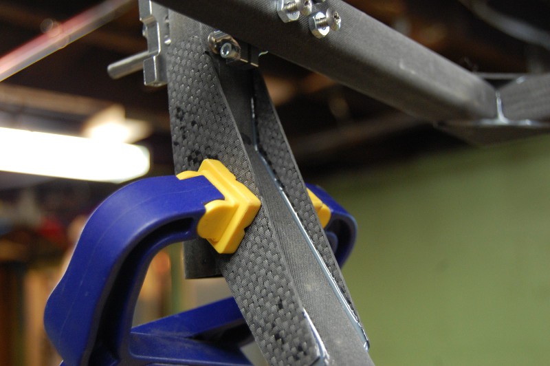
I also cut and glued gussets on the other side, as the joints don't have a great deal of epoxy coverage by themselves. After taking these pictures this morning, I did the same on the opposite side:
![]()
Physical construction, at least the cutting and gluing part, is pretty much wrapped up at this point. So what's next?
- Mount all the electrical gear--servos, motors, props, ESCs, Arduino, battery--and get a final weight number. With the wire and Space Glue, I'm setting the over/under at 2kg even.
- Test servo actuation. This is a big concern; I'm sure I'll need to ramp the servos to prevent over-stressing their gearboxes. I know I've talked about it before, but I might *finally* sit down and do some torque calculations to figure out a good starting acceleration rate. It's been said before, but I really should have done that two months ago. Oh well.
- Thrust testing!!! I'll start with 9" props, but a few sets of 10x4.5s are on the way too. This will be fairly in depth; I'll need to modify the thrust testing rig to grab GimbalBot's frame at the right point. I'm also planning to run battery life tests on the thrust rig to get an idea for flight time.
Exciting times in the world of strange unmanned aircraft. Stay tuned!
- Zach
-
HaD Prize Phase 1 video
08/01/2014 at 16:30 • 0 commentsI posted this to the Project Details section a few days ago, but I figured I'd toss it up as a log update too. I just ran the video through YouTube's stability algorithm so it should be a bit less shaky now (or it will be, once the edits finish processing). Two minutes isn't much time, so hopefully this doesn't just add to confusion about the project.
-
v09 build, part 4
08/01/2014 at 00:04 • 0 commentsNot a huge update here; the extra square CFRP tube stock arrived this afternoon, so I cut the last piece of the frame. I also got my hands on a set of cheap diamond-tipped 1/8" high speed tools which made short work of the holes. Time for more Space Glue!
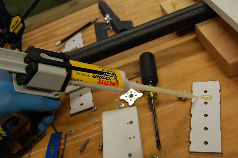
Space Glue, as I mentioned in the last post, has a long mixing nozzle. The instructions suggest blobbing out a bit to make sure it's mixed well:
I reused the jig from last time but added a few modifications to bring the level of the tube up to the right height for the battery tray. The angle bracket reinforcements, to be added at a later gluing step, will provide most of that joint's strength; right now I'm just tacking it in place so it stays put:
While I have prepared both lower square tube sections, I only glued one on at this point; I want to make sure I get the alignment of the second one right, so I'm going to hold off until everything else is set up:
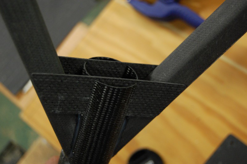
This joint was a bit tougher to glue than expected. Not because of alignment, but because the glue kept spilling out; it seems that sliding joints aren't the best for epoxy. I pulled the gusset back a few millimeters to force more glue in the joint, so it should be fine strength-wise:
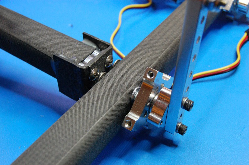
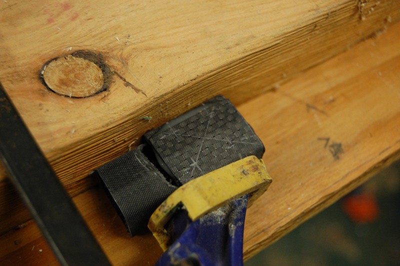
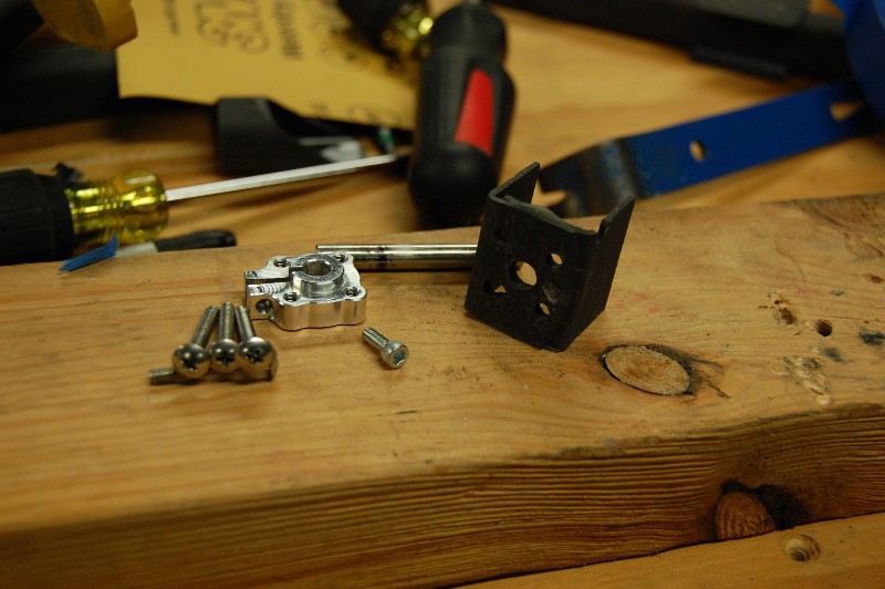
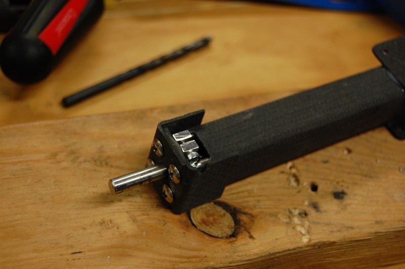
After a few finishing touches with the grinding tools, I also glued the shaft coupling holders onto the motor mount. It's a bit funny--I went to a lot of trouble to make the couplings removable for some reason (presumably so I could shim them into alignment if necessary), and the sliding glue joint forced enough epoxy onto the aluminum parts that they're probably not moving any time soon. Oh well; with the screws all tightened down, I was able to spin the motor mount freely in the pitch ring with minimal resistance. That felt good:
A few electrical goodies arrived today--a large LiPo battery (3S/5000mA), a low battery buzzer (it was $2 or so, seems like good insurance), and an assortment of silicone insulated wire. That means once the frame is glued up, I can put everything together and run some static thrust tests!
-
v09 build, part 3
07/29/2014 at 03:21 • 0 commentsI snagged a few hours after dinner tonight to work on GimbalBot a bit more. Another 2 foot length of CFRP square tube is on the way, along with various bolts and shaft collars. Addtionally, the order with the battery, silicone wire, low battery alarm, and other miscellaneous goodies should be here soon. Some pictures of tonight's work:
Work continued on the motor mount; the two chunks of CFRP angle stock I bonded together this weekend are ready for a bit more attention. Here, I've marked drilling locations for the four mounting holes and single shaft hole for one of these brackets:
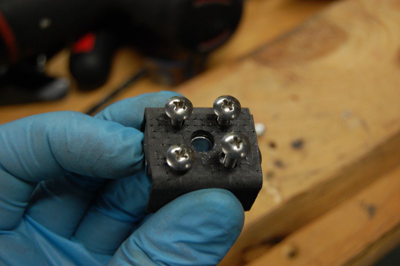
I drilled the shaft hole small on purpose and enlarged it using a rotary tool; I'm not a fan of this design in general because the CFRP webbing between the holes is fairly thin, but it's a tradeoff that lets me easily shim the shaft collar into alignment if necessary. Best I can do is make the holes as accurate as possible:
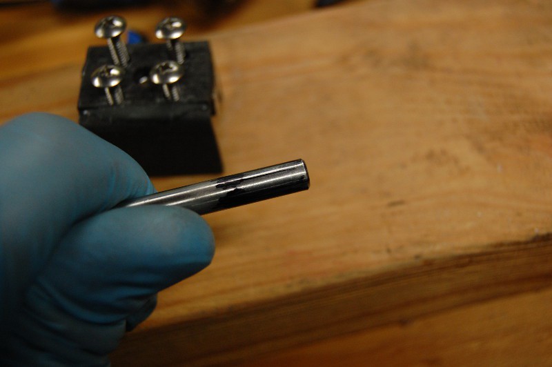
I really should pick up a bottle of Dykem; in the meantime, I used a marker to color the shaft, then checked for rubbed marks to figure out high spots in the hole:
The mounting holes are a bit wide, but they're mostly wide on the edges furthest away from the other holes:
Everything fit together well after quite a bit of filing and checking. I got most of the way through the other bracket but had to stop because I'd worn my HSS grinding tools down to useless stubs; time to pick up some diamond bits. Either way, I decided to hold off on gluing this to the motor mount until I can line it up with the rest of the frame:
Forgot to mention this previously--I made an on-the-fly design change (always dangerous) and increased the battery plate size to 100x200mm. That will give me more room to mount various electrical goodies, and should only increases the weight by a dozen grams or so (and it's top weight). This also lets me run reinforcing brackets all the way around the center tube which should make that joint quite strong. But man--cutting those angle brackets sure is tedious. They kept getting sucked into the vacuum cleaner:
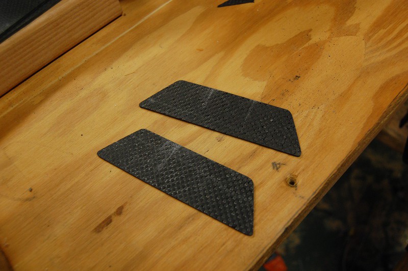
I also cut out the two trapezoidal center tube gussets:
I had to resist the urge to glue them into place since I didn't have anything else to epoxy. Space Glue has a relatively high fixed cost per application due to the 6" mixing nozzle, so I try to use it in batches when possible. Either way, it was satisfying to fit this joint together:
More to come!
- Zach
GimbalBot
Gimbaled thrusters, aerospace-grade adhesives, carbon-fiber-reinforced polymers, and inertial measurement units. This is a space project!
 zakqwy
 Here's where it starts to get annoying. Yeah, more annoying than a glued down circuit board. You can see the two motor leads in the picture above; it appears that the motor also grounded to the circuit board through a third wire, barely visible in the following picture (the green arrow shows where the wire connects to the motor, while the red arrow shows where the wire is soldered to the circuit board under a heap of glue):