-
v09 build, part 2
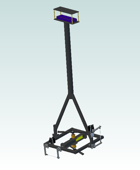
07/28/2014 at 03:10 • 0 commentsToday I focused on GimbalBot's main frame. Or I should say, a part of the frame--specifically, the joint between the 40mm CFRP tube and the two diagonal 23mm square CFRP sections. I figure this is the hardest one to do, and it needs to be as close as possible to perfect; I need the upright square tubes to be fairly well aligned so the bearings turn freely. Furthermore, this is the only glue joint that doesn't mate two large flat surfaces together; while I'm hoping I have enough surface area epoxied between the rounded square tubes and the trapezoidal gussets, actual gluing performance depends a great deal on fitment precision. It's also not lost on me that the raw material value of the CFRP chunks alone is around $150ish, plus a decent lead time. So yeah, I measured about fifty times before cutting.
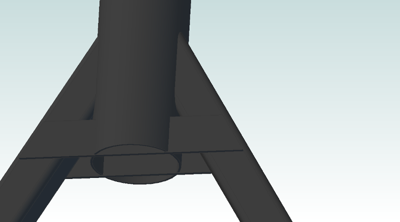
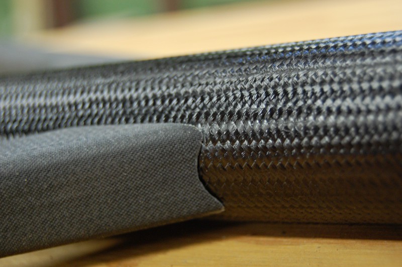
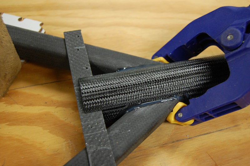
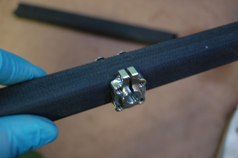
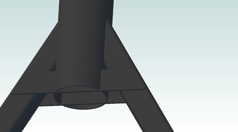
First, a close-up of the joint itself:
![]()
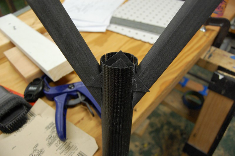
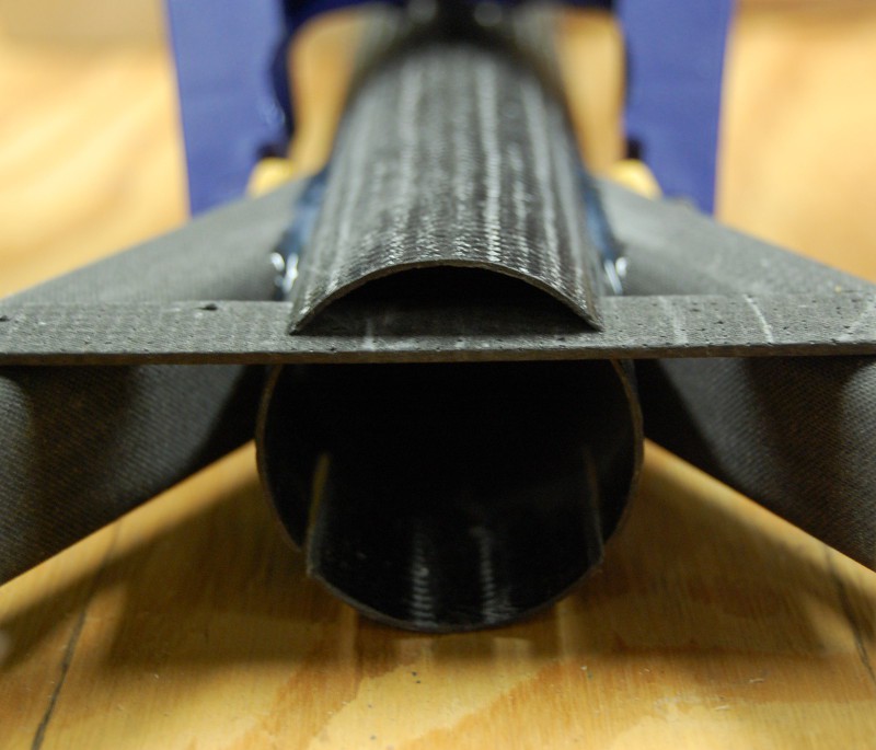
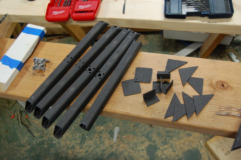
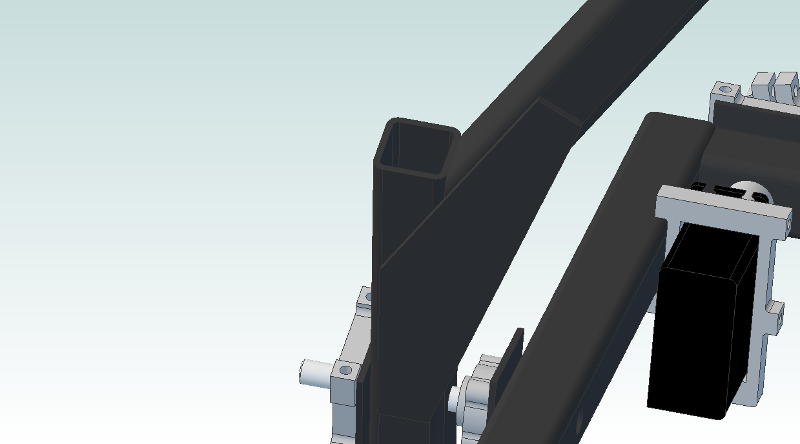
It may not be obvious here, but the two square tubes have their ends rounded at an angle to match the OD of the 40mm frame tube. The gussets fit in slots; ideally, these slots should be angled to maximize available surface area for best epoxy performance.
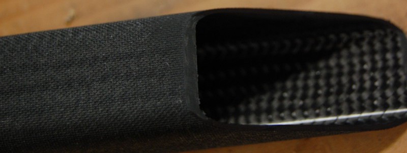
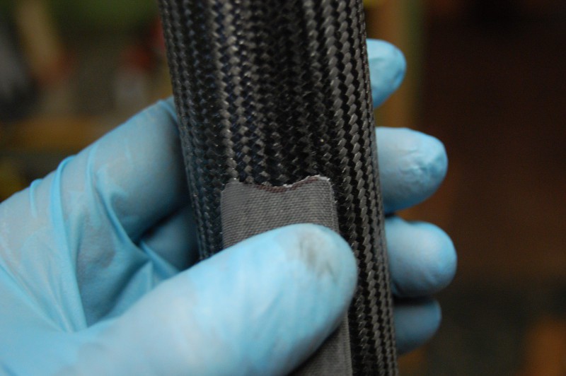
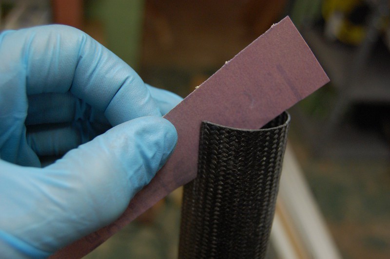
I cut the square tubes at a 30 degree angle and a few millimeters long compared to the print; after sanding each end to the proper angle and length, I marked the sides black to avoid reducing the overall length in the next step:
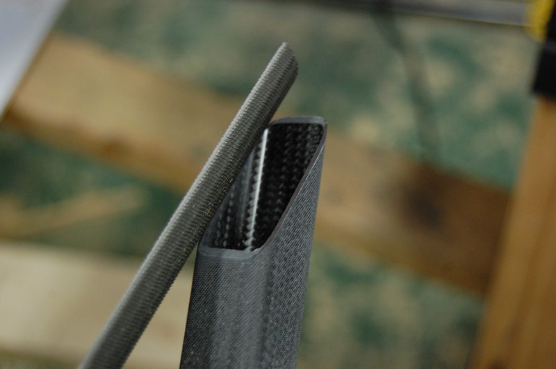
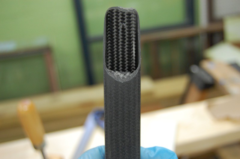
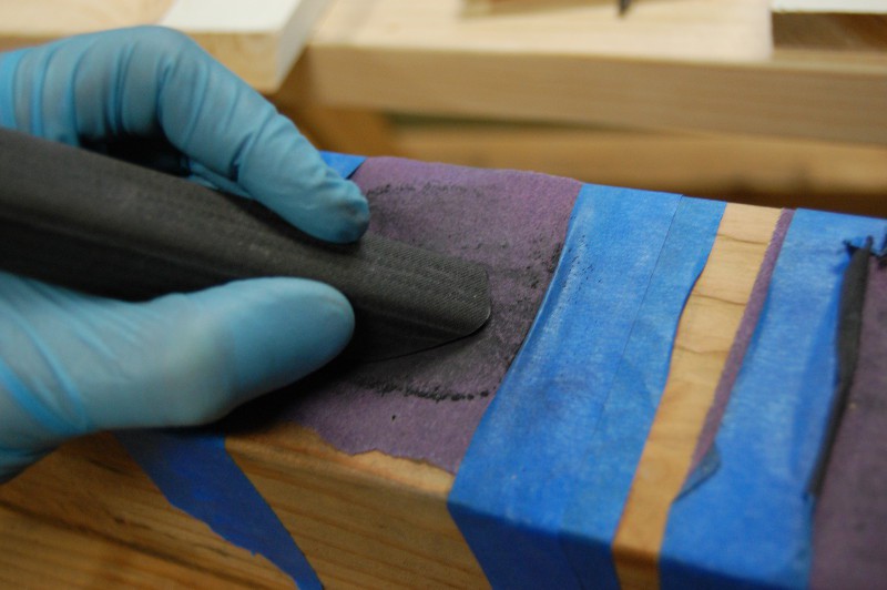
Using a half-round bastard file, I started to shape the top cut of each piece to fit the round tube:
I checked the fit many times against the round tube, sometimes marking off the material that needed removal:
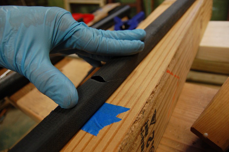
After a few minutes with the file, thin fiberous flash started to build up on the lower curve. I knocked this off with the edge of the file so it wouldn't cause me to overdo the cut (the top hasn't been touched much here, so it's quite uneven):
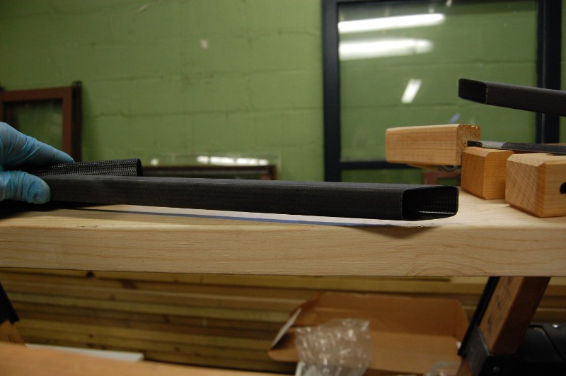
Periodically, I'd check various ends against each other by holding them flat against a board and examining the gap. After a bit of tweaking, I was able to interchange all four ends freely without gaps, suggesting that the angles (while maybe not quite 30 degrees) were identical:
I also held the rounded square tube against the center tube while the round bit was flat on a board; this allowed me to roughly check the squareness of the filing job:
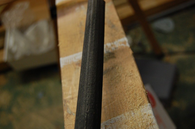
My brand new half-round bastard file was not stoked about its first job, but it performed its function admirably. It's not terribly obvious here, but the shiny marks on the file teeth are bent or rounded off edges. I'd love to find a WC version of this tool, or a half-round diamond impregnated tool of some kind:
The perfect is the enemy of the good. I kept trying to improve the fit until I ran out of excess material:
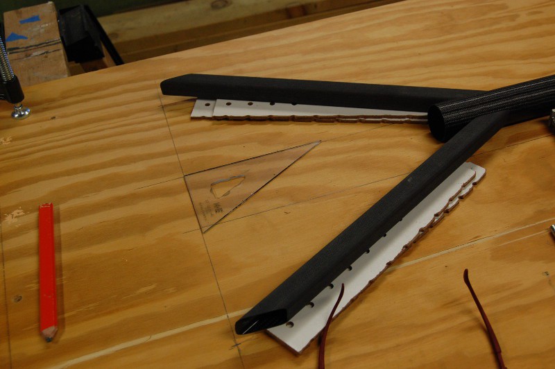
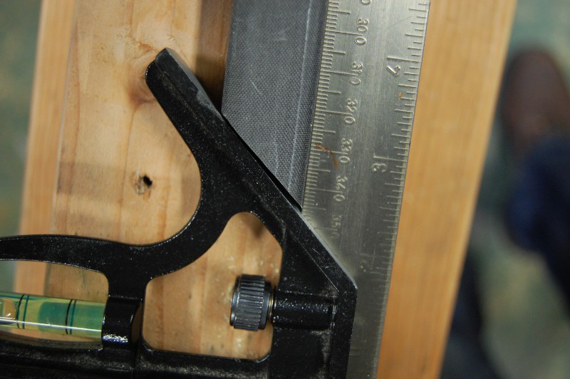
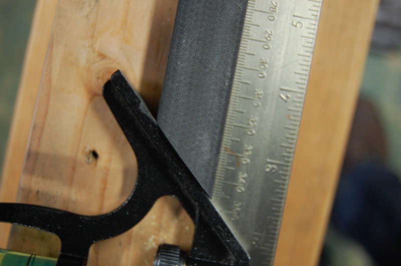
I needed to hold the square tube stock 8.5mm above the edge of the 40mm center tube to match the assembly drawing. I figured out that a bit of scrap pegboard I had lying around was 4mm thick; two pieces stacked up is close enough for GimbalBot. I also built a clamp (shown later) to hold the center tube in place. After marking the center tube to align the two square tubes, I held them in place and dropped marks using a square onto the plywood base. Connecting these marks and checking the angle between that line and a line parallel with the 40mm center tube gave me an idea of the square tube misalignment; no protractor here (just a handy 30-60-90 guide), but I estimated it at ~1 degree or so:
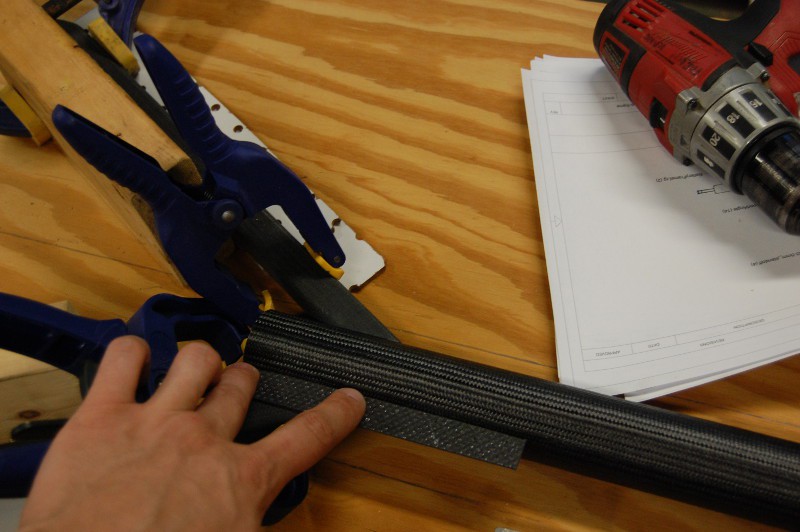
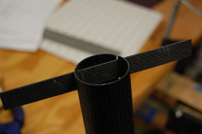
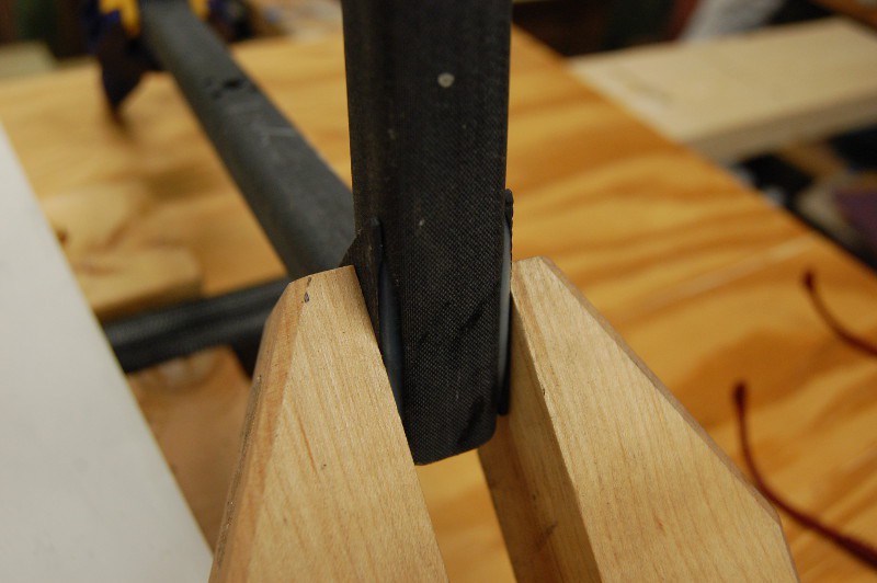
Time to mark the center tube for slots. First, I built a jig to keep the square tubes in alignment and allow me to clamp them securely in place. Once these were sturdily aligned, I used a scrap piece of 1.6mm CFRP and a WC scribe to mark the slots:
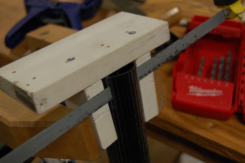
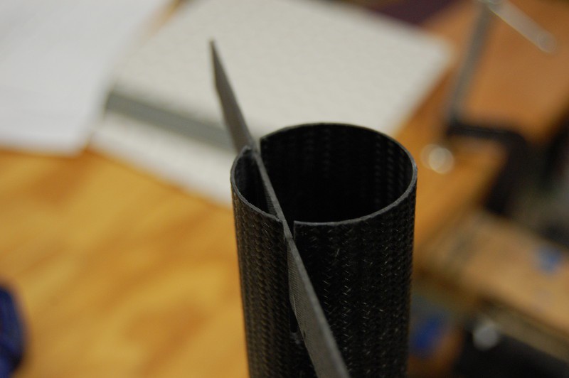
Including the angle of the 1.6mm reinforcing gusset, I needed to cut four ~2mm wide slots into the 40mm tube. Both of the tools I'd used previously--the carbide hacksaw blade and the diamond impregnated jigsaw blade--had kerfs thick enough to cause issues. As such, I opted to dull up a hacksaw blade instead. I built a quick jig to keep the saw between the lines on either side:
Then sanding. Lots of sanding. Many grits and paper configurations. I taped the inlet of my vacuum cleaner to the bottom of the tube to suck up dust during this part:
Many fit checks on the sanding. I needed a consistent 30mm-long slot. This took time:
This was a big moment. I used a pair of gussets that still needed to be glued to the pitch ring to test clearance between the two slots. It was close enough that I was able to friction fit the joint together; the two square tubes are unsupported in this photo, held in place entirely by the clamping force of the two gussets:
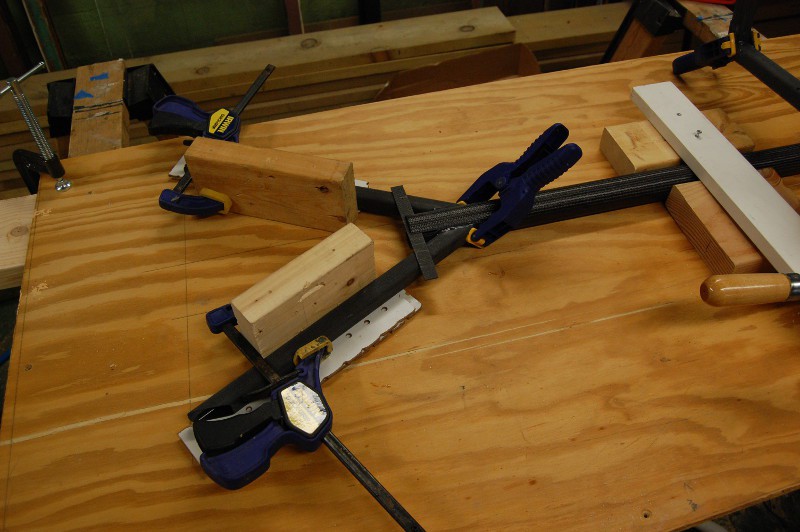
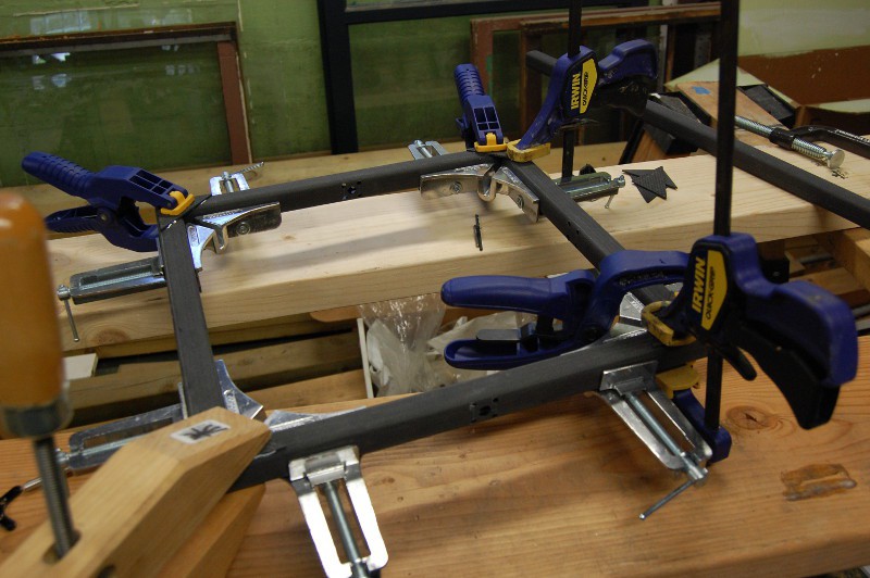
Time for gluing. This picture also gives a better overview of the alignment jig (the 2x4 scraps are all screwed in the from the other side of the plywood):
Close up of the joint, showing a piece of 1.6mm CFRP being used in the top slot to ensure rotational alignment of the 40mm tube. It was tempting to overdue the glue fillets, but I'm guessing they're something of a peel liability if they get too big:
Another view of the glue joint. I'm happy with how this turned out.
While I had the Space Glue out, I also adhered the remaining four triangular gussets to the pitch ring:
In a hilarious twist of fate, it seems that my previous assumption--that using square tube stock for the motor mount would leave me with enough to finish the project--was incorrect. I am 3" short out of an 8' section, so I'll be ordering more tomorrow along with longer screws and assorted other forgotten parts. Several work and house things happening this week, but with any luck I'll get a bit more construction work done Thursday or Friday evening.
- Zach
-
v09 build, part 1
07/26/2014 at 22:05 • 2 commentsToday I cut, sanded, drilled, and glued up the parts for the motor mount and pitch ring. I tend to cut pieces a few millimeters long and sand 'em to fit; this is especially helpful on the mitered joints. Tools that would be useful here: a tiny chop saw with a carbide or diamond blade and a drill press.
The first round of parts rough cut for v09. Not the nicest looking holes I've drilled (and subsequently enlarged a few times), but they will work:
Jigsaw cuts can be a bit rough:
Lots of sanding. PPE reminder, wear a dust mask and use a HEPA vacuum to clean up:
Ten minutes of sanding later, the angle is a bit better and the piece is the right length:
Shaft clamps fit, but will need longer screws:
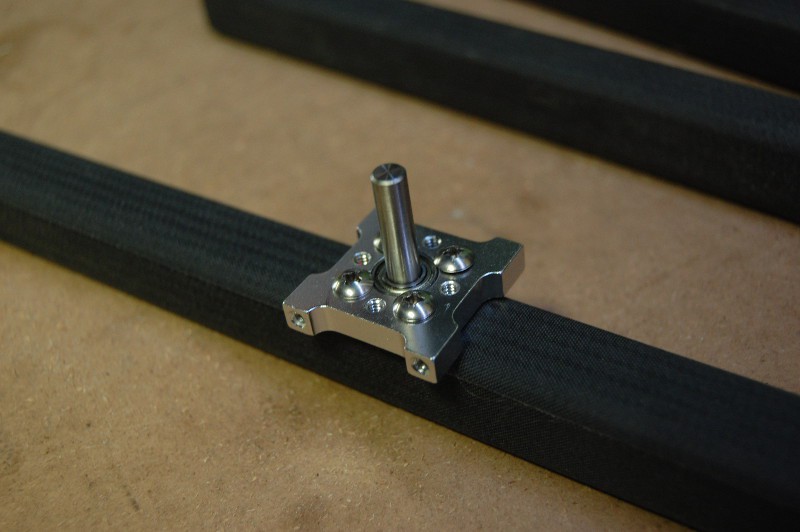
Bearing mocked up:
First gluing step for the motor mount:
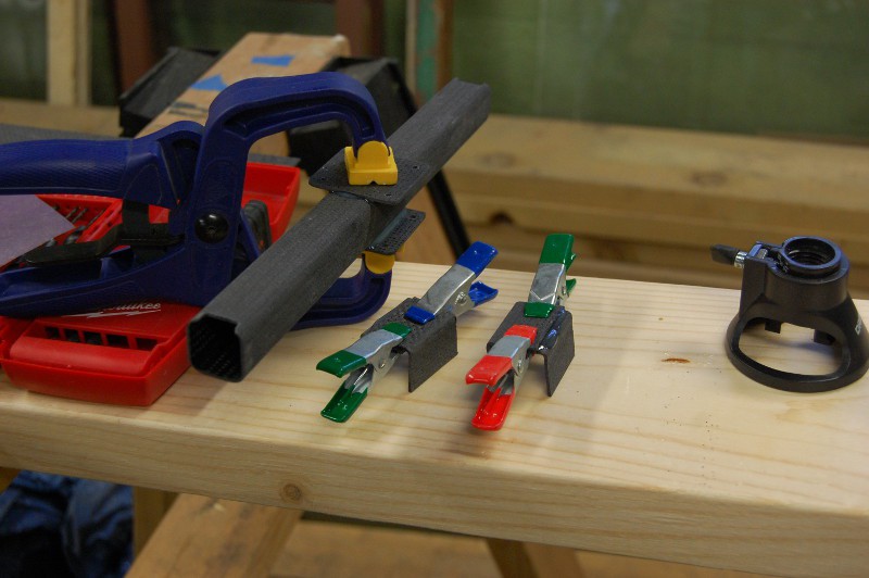
One can't ever have enough clamps:
Stay tuned, more to come!
- Zach
-
Last minute bits before the build
07/26/2014 at 01:35 • 0 commentsI know, I should hold off on this update until I've actually begun carving apart the 8' length of CFRP square tube sitting in my office. But I'm not going to get started on that until tomorrow, so I figured I'd post a quick update.
Lots of changes to the model; enough that I rolled everything into v09. Most things look the same unless you look closely, but a lot of dimensions changed slightly so it was a fairly lengthy process.
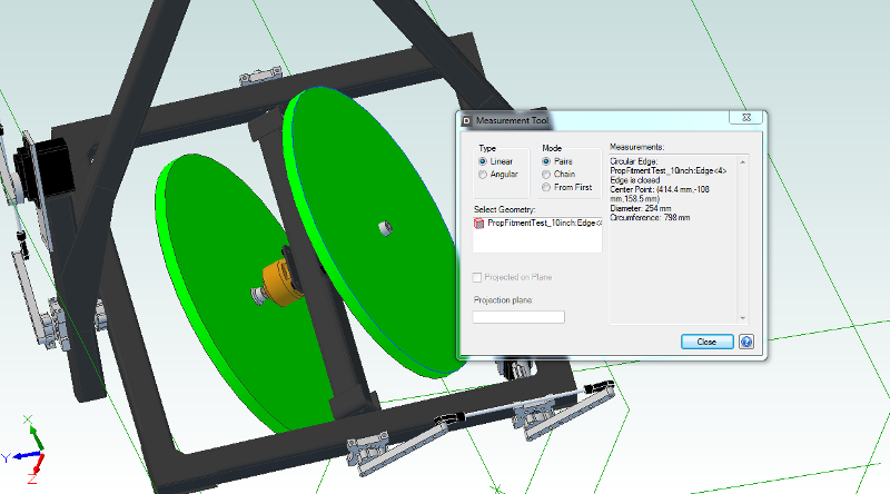
![]()
The picture above shows the measured diameter of the bright green prop stand-in disks: 254mm, or 10". Changes with v09:
- I tweaked the dimensions of the square tubing stock to reflect the stock I received earlier this week. Specifically, I had it in the model as 19x19 mm; in reality, it's more like 23x23 mm. I would have known this if I'd read the DragonPlate description a bit more carefully, I suppose. Lots of things were referenced to tube side walls, so this change pretty much affected everything.
- I increased the possible prop size to 10" in case I end up wanting to dial back RPMs (or go crazy with thrust). This actually didn't take much to do; I had to increase the width of the pitch ring, but the length was fine for clearance. That means minimal sub-frame modifications.
- The I-beam is gone, shelved for some future project. It's been replaced with square tubing as discussed in the last update. As part of that change, I also eliminated a few brackets previously needed to attach the beam to the shaft collars.
- I mitered the pitch ring ends, because why not? A bit more surface area for Space Glue, plus it looks better. Gussets provide most of the strength here either way.
- The larger-than-expected tubing had a handy side effect--I was able to get rid of the plate adapters that previously held on the bearings and shaft collars. Less cutting is good.
- Overall, weight didn't change by much; still well under 1.9kg.
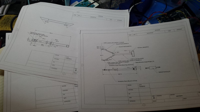
In preparation for the build, I also broke down the sub-assemblies into drawing packets. They're hastily dimensioned and have minimal notes (such as material, tolerance, stuff like that), but they'll make construction a lot easier:
![]()
The drawings are located in the same folders as their respective parts (under /hardware/v09); they share names with the parts they represent, minus the file suffix.
Enough stalling. Prototype build starts tomorrow!
-
CFRP arrived, build starts this weekend!
07/24/2014 at 12:09 • 0 commentsEverything arrived, including the 8' long tube stuffed with bubble wrap and CFRP square tubing. Exciting! Two CAD model changes to make prior to getting out the carbide-tipped jigsaw and Space Glue:
1) I'm going to increase the width of the pitch ring to accommodate a pair of 10" propellers. I re-ran a few thrust calcs and realized that at a hover, I'll need to spin over 10k RPM. This may be fine; my new ESCs are high-res units, so I might have decent control despite the relatively high kV of the motor (1350). However, I'd like the option to reduce RPM by increasing the prop diameter. Shouldn't add too much weight.
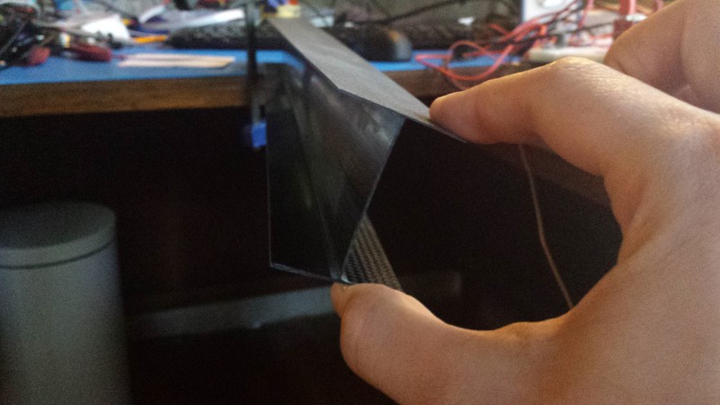
2) The CFRP I-beam, while totally awesome, lacks torsional rigidity. It's plenty stiff if you use it to span a gap and apply a static load, but it's made of pretty thin stock. I clamped the whole 2' length to my desk and applied a bit of a twist at one end to demonstrate:
![]()
It didn't take much force to deform the beam 15+ degrees. That's not good for my application; I need to be able to quickly rotate the beam from one direction and not have it deform too much. As such, I'm going to swap the I-beam out for square CFRP tube stock; I've got plenty extra from the shipment, it's stiff, and (as an added bonus) it will cut down the prop-to-prop spacing by around 30mm.
Stay tuned! Next update should include the start of the first physical prototype!
-
Why servos can get a bit spendy
07/20/2014 at 13:59 • 0 commentsI'm impatient for my CFRP to arrive; in the meantime, I wrote a quick program to test servo actuation speed. Pretty much "go to 90 degrees, wait 200 milliseconds, then go to 0 degrees, then wait 200 milliseconds". Repeat.
Results, comparing the Hitec HS-8360TH to a JR Sport ST47BB I had lying around:
Yup, I think I'll use the fancy ones.
-
CoM, prop clearance, and BOM
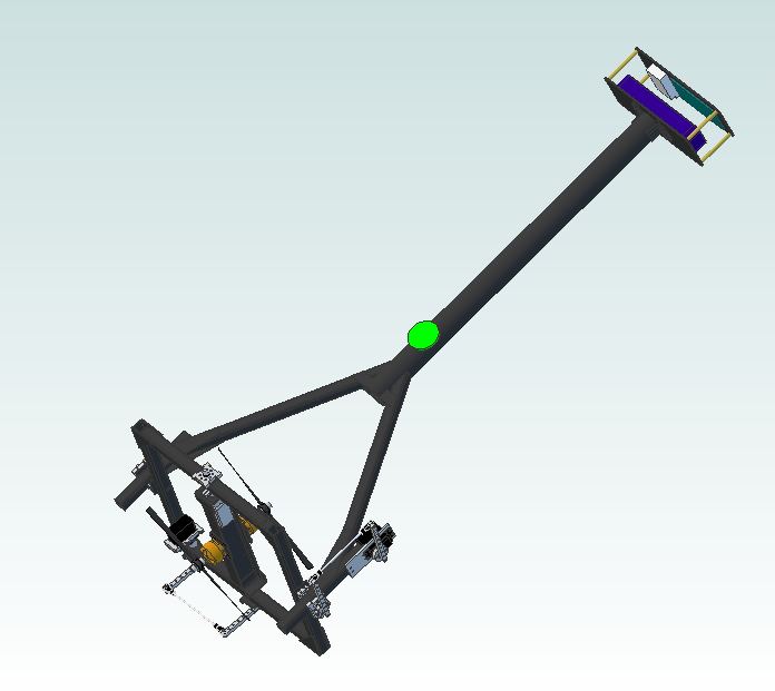
07/19/2014 at 21:24 • 2 commentsI calculated GimbalBot's center of mass and temporarily added a bright green disk to show its location on the model:
![]()
I'm happy with that. During stabilization corrections, the craft will rotate roughly around that point. As was discussed at the beginning of the project, it's important to keep the CoM above the CoP (center of pressure).
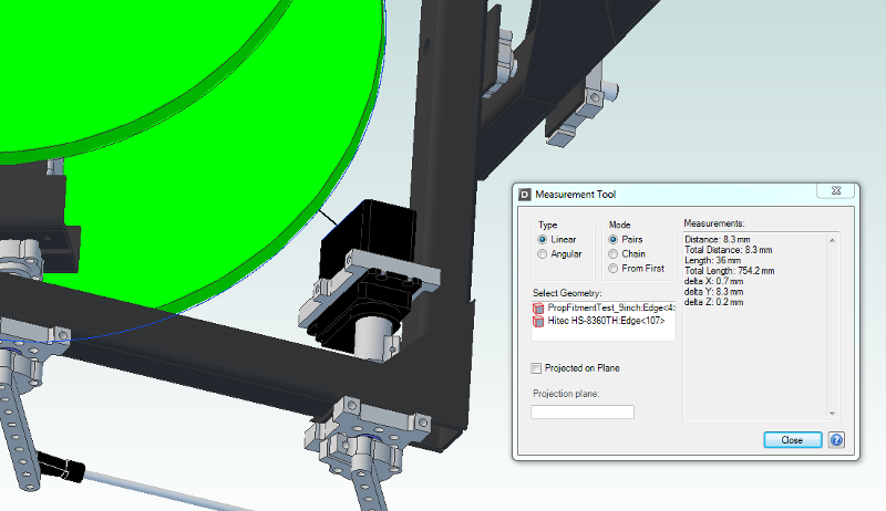
I also took Dave's suggestion and double-checked prop clearance by temporarily replacing the CFRP models with--you guessed it--bright green disks:
![]()
The screenshot shows the closest I get; roughly 8mm from the inner servo at 15 degrees inclination or so. I'm not worried about that. Furthermore, I verified that both axes can swing freely through 120+ degrees, so the servo's built-in 90 degree limitation will work fine for end stops.
I also added some gussets and a model of the servo power supply. The supply (called a Universal Battery Eliminator Circuit) adds about 50g to the model; I'm still under 2kg, so I'm also not worried about that (and the weight is up top, which is great). The new brushless motors/ESCs arrived as well, so I measured 'em up and updated the model. Everything still fits nicely; sadly, the new ESCs aren't bright yellow. Boo.
I finally updated the BOM to include v08 stuff; other than weight (which I'm calculating using the CAD model), most of the bits beyond nuts and bolts are included. Everything other than the CFRP is priced, too. I'll dive in to project finances at length down the road; suffice it to say that I'm paying quite a bit extra to get the best stuff I can get my hands on (well, not the best, but still pretty good). I'm hoping that GimbalBot 2.0 includes some major cost reductions and optimizations to make the platform more accessible to the hobbyist crowd.
All of the CFRP should be in early next week, and then construction can (finally) begin!
-
parts parts parts!
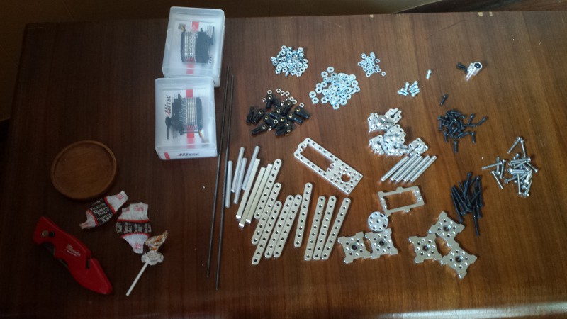
07/17/2014 at 20:52 • 0 commentsOkay, so this update isn't terribly worthwhile. But the first of several orders arrived today! Mechanical goodies and some pretty serious looking servos:
![]()
And yes, the candy arrived with the order and was eaten whilst unpacking the various packages. Thanks, ServoCity!
-
9 axes of data, plus a few reinforcements
07/17/2014 at 04:00 • 1 commentLots of stuff shipped today (including the CFRP stock!!), so this evening I decided to dig into a few things on the list.
Sensor data
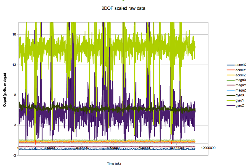
I wrapped up the functions for pulling data out of the magnetometer and gyroscope. Other than the Y and Z gyro axis (which are extremely noisy), everything looks good:
![]()
Code is in the Dropbox repo under /firmware/ArduinoDue/_9DOF_test3. I'd love some help on a few things:
- If you dig through my code (_9DOF_test3.ino to download the Arduino source code, or _9DOF_test3.c to view the program in a browser), you'll see that I had to putz around quite a bit with two's complement conversion to pull integer data out of the three sensors. The accelerometer uses a 10 bit ADC, while the magnetometer's ADC is 12 bit and the gyro is a 16 bit device. There has to be a more efficient way to turn those byte pairs into useable signed data. Any thoughts?
- Why are channels Y and Z of the gyro so darn noisy? I guess in the grand scheme of things they really aren't too bad; for the gyro, the Y axis is scaled in deg/s and they're scaled 0-2000. Okay, so 0.5-1% noise. Alright, maybe that's within spec for the instrument. Even so... why is the X axis so clean in comparison?
- Everything else looks nice. I'll run some analysis on this data like I did with the accelerometer data previously to get a picture on noise normalcy. Still clicking along at over 300 samples/second, which is faster than the magnetometer spits out data.
Reinforcements
These aren't finalized by any means, but I added a few reinforcements to some of the joints in v08. First, some 5mm chunks of angle stock to beef up the battery plate connection (you can see the Arduino Due model, too):
![]()
Next, a few strips of 1.6mm CFRP plate for the main tube joint:
![]()
... and a few triangular gussets near the pitch ring bearing mounts:
![]()
As Dave suggested in a comment several days ago, I need to re-check pitch ring range of motion vs propeller interference again, especially with the new gussets.
More to come. Comments welcome!
- Zach
-
Got excited, ordered parts.
07/15/2014 at 16:15 • 0 commentsEverything has been ordered to build v08:
- CFRP: square tube, I-beam, angle, and various plates.
- Brushless motor stuff: higher wattage motors, ESCs, and spare props.
- Servo stuff: Servos, mounts, linkages, bearings, shafts, etc.
- Electrical bits: Battery (the 5000mA was in stock, so I grabbed it instead), wire, small power supply for the servos, battery alarm, etc.
I'm guessing the CFRP is the furthest out; with any luck, the stock will ship Friday for delivery late next week. While I wait, I'll work a bit more on instrumentation and software.
Welcome to Stoked-ville, population Zach.
-
Ordering parts in a few days!!!
07/14/2014 at 03:14 • 8 comments... and I'd love your feedback. Seriously! This is design iteration number 8, and I'm ready to lock it down and put in a major CFRP order. I'm planning on sleeping on this and maybe tinkering a bit more tomorrow or Tuesday, but I don't want to make many more changes. Time to build a prototype.
A few quick (and rough) specifications for v08:
- Weight: 1850g
- Thrust:Weight Ratio: 1.5:1
- Estimated Battery Life: 6-8 minutes
![]()
Okay, so what's new? Be brief, Zach!
No more reaction wheel. I've gone in to depth on this decision previously, so I won't belabor the point here; needless to say, this choice makes a lot of things simpler and lighter:
- No more slip ring
- No more power converter
- No more large hollow shafted brushless motor
- No more additional brushless motor controller
![]()
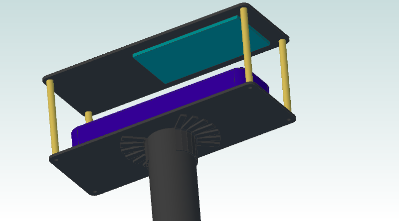
See? Isn't that a simpler battery compartment? Also notice the largeness of the battery; I'm using a 3S 6000mA unit. The Arduino and various other bits will mount to the underside of the top plate.
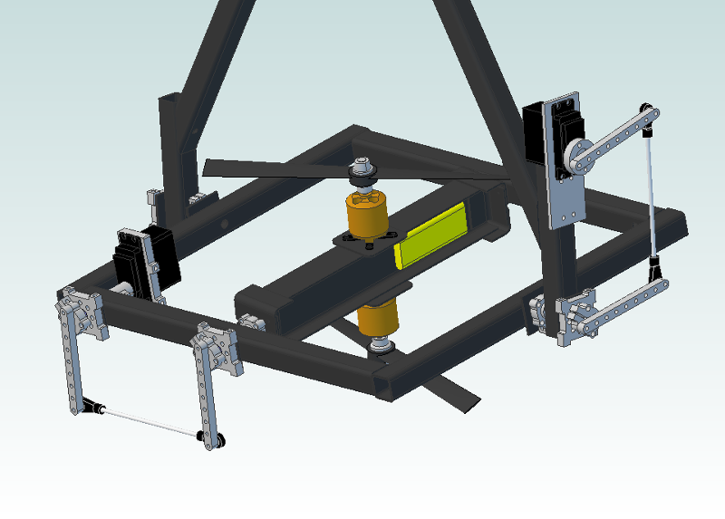
Back to the original X/Y thrust vectoring design. It's somewhat proven and should dramatically improve reaction time (again, see the previous post; I'm talking 50 Hz vs 6 Hz, so nearly an order of magnitude improvement. At least on paper...).
![]()
Yeah, I know the linkages aren't quite parallel... I got a bit lazy with my measuring. Stuff to note here:
- All of the aluminum bits are Actobatics parts that I can get easily. The models should be fairly accurate assuming the drawings are good on their site; the parts are likely a bit lighter than estimated since I didn't include all of the holes. K.I.S.S. is in full effect here; I could shave some weight off by custom machining stuff, but I don't have a machine shop. These parts are all in stock.
- Linkage arms are long for a reason; I can't find a reliable spec on servo resolution (most stuff I read online for the digital units seems to be in the 0.25-0.5 degree range). If resolution and chatter prove to be an issue, I can adjust the linkage ratios down a bit; conversely, I can also speed things up a bit if the servos are beefy and accurate enough. Either way, I'll probably hand-trim the linkages after figuring out which holes are best.
More power!! You noticed that thrust:weight ratio, right?? Yeah, I'm hoping to see maximum thrust in the 2.8kg range. How?
- 9" CFRP props (already on hand, and in the model)
- 1350kV/400W motors (not in the model, but similar in size and weight)
- 50amp+ ESCs (also not in the model)
Back-calculating from the prop thrust tester, I'll need ~10k rpm to hit 1.8kg thrust at about 170W/motor. Given 80% motor efficiency and a bit of extra power draw from sensors, controllers, servos, etc, I'm estimating average power consumption at 500W or so. 6000mA 3S battery-->66W-hr capacity-->8ish minutes of run time at a hover. I'll take it, even if it's half that figure in reality.
Stuff that isn't shown (but is included in the weight estimate)
- Arduino Due
- 9DOF sensor stick
- Motor tachs
- Wire and connectors
- RC stuff (this likely comes later)
- Gussets/plates for the CFRP square tube joints
- LANDING GEAR!
More to come early this week. Comments welcome!
- Zach
GimbalBot
Gimbaled thrusters, aerospace-grade adhesives, carbon-fiber-reinforced polymers, and inertial measurement units. This is a space project!
 zakqwy