-
Further iterations. Time to finalize the design?
07/13/2014 at 01:30 • 0 commentsI took a bit of time away from GimbalBot to spend time up north and to think about the basic craft design. There were a pair of loons at the lake that had a few babies. PSA: baby loons are damn cute. Glad I had a decent pair of binoculars on my Christmas list (thanks, Mom!). Note to self: hanging out with baby loons helps one to see the big picture.
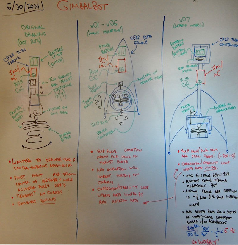
Technically, the following drawing (taking up the left 60% of my office whiteboard) was produced prior to the last project log. My bad, I've been holding out:
![]()
A few notes:
- Not relevant to the drawing content, but taking a picture of my whiteboard is a bit of a pain. I usually photograph it in the evening; my office has south and west facing windows, so the glare gets excessive between 6pm and 9pm during the summer. The above drawing has a bit of global brightness/contrast tweaking and local brightening/darkening to improve legibility; additionally, I took the picture at an off-angle so it's de-distorted. Apologies for the lack of clarity!
- Left pane: original drawing (Oct 2013)
- This is a pretty straightforward copy of the original sketch I had in the Project Idea Diary. Some kind of hollow CFRP frame, either a tube or a truss. A commercially available contra-rotating system that spins the props from one end using a hollow shaft. Servos for X/Y tilt control.
- It seems dumb, but the 'somewhat boring' comment still stands. The off-the-shelf contra-rotating propeller assembly requirement really pushed this design to the chopping block; I couldn't find good thrust data online but I think those units are generally sub-kg systems. In any case, I moved on from this concept before actually estimating thrust::weight ratio using a CAD model, and never built in a landing system or really gave the servo linkages much thought. I would have run into issues with the inner ring servo, since rotating the outer ring would affect both angles.
- Center pane: v01-v06 (end of April 2013-Juneish)
- Many revisions here, as noted. All of them used a 'flat-pack' style CFRP frame, ideally waterjet cut from large-dimensioned 1.6mm stock. Switched to a polar thruster design using a slip ring; at some point I did some electrical calcs and realized that I'd need to deal with voltage conversion. Converter located on thrust plate. Thrust:weight ratio in the 1.3-1.5:1 range.
- Got concerned with cost; large CFRP plates aren't cheap, and the waterjet work would have been pretty expensive too. Also, once I thought about the torque effects from the thrust plate I decided to change the design substantially.
- Right pane: v07 (late June)
- The last full CAD model. Reaction wheel using the battery packs, slip ring and rho control (now a brushless hollow-shaft motor) mounted up top to improve weight distribution. Thrust:weight ratio around 1.3:1 or so.
- Had a few issues, highlighted on the board:
- 6Hz max update rate if corrections are 90 degrees off from each other (worst case scenario). Limited by slip ring.
- Brushless motor is heavy and draws a decent amount of power (probably). Also needs a controller.
- Thrust:weight of 1.3:1 assumes pretty optimistic thrust output. Remember, I was driving the ESCs at 16vdc or so... still didn't know if 12vdc would give me enough thrust.
- Real talk: Had some issues with the power converters (see previous post). Got a bit discouraged and had to walk away for a brief period. I'd say I've got a pretty good chance of getting the remaining unit to work (especially if I seek support from GE), but it was time to move on.
- Slip rings and matching hollow shaft motors are surely useful for other stuff. I'll put the power converter in my rarely-used-but-valuable parts bin and get it out when I've got an application in ten years.
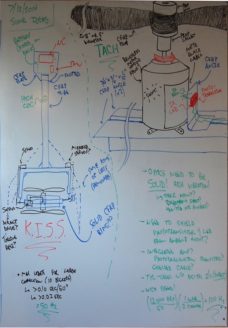
So. Like I said, I had a bit of time to think. I tried to distill those thoughts into another whiteboard drawing:
![]()
- Left drawing: GimbalBot v0.8
- Ditched the reaction wheel and used a fixed plate for the battery and uC/IMU mount. Bam, saved 250+ grams.
- No more rho/sigma control; back to X/Y. 6 Hz --> 50 Hz update rate using the servo/correction angle assumptions shown.
- Propellers face away from each other. Brings more weight in while pushing thrust out a bit; not sure how this will affect overall thrust output but I'm willing to bet it's not by much. Dramatically simplifies the thruster design.
- Servo linkage ideas shown but not really developed; I'm going to save that for the CAD model. A few thoughts on this:
- I want to balance the weight and avoid torque across the rotated structure, so two servos is an appealing solution; however, I'm a bit worried about syncing them up, especially when I first turn the system on. Don't want them to fight each other. Might want to build a shaft of some kind. Could use the shaft as an adjustable torsion bar to eliminate backlash... hmmm...
- Direct drive could be cool to eliminate backlash further, but servo mounting might be tough (and wide).
- Can I build the ring from a section of large CFRP pipe? Does that stuff exist? Could I use a foam tube wrapped in CFRP and resin? Do I want to get in to CFRP fabrication? Time to do a bit of research. Not the end of the world if it's square.
- Torque calcs are a good idea for the servos. Maybe I'll just assume I'm lifting the whole structure from a static point? Should I calculate maximum torque as if the pitch ring is rigid with respect to gravity and the servos are lifting the rest of the structure? Realistically, I don't need more than +/- 10 degrees off the gravity vector.
- Need a landing system that can be broken down and stored, maybe inside the frame tube. GimbalBot should be able to travel.
- K.I.S.S.: Keep It Simple, Stupid!
- Right drawing: Tach
- Realized that I'm currently planning to use the vertical accelerometer axis as the input to the thrust control loop (the one that keeps the craft vertically stabilized). If I can accurately measure RPM of each motor and build a table that relates those values to acceleration readings from a test run, I can use RPM differential and individual motor speed as a leading indicator for both the longitudinal axis' rotation and the vertical acceleration. Feed forward control, just like a fancy boiler!
- 100 Hz acquisition is easy with a decent detector. Need to run some tests on the motors with matte paint to be sure my signal is clear. Ideally, the processing circuitry between the phototransistor and the Due's digital inputs is minimal. Might need something similar to a debounce algorithm in software to kill noise, or something in hardware.
- Shielding? Maybe felt, or something else flexible and glued on to the CFRP angle? Ambient light = bad. Also, shielded cable to avoid EMI from the ESCs.
- Might want to mount the tach bracket to the frame using vibration isolating bumpers. I've got a pile of HDD shock bumpers somewhere in the basement from a recent PC build, those might work. The area around the motor gets pretty crazy at full power.
Dinner time, then I might hit CAD a bit tonight to start v0.8. Hoping to finish the model tomorrow afternoon and get parts on order so I can start building. I would love suggestions and comments over the next 12 hours or so; as the title of this post indicates, I'd like to finalize the design and get crackin' on a prototype!
- Zach
-
Safety first, kids!
07/03/2014 at 16:31 • 0 commentsI try to be safe when I mess around with electronic stuff. I've been in various industries long enough that constant PPE use is now the norm. Definitely a change from my youth; I remember using a 6kv/30mA neon sign transformer to figure out my concrete driveway conducts electricity. When I walk in to my workshop, step one is donning a good pair of safety glasses. Ah, foreshadowing...
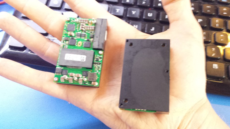
In any case, the power converters came in and I picked 'em up yesterday. As expected, they're TINY:
![]()
I wired one up through the slip ring, charged up the LiPo batteries (16S configuration!), connected everything to a 12vdc LED strip, and grounded the 'on-off' terminal to power the unit on. And.............. nothing. I measured a bit over 60vdc across the power terminals which is above the unit's spec, so I disconnected a battery and shorted its terminal to get around 49vdc (on the low end). Still nothing. Hmmm...
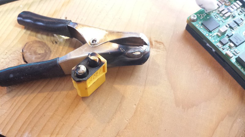
Mistake #1: I didn't fuse the input supply. Quite stupid, I know; I was in a rush and didn't have a spare 25amp fast-acting fuse lying around. I thought I might have misread the datasheet (I was really pulling at straws at this point), so I reversed the input polarity on the converter. That was mistake #2:
![]()
As we all know, high-performance LiPo batteries don't mess around. These are rated at 50c maximum discharge; they're 890mA units, so they're DESIGNED to sink up to 45 amps or so. Do the math at 60 volts; that's a lot of power!
In any case, I took a break and thought about how stupid it was to not fuse the battery system, given that I'd just vaporized a hole in a large alligator clip (and a good portion of the brass terminal disappeared). I checked the datasheet for the tenth time and realized that the on-off circuit should show 8 volts or so to ground; I only measured 3 through the slip ring, so I decided to run a direct link from the on-off terminal back to the power converter (hoping I could offset any voltage drop I was seeing across the small-gauge slip ring wires). Which brings us to mistake #3:
![]()
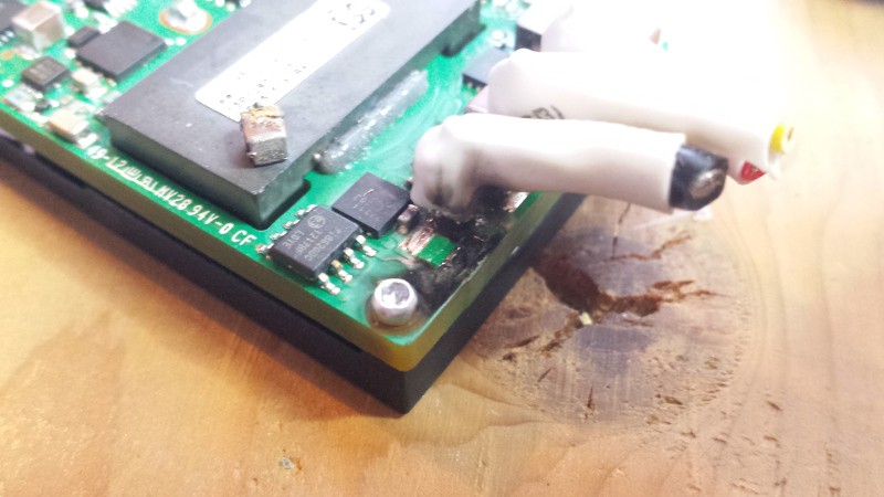
I spent a lot of time carefully soldering the power leads (now cut off in that picture) to the board and heat-shrinking them; then when I wanted to bypass the slip ring, I tried to manually short the yellow switching lead to the exposed part of the negative terminal post. Naturally, my hand slipped a bit and the wire touched the surface mount capacitor on the board. The cap fried, the trace vaporized, and one of my converters is now toast! I pulled the cap off (you can see it on top of the metal heat sink in the picture); I might be able to replace it, but the trace is pretty badly damaged.
In any case, I'm headed out of town again for the holiday weekend. With luck, I'll read the datasheet again next week and realize that I'm hooking the converter up wrong. I might put in a call to GE too, since I don't want to risk frying my second (and last) converter. And yes--I'll order and install an inline fuse holder. Stupid, stupid, stupid.
- Zach
-
Accelerometers are normally noisy.
07/02/2014 at 02:04 • 2 comments![]()
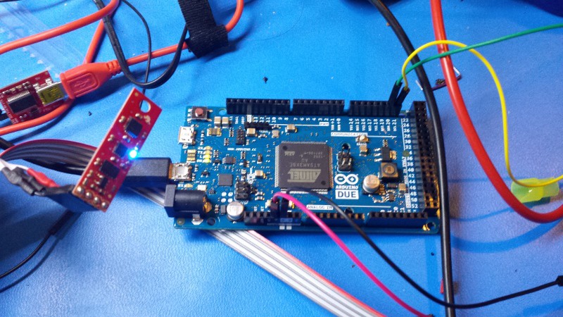
Switching platforms was a great call. I got back from a relaxing North Woods weekend and an Adafruit package was waiting; the Due hooked right up after getting my hands on Arduino 1.5.6-r2 (you need this version for Due support). I wired my 9DOF stick up to the I2C bus (in my case, SDA is comm line 20 while SCL is comm line 21), grabbed a demo program mentioned in the product comment section, and tried displaying some data on the serial debug window. It took a bit of putzing (getting addresses right, re-restarting serial communications, that sort of thing) but I got it working; a live data stream showing raw integer values for the accelerometer, gyroscope, and magnetometer. Code is in the dropbox repo under /firmware/ArduinoDue/_9DOF_test1 (click the c code link if you don't want to download the Arduino file).
Getting a data stream set up was great, but the actual values didn't make much sense. The accelerometer's datasheet suggests the device features a 10-bit output; since it's signed, that means I should see integer values between -512 and 511, scaled to +/- 2g (this is selectable during initialization). However, I was getting wild results; sometimes I'd see reasonable numbers in the teens or low hundreds, but turning the board upside-down would make the value hover a bit below 65536. Hmm.. that's 2^16. Seems like we've got an issue with the data type conversion.
The ADXL345 dumps raw data through a pair of bytes for each axis, marked n0 and n1 (where n is the axis, x/y/z). By default, the output is in two's complement format; this article provides a great overview of that concept and talks about how one can do various conversions . In any case, the Arduino compiler is supposed to convert signed two's complement bytes into signed integers automatically using the int() function, but I'm guessing this didn't work right because these are 10-bit values. The ADXL345 is also set up with sign extension, meaning everything to the left of the most significant bit (the 10th, which represents sign) is the same as the most significant bit. Time to modify the function a bit.
I took the _9DOF_test1 program and pretty well gutted it; at this point, I've only messed around with the accelerometer so the magnetometer and gyroscope portions have been removed. I kept [petmar0]'s Wire() calls intact to buffer data from the sensor, but changed how the two bytes are combined to properly convert the two's complement pair to a signed integer. I also took out a few program delay functions and cranked the baud rate up to 115,200 bps; I want a lot of fast data to get a better handle on noise. Take a look at this completed program at /firmware/ArduinoDue/_9DOF_test2 (again, click the c code link if you don't want to download the Arduino file).
I used gtkterm to dump a bit of data from the accelerometer; in the _9DOF_test2 folder, you'll see a few text files with various names related to 'data dump'. The only one I've taken a close look at so far is the file marked 'NoShaking', where I just left the chip on my desk and let it record noise. Note that the files blew up to ~100kb+ in a matter of seconds; I calculated my acquisition rate at 340 samples/second. Speedy!
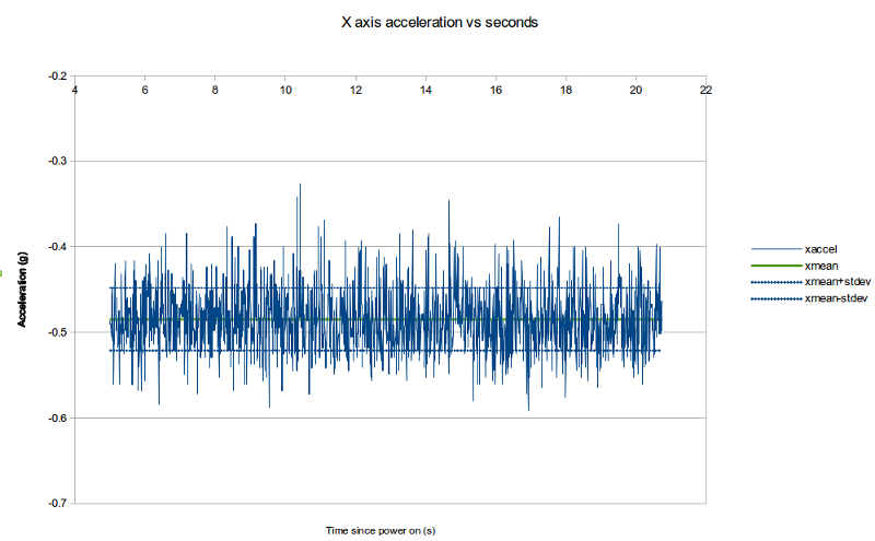
The spreadsheet [*.ods file] in the _9DOF_test2 folder shows a bit of quick data analysis. For clarity, I changed microseconds to seconds and divided the acceleration values by 256 to get floating point 'g' values. Then I plotted the x record against time:
![]()
The blue dotted lines are standard deviation, while the green is the mean. Note the y-axis range; the standard deviation is roughly +/- 0.03g, which isn't bad!
Kalman filtering assumes the data follows a Gaussian distribution. I didn't run any normality tests, but I did put the data into a histogram to get a feel for its shape:
![]()
Looks pretty normal to me, I'll take it. For the stats folks:
xmin: -0.592 g
xmax: -0.326 g
n: 5362
bins: 64
sigma: 0.037
xmean: -0.485
rate: 340 samples/sec
Still to do: take a look at the accelerometer movement records, figure out the magnetometer and gyroscope interface (they also appeared to exhibit the two's complement conversion issue), and start thinking about Kalman filter implementation.
Comments more than welcome--I'm not great with bitwise stuff and I'd like to make my code as efficient as possible. Let me know your thoughts!
-
Changing platforms.
06/26/2014 at 23:35 • 2 commentsTL;DR: STM32F4+ChibiOS/RT --> Arduino Due, because I need to keep moving.
In my 29 years, the biggest challenge I've had with projects has been staying motivated. That's why GimbalBot is on HaD.io; chasing a silly prize is a great bonus, but I'm hoping that staying in the public eye will keep me moving forward. I don't want to dig through my closet in ten years and find a half-glued carbon fiber frame with a few sad blinking LEDs; I want to follow this one through to the end. If you've made it this deep in to the project logs, I'm guessing you've experienced the same thing (or else it's you, Mom, and you remember the piles of half-finished circuits in the basement). After all, there's no better way to procrastinate coding a difficult control loop than to get lost in an insanely long build thread.
So what affects project motivation? What pushes us to stay up past midnight on a weeknight, hammering out circuit board designs and building BOMs? Why do we stay at our soldering irons when the other kids run outside to hit things with sticks?
Forward progress is key.
Or at least the feeling of forward progress. I often sit down and work on GimbalBot for a few hours after work, or after breakfast on the weekend... and I like it when something happens each time. It can be minor, like a few tweaks to the CAD model or soldering up a few power connectors, or it can be major, like a successful prop thrust test. Or I can work on something for a few hours, have it not work at all, toss it in the trash, and put together a plan for fixing the problem during my next work session. That's still progress.
So what happened? Why did I get all philisophical on you, my imaginary reader base? I've stalled with my code. Between last weekend and most nights this week, I've probably got 20+ hours in to the STM32F4+ChibiOS/RT platform without much to show for it, and I'm ready to cut my losses and move on. It may seem like I've made progress--well-tailored build logs can create that illusion--but I really haven't. I need to get a basic serial debug system set up and the inner workings of the firmware have thus far eluded me, so I'm stuck pasting together demo programs and helpful (but not always compatible) projects from the greater Internet. It's gotten to the point that when I google 'ChibiOS' or 'STM32F4' along with 'USB', 'Serial', 'I2C', or any of a number of other terms, all of the links are purple. Even on the second page. Not a good sign.
Why? Well, I took a class in C++ a number of years ago but we really stopped short of the advanced (intermediate?) stuff. Dealing with pointers and casting variables makes my head spin a bit, and I haven't had much luck figuring out what makes the program tick by studying gobs of publicy available source code. I should point out here that Giovanni Di Sirio has done an amazing job developing ChibiOS/RT--no small feat for a team of paid programmers, let alone a single guy working on an open source project. But he didn't develop the OS for newbies; it's a robust, compact, efficient platform for experienced developers. Which brings me to a humbling point I've danced around for many years...
I'm not a programmer.
Maybe I should say I'm not a good programmer, or I'm not an experienced programmer. But it's just not my specialty, by a long shot. To be fair, I'm not a CAD modeler either, but I can fake my way through that (at least for the basic stuff I putz around with). I can piece things together from old programs I've written with a lot of help, but I need a lot of help because it's not something I do every day. As such, I've decided to transition GimbalBot from the STM32F4+ChibiOS/RT platform to the Arduino Due. The Due (which I haven't used in the past) features an ARM Cortex M3 32 bit processor and plenty of I/O, so I'm not worried about it handling my computational requirements; I'll miss the convenience of multithreaded development, but realistically my application will be fairly simple and broken in to discrete functional blocks.
So what's the lesson? Simple: I need to keep my pride in check. I started playing with Arduinos a number of years ago and eventually decided that I'd "graduated" to the big leagues. Some of this is because I read plenty of forum posts decrying the 'Duino's sometimes frustrating IDE, or its limited capability compared to dedicated processors, or, or, or... in any case, it's more than suited for this project and switching over will remove a MAJOR frustration point.
Thanks for letting me vent.
Don't worry, normal posts will continue early next week. I'm headed up north this weekend, but the Due (along with the power converter, hopefully) will show up next week so I can get crackin' on Kalman filters!
-
Serial Output
06/25/2014 at 23:32 • 0 commentsSo... I'm not much of a programmer. I can hammer code together when I need to, but ChibiOS/RT is proving to have a steep learning curve. Most of what I've done to date has involved hacking apart existing code. For example:
I tried writing a more stand-alone program, but I had trouble getting my computer to recognize the board without the demo program's shell routine. Not quite sure why, but this will work for my purposes. As I mentioned in the video, the next steps are getting the I2C IMU running, increasing the data acquisition rate, grabbing the captured data, characterizing the sensor noise, and implementing a Kalman filtering routine to fuse the sensor data into proper angular orientation information.
Code is in the Dropbox repo under firmware/DemoProgram06242014-chibiosUSB. Suggestions welcome--this is new territory for Zach!
-
Zach's first ChibiOS/RT program!
06/22/2014 at 21:50 • 0 commentsIt's really not my program; I just played around a bit with the demo code on that awesome Recursive Labs Blog post I mentioned yesterday. Nothing too fancy, I mainly added a few threads so the four LEDs would flash independently:
The program is designed to emulate out-of-sync turn signals at a stop light, as discussed in an old xkcd:
![]()
(original link to xkcd's page with the above comic)
The program is in the GimbalBot Dropbox folder under 'firmware'; if you're bored, take a look and let me know what you think.
-
STM32F4Discovery + ChibiOS/RT
06/21/2014 at 21:15 • 0 commentsIt's a beautiful day here in Minneapolis, so Danica (my wonderful and extremely project-accomodating wife) and I took a bike ride to check out the near-flood-stage Mississippi:
![]()
Yup, they've opened the locks up at St Anthony Falls to let the excess water through. Wettest year on record to date. Glad I live on a hill. In any case, a great outdoor morning made me feel better about spending the afternoon putzing around with my ARM Cortex M4 discovery boards.
I'm following these instructions to set up my development environment; I'm somewhat new to things like 'toolchains' and so forth, so it took a bit of trial and error. The PDF tutorial they linked has good instructions on building the toolchain and getting STLINK up and running. I'll try to outline my steps in detail here.
- I installed a GNU toolchain that supports ARM Cortex chips. The linked file was no longer supported but forwarded me here, and I followed their instructions for Ubuntu 12.04 LTS. Everything seemed to work properly.
- I installed STLINK, the open source program used to debug the discovery board. Pretty easy; clone the git repo and build it out using a few commands. I must have had the required dependencies already because it seemed to work properly!
- I grabbed the latest version of libopencm3, an open-source firmware library for various ARM M-series microcontrollers. Installation was easy with their instructions.
- I started up the GDB server, which is used to interact with the connected STM32 board. My board is an F4, so I've got ST-link/V2. Pretty easy to get this going, as documented in the *.pdf linked above:
- Use the ST-link/V2 command to start the GDB server: ./st-util
- It didn't work! Maybe I don't have the dependencies installed for STLINK; I need libusb-1.0, which I obtained by following the instructions here.
- Man, that didn't work either. libusb wanted libudev. 'sudo apt-get install libudev-dev' fixed that problem.
- Now I can install libusb. Good.
- Still getting the following error: WARN src/stlink-usb.c: Error -3 opening ST-Link/V2 device 003:012. hmmmmmm...
- It didn't work! Maybe I don't have the dependencies installed for STLINK; I need libusb-1.0, which I obtained by following the instructions here.
- Use the ST-link/V2 command to start the GDB server: ./st-util
- Okay, screw it, I'm going to start over and follow the instructions on the blog post also linked in the instructions. We'll see if that works.
- Seems like a great guide. It's a bit old, so a few things have changed:
- The name of the rules files is a bit different. I used v2, since I've got an F board.
- The full discovery board example project zip link isn't right anymore. I found a mirror here.
- 'flash' doesn't exist anymore; now it's 'st-flash'. I followed the instructions in Beneden's comment from 10/9/2013 and changed a few things. AND IT WORKED! I ACTUALLY LOADED A PROGRAM ONTO THE BOARD THAT WORKS!!!
- Seems like a great guide. It's a bit old, so a few things have changed:
- Next up: back to the original instruction sheet. Time to grab ChibiOS/RT and get the demo program online.
- I copied the STM discovery board code into a new directory and modified main.c as suggested on the site, then loaded it onto the board by typing 'make' then 'st-flash write build/ch.bin 0x08000000'. To quote stlink: "Flash written and verified! Jolly good!"
![]()
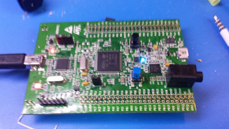
The blurry picture above doesn't look like much, but that blue LED is blinking according to the ChibiOS/RT program detailed on the Recursive Labs blog post. That's a huge hurdle crossed off the list: now that the dev environment works I can start writing code, and ChibiOS/RT has a hardware abstraction layer that will make syntax MUCH SIMPLER.
WOOOOOOOO! Next up: Interfacing to the IMU and figuring out Kalman filtering!
-
Soldering Tangent
06/21/2014 at 02:23 • 1 commentAs you may know if you have read previous project logs, I am currently working with a local rep to obtain a 60vdc-->12vdc 600w DC:DC converter. The guy was on vacation for a week but he got back to me yesterday and today to let me know that a few units are on the way. Extremely exciting bonus: the manufacturer is providing them as samples, free of charge. Not a bad deal, given the units are $225ish apiece in quantity. I'm quite fortunate to get this deal, so I'm making sure to account for that cost in the BOM.
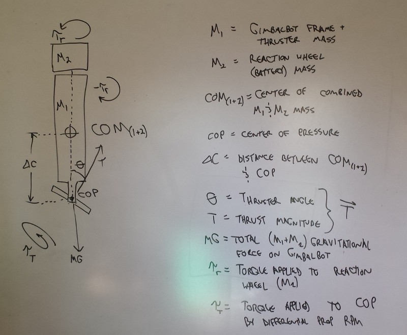
In any case, I'm holding off on other mechanical stuff until I can run thrust tests while powering the motors via batteries through the inverter. I want to figure out maximum thrust:weight ratio and also see how long I can operate at a steady ~1500g or so, as that will give me a rough idea of total flight time (well, minus power consumption by the theta servo, rho motor, and ARM...). I did draw a simple diagram of GimbalBot on my whiteboard:
![]()
(note: my whiteboard is pretty shiny and my office catches the evening sun, so you can see my green shirt. I'll get a better curtain someday.)
... then I decided to change gears and solder a few connectors, as I'll need them for the test. By the way--I'd love some advice on diving in to the physics; I didn't take any kinematics or controls classes, so I'm going on the stuff I learned in basic Newtonian mechanics and statics (and this project is distinctly not "static").
Soldering X160 Battery Connectors
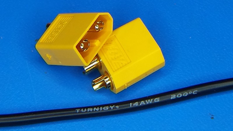
I did a bit of research and found that most of the batteries in the range I'm using (4S, 850mA or a bit bigger) use X160 connectors. I grabbed a few bags of male/female connectors along with some high strand count 14-gauge silicone insulated wire. The wire is super flexible, which takes a bit of getting used to; it feels like 28-gauge wire that's really heavy:
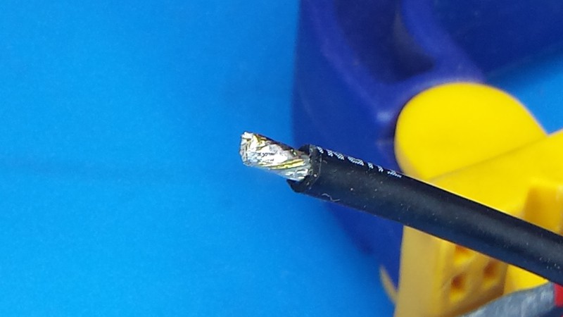
![]()
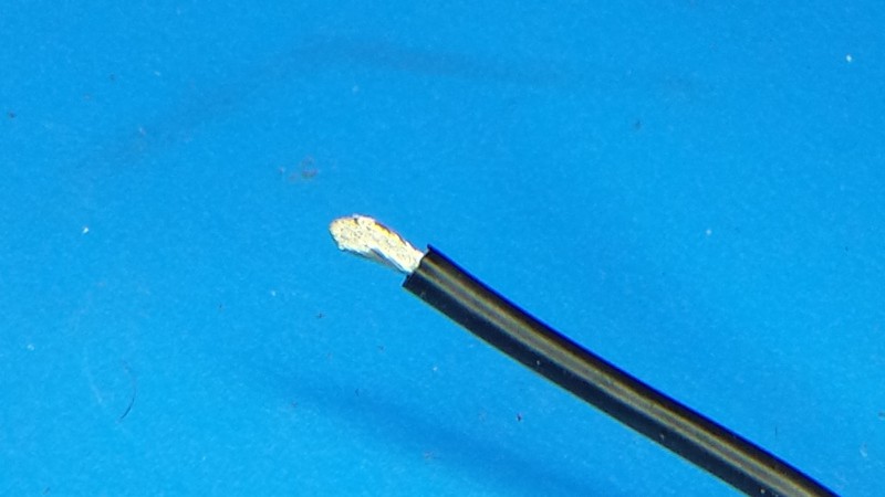
I stripped a bit of insulation off:
![]()
and then tinned the exposed wire:
![]()
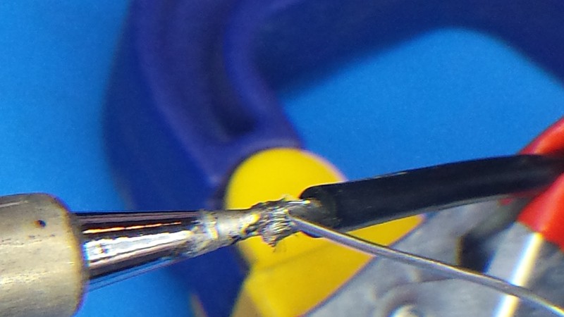
Not pictured: a dab of no-clean flux. My solder is cored with it too, but extra flux makes RoHS work a lot easier. I blobbed some on to the wire prior to soldering it.
![]()
I tinned the wire enough to nearly hide the strands. If you do the same, don't be afraid to trim off a stray wire or two; there are enough in the bundle that a couple missing strands won't matter for current capacity.
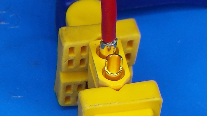
After prepping the wire, I set the X160 connector up in a makeshift vice (the red lead had been soldered earlier):
![]()
Nothing fancy, just a ratcheting hand operated clamp. I warped the casing on one in an earlier soldering run since I was holding it with an alligator clip-based helping hand device; soldering the connectors heats the housing up quite a bit, so it's worth clamping them with that in mind (and avoiding point stresses).
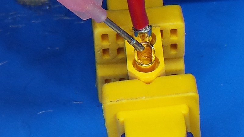
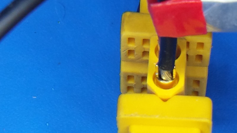
I coated the inside of the terminal cup with a bit more flux:
![]()
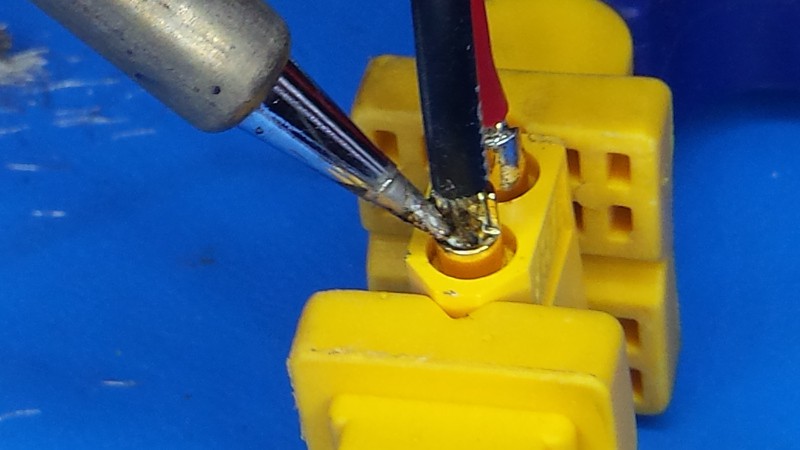
... then I heated it up and added some solder. Note the iron position; I used a clean, well-tinned tip and made sure to heat the metal up enough to melt the solder completely:
![]()
Good adhesion is key! So why did I tin the wire AND the cup? Two reasons: (a) it's tough to have enough hands to add solder to the joint when one is actually inserting the wire, and (b) it prevents oxidation from being an issue in the joint's integrity. I've used flux on both surfaces, so now it's just a matter of remelting the solder and sticking the bits together.
I inserted the wire first:
![]()
Note the clip to hold the wire. I'm holding it with my free hand (the other hand holds the iron), and the wire gets HOT. I don't want to be tempted to drop the wire before the solder has cooled completely; any movement as the alloy drops between the liquidus and the solidus line would result in a cold solder joint.
(sub-tangent: that's why 63/37 solder is nicer than 60/40 when you're dealing with leaded stuff. 63/37 is a bit closer to the alloy's eutectic, meaning the solidus and liquidus lines are closer together and full solidification occurs over a smaller cooling range--less time for movement causing cold joints. See the Pb-Sn phase diagram for more info.)
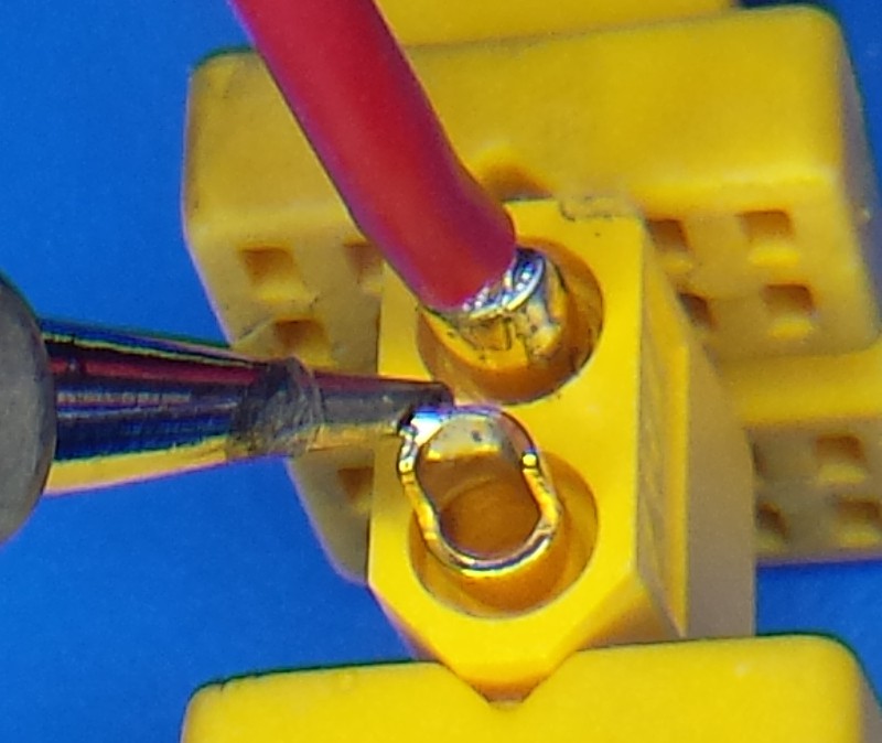
This was the toughest picture to get:
![]()
This shows the final joint after everything has heated up and flowed properly; notice the fillet of solder that runs all around the wire. Not pictured here is prep: after getting everything positioned, I pulled the wire out and remelted the solder on the terminal. Shoving the cold wire in solidified it a bit, but the cup was still preheated to a few hundred degrees. The iron position shown above allowed me to heat the pot up enough to remelt the solder, while also liquifying the solder I'd applied to the wire earlier.
Note: This is the tricky part. If you're using lead-based solder, you'll have a bit more leeway since its melting temperature is lower. With the RoHS stuff, you can't keep the iron on too long or you'll start to melt the plastic housing for the connector (as me how I know!). Keep the iron on long enough to see the solder flow completely into all the gaps, then remove the iron and keep the wire still for at least ten seconds.
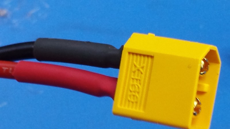
Boom:
![]()
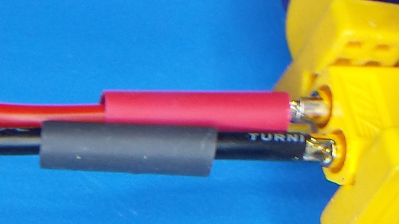
You didn't forget the heat shrink, did you? Well, I did--fortunately I'm building 1-sided cables for now, so I just strung it on from the other side. I'm using 1/4" stuff, but slightly smaller (4mm or so) would be ideal; this stock is a bit too thick to fit into the groove in the plastic, so there's a small ring of metal exposed. Either way, this will do the job nicely:
![]()
So... that's how I'm doing these connectors, but I'm brand new to them. I'd love some words of advice from anyone that has experience with X160-style connectors. How did you reliably solder them without damaging the plastic?
-
Theta actuation and pivot update
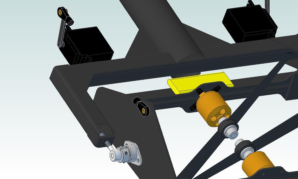
06/17/2014 at 04:00 • 2 commentsQuick update on v07. I modified the rotating thrust frame a bit so it's supported by a pair of rod ends; this is lighter, cheaper, and easier to align than the previous design that just showed a few holes through the CFRP square tube. I also started testing different servo mounting ideas; since I'm not as worried about servo weight or width (although both are important), I swapped out the slim servo from v06 for a standard 20x40 model. The unit I specified is insanely fast and powerful, and I included two in the model; again, I need to do some torque calculations to see if I can get away with a single unit (although they are only 60 grams).
![]()
Notably missing is the threaded rod that connects the two Heim joints. I've constrained them to stay aligned but haven't modeled up a longer rod yet. Also, I've added a split shaft collar on either side (visible between the stainless rod end and the flange mounted bearing here) to secure each shaft laterally. The split design should make this relatively easy to take apart.
On another note, Cubify has started to slow down. I'm using less than 25% of memory and CPU and my graphics card shouldn't be anywhere near maxed out, but I think the program isn't a fan of having so many individual parts and constraints in the assembly. I'm less worried about the slow speed than I am about the fact that it seems to have dropped a few assembly constraints; sometimes when I grab something that should rotate (such as the theta frame), it decides to drop an axle and move around a bit outside its intended range of motion. I might have just forgotten to constrain the model adequately; either way, I'm going to dig back in to doing nested subassemblies to reduce the complexity of the finished assembly. Anyone that's done this with Cubify Design--I'd love some advice. How do you structure your complex assembly trees?
ALSO, PARTS! Yup, more parts are on the way. Rod ends, split shaft collars, shafts, bushings (for the slip ring) and flange bearings should arrive later this week; I'm hoping the Rho brushless gimbal motor arrives around this time too (although it's got a much longer journey). I've also been bugging vendors about the GE power converter, so hopefully I can lock down a lead time for that unit soon. I'm anxious to finalize and construct the mechanical systems so I can move on to instrumentation and control algorithms!
-
Amperage limitations and a small victory
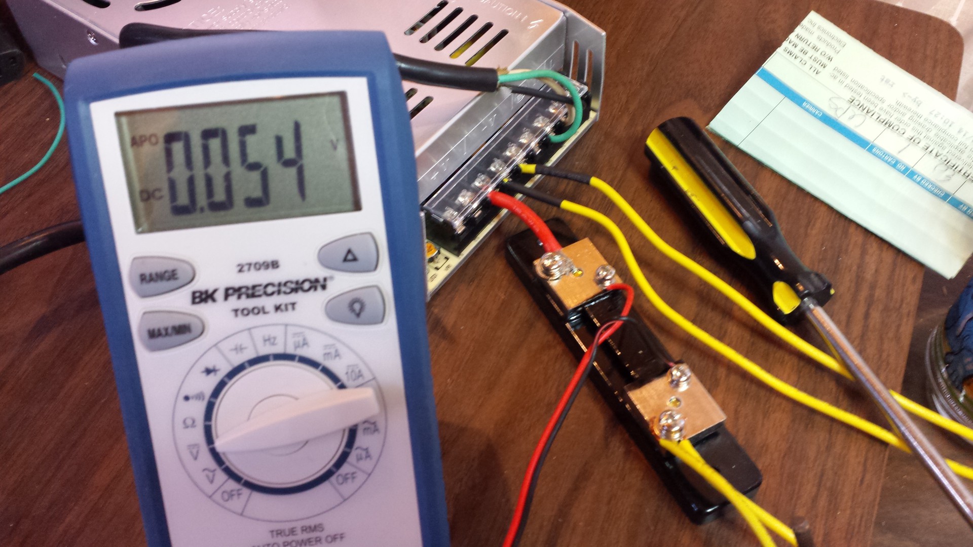
06/13/2014 at 03:28 • 0 commentsI knew there was a chance that my 360W/12VDC power supply wasn't capable of giving the two brushless motors the juice they needed to hit maximum RPM; in order to quantify this, I hooked up a current shunt and ran some full-throttle tests:
![]()
That's a 50 amp full scale 75 mV shunt, so 0.054VDC = 36 amps. Not bad for a supply that should only hit 30 amps, but it meant that I might be current-limited due to my power supply choice. Time to break out the LiPo batteries that arrived earlier today:
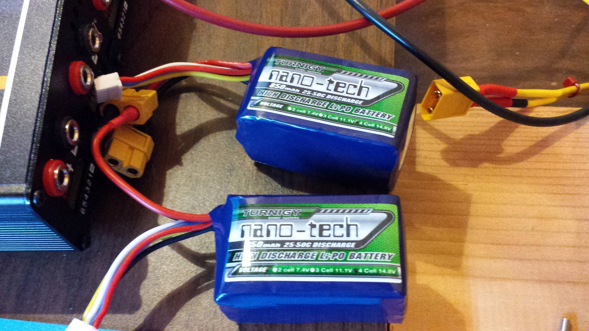
![]()
I grabbed a bag of connectors too, so it was fairly simple to splice 'em in to the existing test rig (one per motor).
![]()
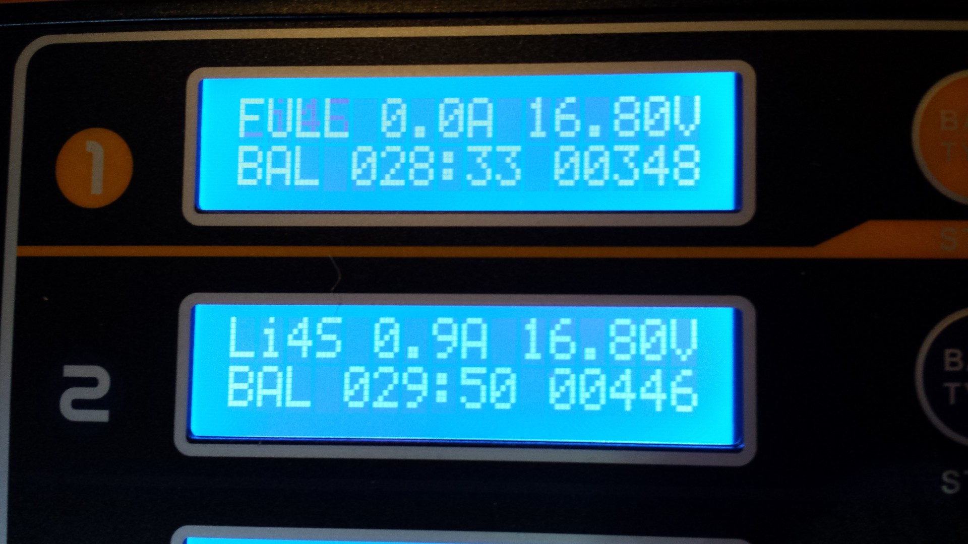
Charged!
![]()
BAMF. 2kg+ thrust, more than enough. Loud and lots more vibration than I saw at 1450g, but the new motor frame design should be quite a bit stronger than the test rig.
Big caveat here: these batteries are 4S units, so they're putting out nearly 15vdc. That means they can turn the motor faster than the 12vdc power supply can, at least theoretically. However, I used the power supply's built-in calibration pot to jack the power supply up to 14vdc and I still got 1450g thrust, so it's hard to say what the limiting factor is. One thing I do know: I need that GE power converter. It'll hit 50 amps at 12 volts and should tell me for sure whether or not my prop/motor combo is adequate.
GimbalBot
Gimbaled thrusters, aerospace-grade adhesives, carbon-fiber-reinforced polymers, and inertial measurement units. This is a space project!
 zakqwy