-
A few changes with v07...
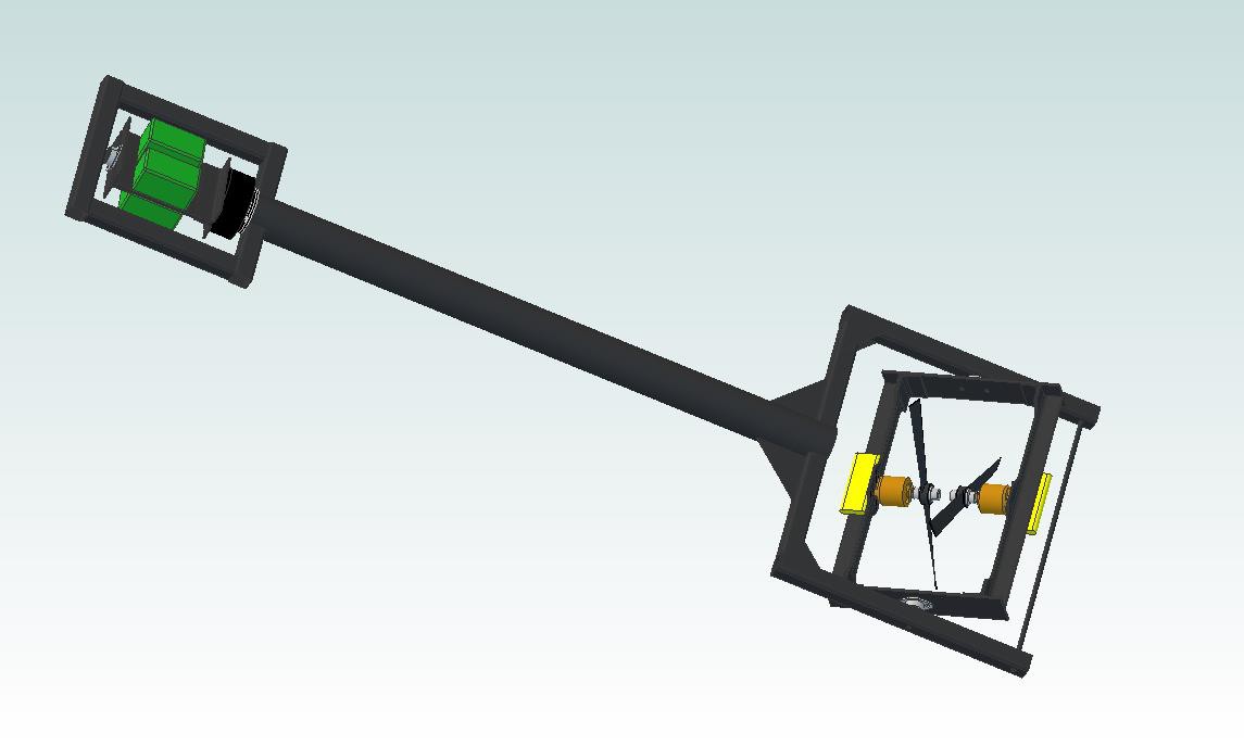
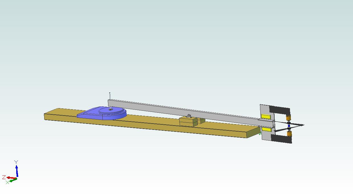
06/12/2014 at 04:56 • 1 commentOkay, so the title is a bit of an understatement. If you've been keeping up with the logs and project comments, you'll know that a few of the ideas that have been discussed conflict with the previous waterjet-cut CFRP design. I decided to explore other construction techniques; CAD models are in the Dropbox repo under /v07:
![]()
Many things to consider here. We'll cover them one at a time.
Thruster Motor Mounts
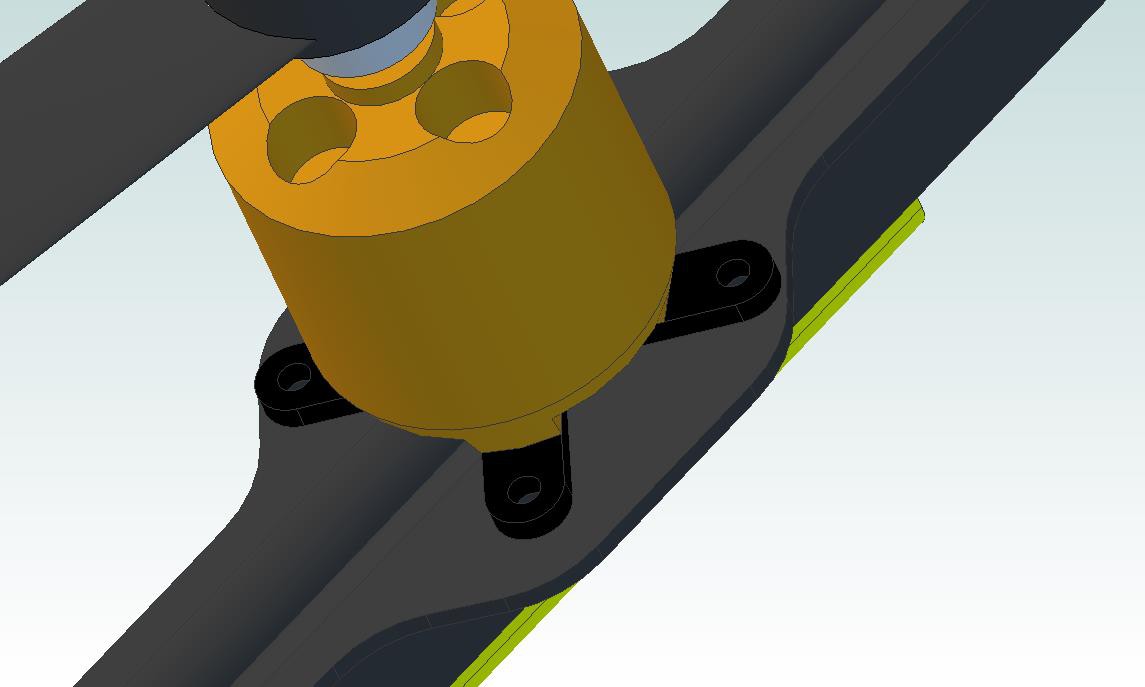
I added the black painted aluminum motor adapters that came with the motors. They're much easier to attach to the CFRP angle stock, and they also have a hole to clear the part of the shaft that sticks out of the back of the motor body:
![]()
(ignore the offset angle bracket cutout, I need to fix that...)
Thruster Motor Brackets
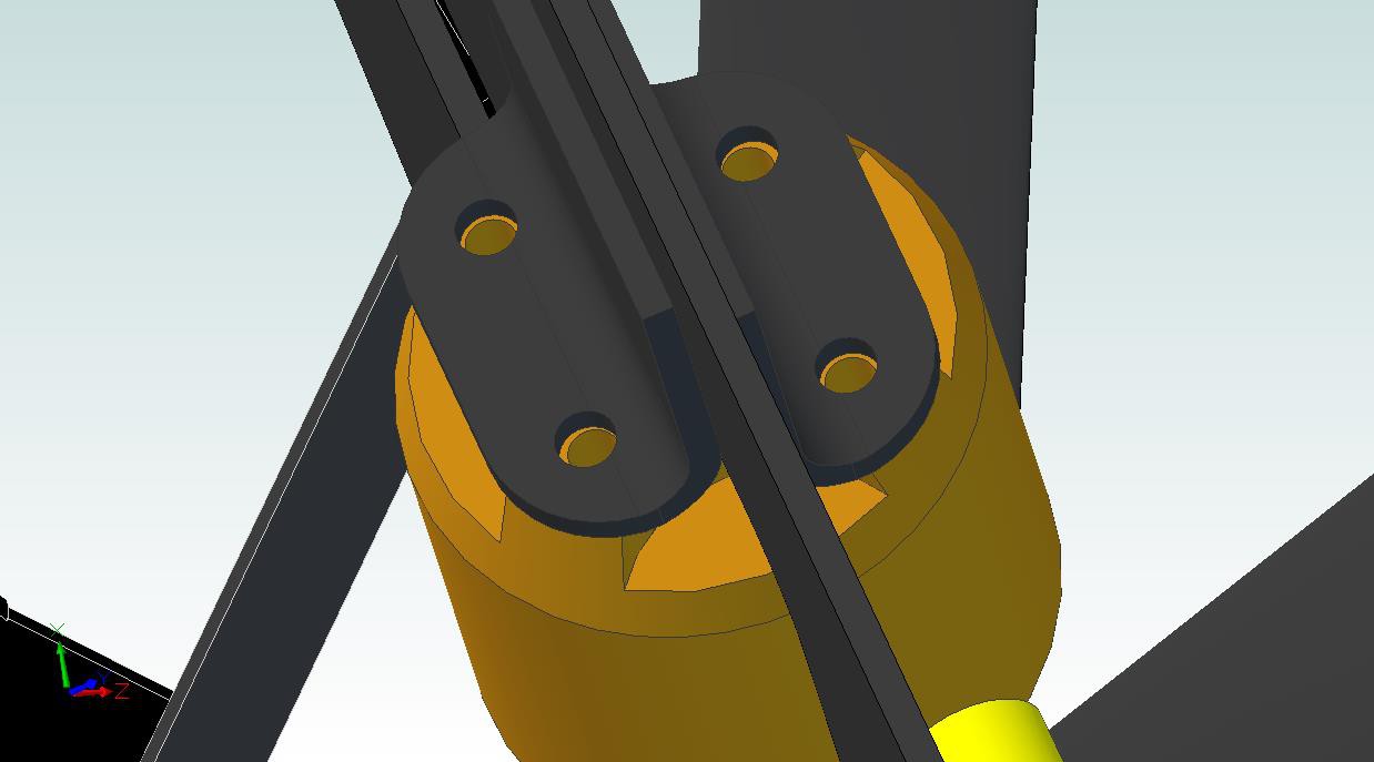
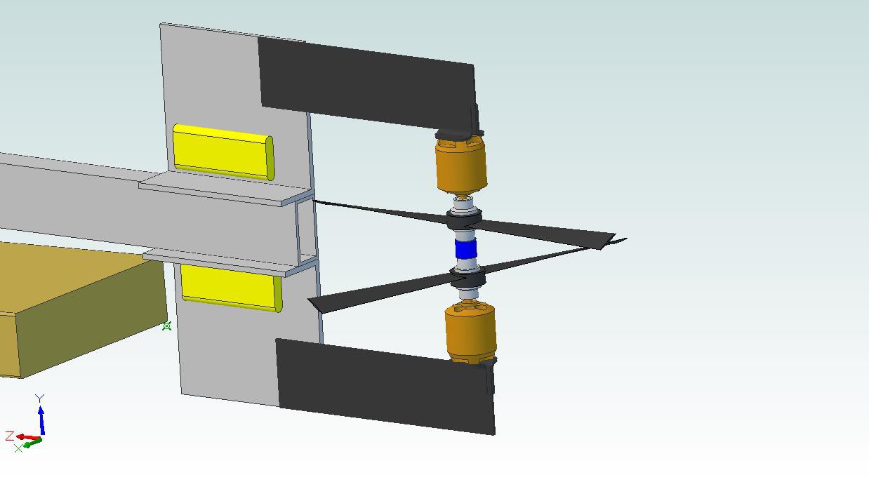
I completely ditched the thruster plate; instead, the motors are supported using a pair of sandwiched brackets that are trimmed back a bit to reduce their cross-section:
![]()
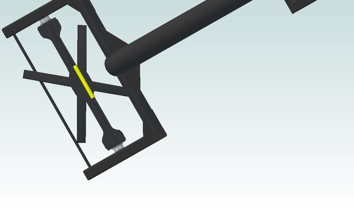
The picture above gives a decent head-on image of the fans, showing the portion 'shadowed' by the motor support. The two motor bracket pairs are then held together by 2.4mm thick CFRP plates:
![]()
It's rigid and doesn't require fancy waterjet work; I can cut the non-critical angle bracket profiles by hand. Space glue is pretty wicked stuff so I'm not worried about the joints pulling apart.
Tube Frame
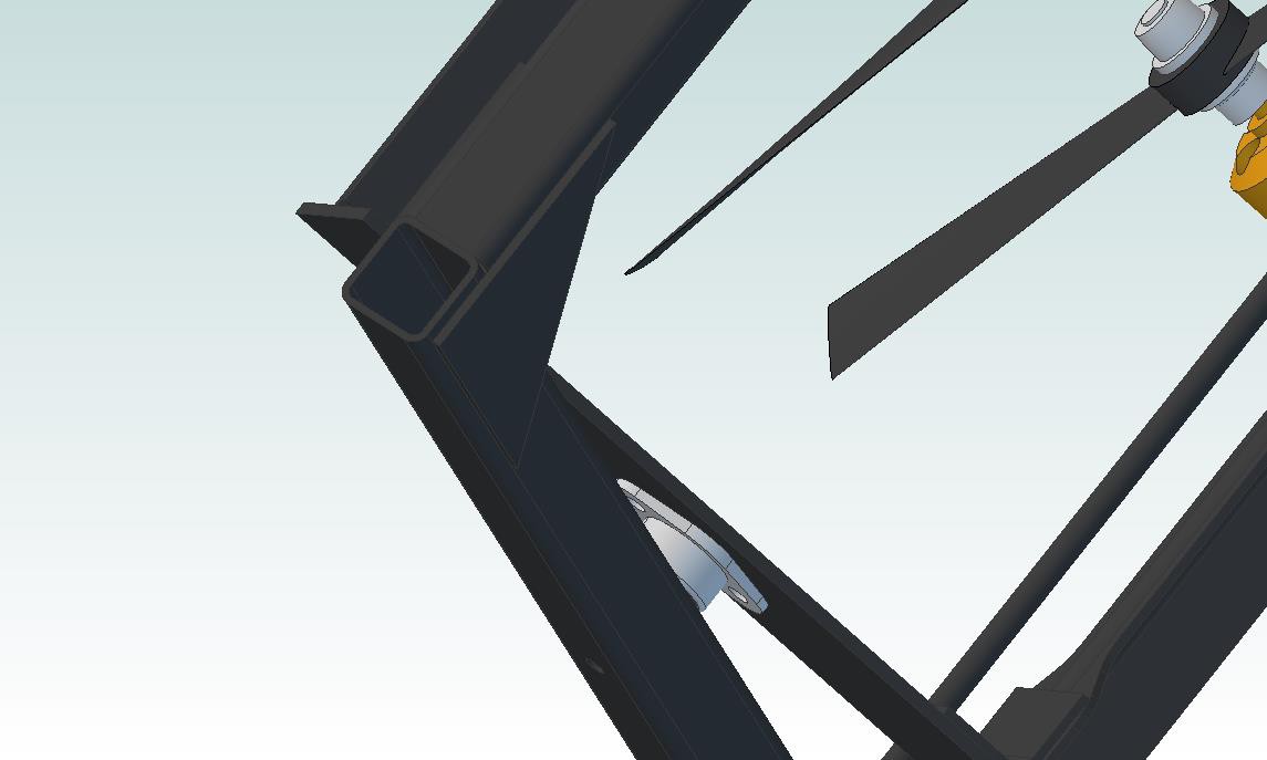
The thruster frame (I need to come up with more consistent names) is supported along the theta rotational axis using CFRP square tubing stock:
![]()
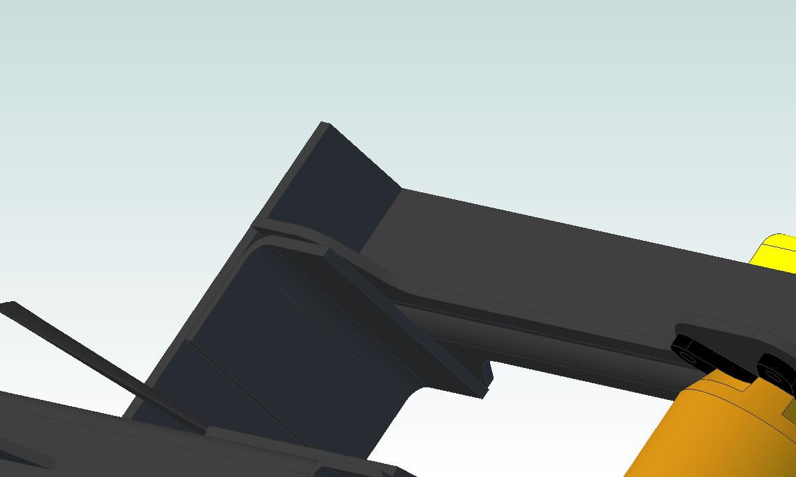
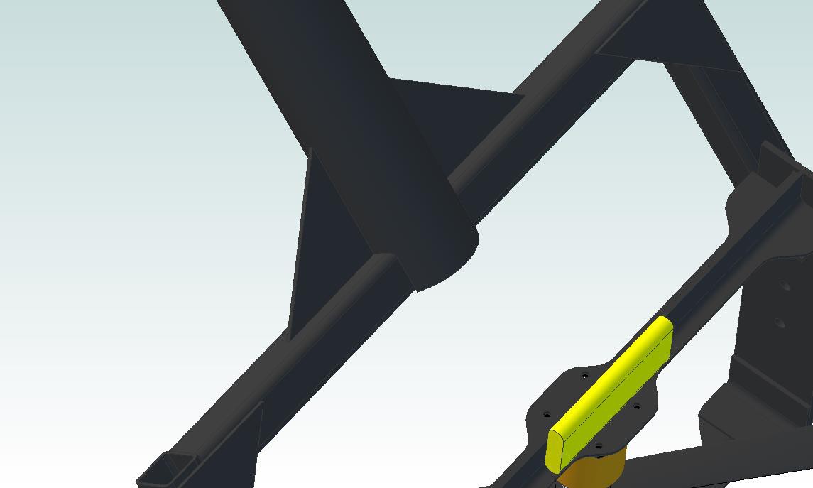
Hooray, gussets! These square tubes then connect to a central tube that forms GimbalBot's longitudinal frame:
![]()
Reaction Wheel
Sharp eyes may have noticed the lack of power converter and slip ring on the now-missing thrust plate. Unlike the theta servo (which just hasn't been drawn up yet), these items were intentionally left off the thruster plate. They're moving up!
![]()
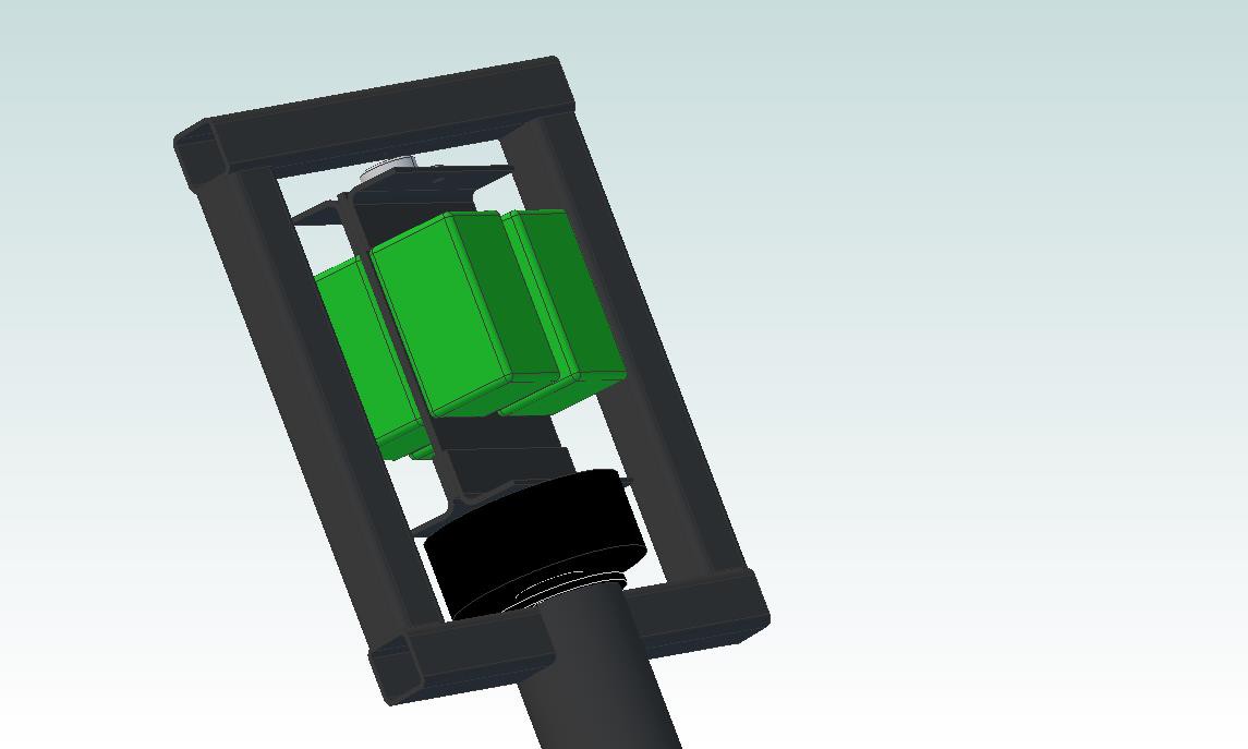
If you're not familiar with reaction wheels, it's worth taking a look through the Wikipedia article. They're essentially masses that can be rotated relative to the main body of a craft to affect its orientation using conservation of angular momentum. By spinning the batteries one direction, I can cause the rest of the craft to rotate in the opposite direction in an extremely controlled fashion.
A few details on the picture above:
- The green boxes are the four 4S (14ish volt) LiPo batteries. I'll be wiring 'em in series, as discussed in a previous project log.
- The black hockey puck looking dealie is a brushless gimbal motor. These units are typically used to stabilize UAV cameras; this particular unit is designed for a 600-1200g camera, which is perfect for my batteries (they actually total 400 grams, so I might be going a bit overboard on the motor). Best part: it's got a hollow shaft, so it's a great match for a slip ring!
- You can't really see the slip ring; it's the black disk below the black motor, and most of its body is in the CFRP body tube. I'm still working out mounting details, so dimensions and such might change a bit. If you pull apart the model, you'll notice that the slip ring goes through the square tubing cross bar; yup, it's not quite finished yet.
Other stuff
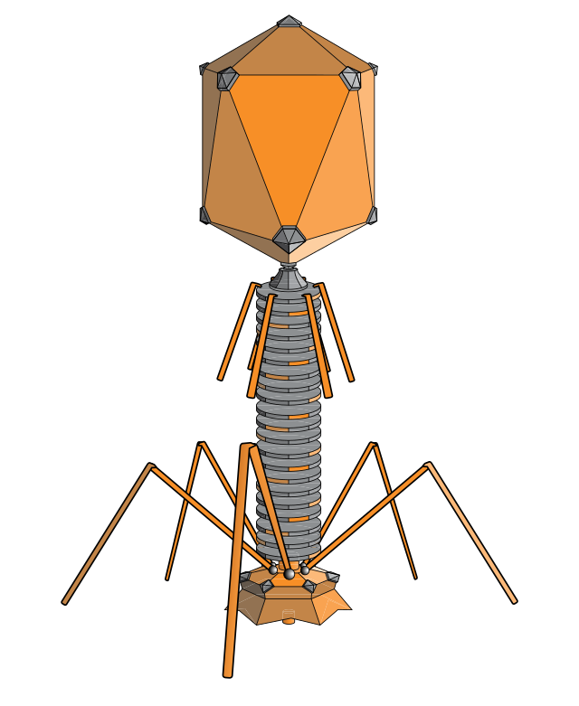
The Cortex M4 board, IMU board, and power converter aren't in the design yet. I'm probably going to put a control board plate below the slip ring and rho motor that will hold these parts. Additionally, I haven't added landing gear; I'm thinking about building something out of pulltruded 5mm CFRP tubing, since it's strong and light. This design is pushing me to consider changing the project's name to GimbalPhage:
![]()
In any case, I'm currently a tad over 1330g with the design shown above. Add in the converter, IMU, control board, theta servo/linkage, wire, and landing gear, and I'm probably pushing 1600g. Definitely need to get the thrust over 2kg if I want satisfactory performance.
Parts currently en route
- Slip ring (just arrived!)
- Batteries
- 4-gang battery charger
- Brushless gimbal motor
- Silicone-insulated 14-gauge wire
- Various battery plugs and adapters
- A bunch of different propellers (8 and 9 inch)
- Other random bits and pieces
Next steps
- Break out the Physics 121 textbook, re-learn how to draw free body diagrams, and try to figure out a few numbers (torque and actuation speed requirements, etc). I'll definitely need a hand on this one, my Newtonian mechanics is a bit rusty to say the least.
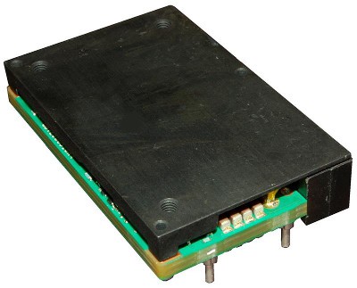
- Keep bugging the GE guy to sell me a damn power converter.
- Improve the thrust test results.
- Check full-RPM current values on the existing power supply; I think I'm probably maxing it out, so I might have some headroom left with the existing motor/prop combo.
- Test the new props as they arrive. The 9" units will require minor modifications to the thrust rig, but nothing too serious.
Thoughts? Questions? Comments?
-zach
-
Initial thrust testing results are in!
06/08/2014 at 16:52 • 2 commentsCompleted the first thrust tests earlier this morning. GIMBALBOT IS GOING TO FLY!
![]()
![]()
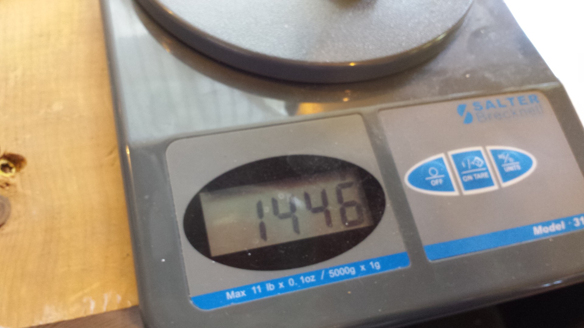
I'd love a few hundred more grams of thrust, but 1446g is a great start!
-
Building the thrust testing rig, part 3
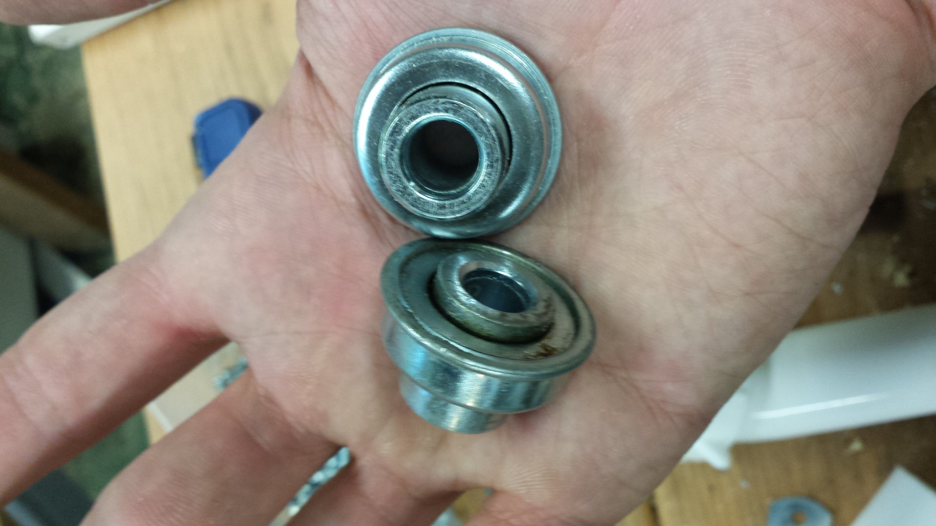
06/06/2014 at 23:58 • 0 commentsFor some reason, I didn't order the cheap pillow block I listed in the GimbalBot Expense spreadsheet. It was only $10, but I just... didn't do it. In any case, I was at a local surplus store picking up parts for another project earlier this week and grabbed a pair of flanged ball bearings:
![]()
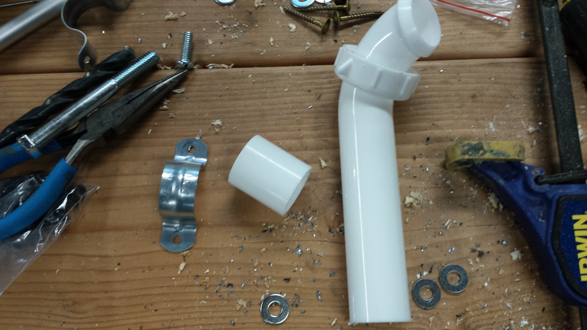
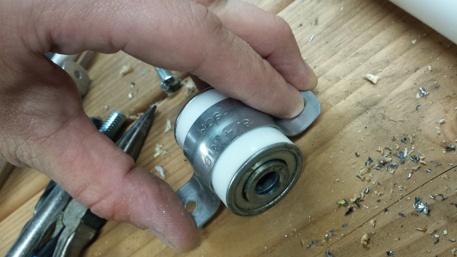
Hmmm.. that's not a pillow block. Fortunately, I had a spare PVC trap lying around whose ID matched the bearings. I introduced the trap to my chop saw:
![]()
... and paired the pipe stub up with a 3/4" steel pipe hanger:
![]()
BAM, DIY pillow block. Probably came out about even if you count the cost of the trap. I stand behind my tendency to occasionally reinvent the wheel--helps clean out the junk bins.
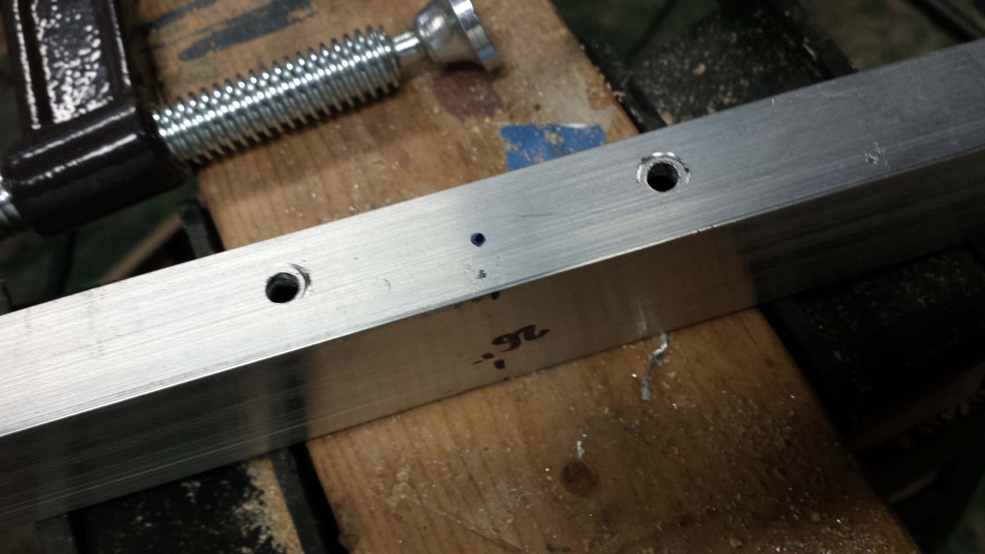
After that, it was a simple matter of measuring the halfway point between the center of the props and the end of the thrust rig arm and drilling a few holes:
![]()
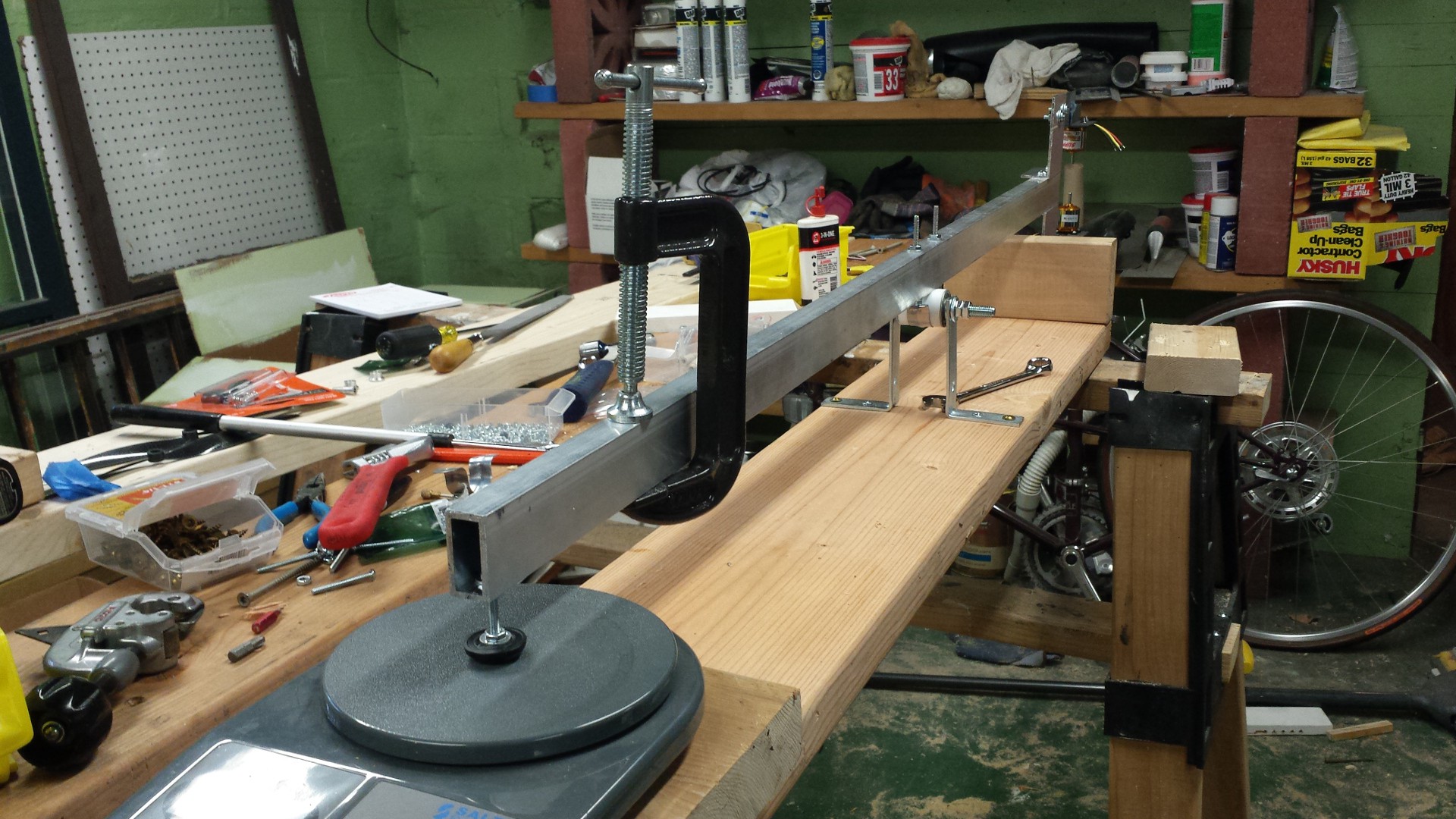
Bolt everything together and the mechanical portion of the test rig is done:
![]()
Probably should have hung a backdrop for that picture. Project house basements tend to look like that, I'm afraid.
A few details:
- The C-clamp is an easy way to adjust the preload on the scale. I don't really care what the value is, I just need it to be stable and high enough to offset the weight of the motors. After preloading, taring the scale is easy.
- The little rubber foot on the arm worked better than expected. Not sure it's needed, but it'll keep everything from slipping about.
- The bearing assembly is held up with two slightly modified angle irons that are screwed to the 2x8 base. The bearings themselves aren't terribly high quality (I think they might have been heavy-duty filing cabinet wheels at some point), so they have a decent amount of slop; however, the joint seems to have fairly low friction so I'm confident that it will work.
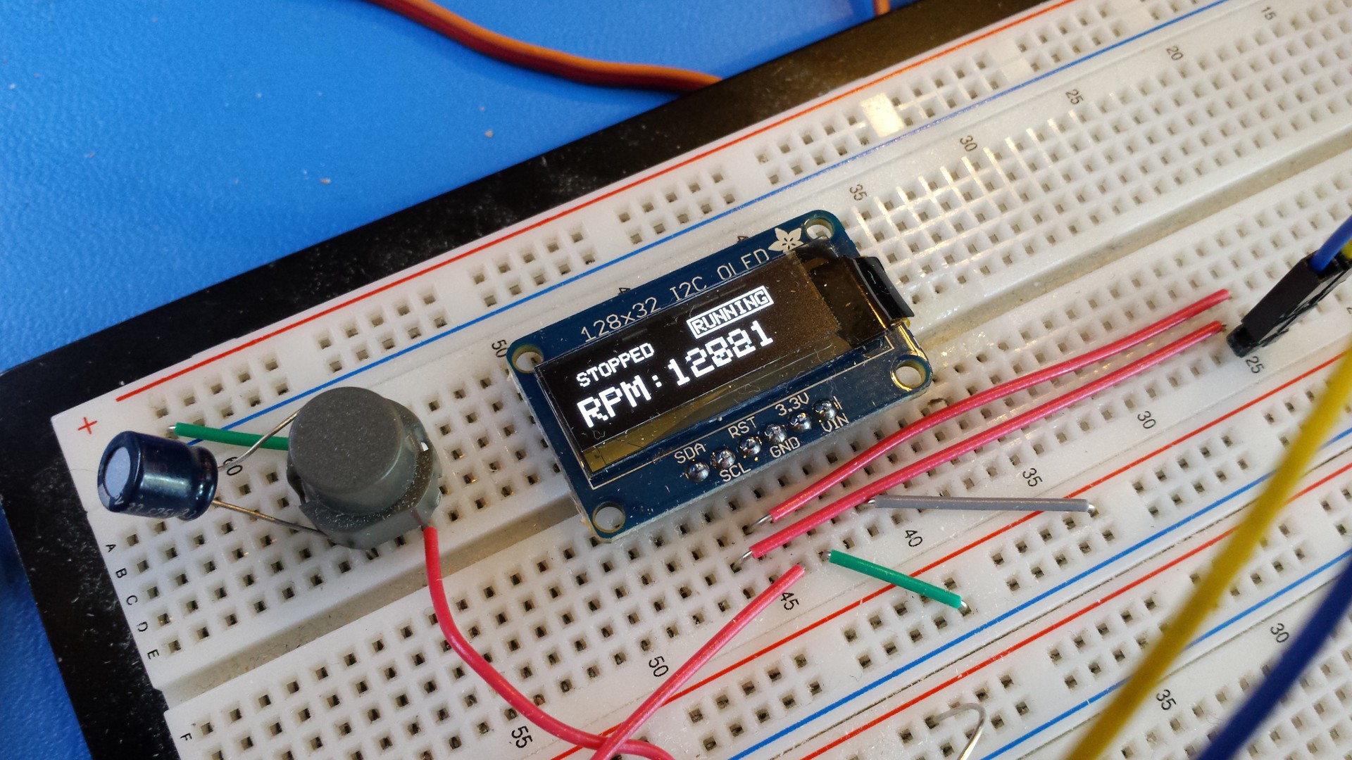
Next steps: wire up the speed controllers, throw together a servo pulse generating circuit, hook up a high-current power supply, and watch the CFRP fly.
-
Shower Concerns
06/03/2014 at 00:46 • 2 comments"Shower Concerns" -- so called because they often come to you whilst in the shower. I had a few come to me today:
- Propeller nuts. I've got opposite-pitch propellers that are mounted 180 degrees off from each other, so the motors will be rotating in opposite directions. The nuts are both the standard right-hand type, and I've also taken the liberty of chopping off the part with the little hole (which I assume is for a safety cable). They're technically a kind of collet, so this may not be a concern; but I'm a bit nervous about one of the nuts spinning off during operation. If this happens, my current plan is to hit it with some Loctite Blue.
- Rho control. Newton's second law: every action has an equal and opposite reaction. In this case, assuming the rotating gimbal and the main frame weigh the same amount (and gyroscopic/aerodynamic effects are negligible, which they surely aren't), rho actuation would actually cause the frame to rotate in the opposite direction compared to the gimbal. That means if the angular change between the two subassemblies is x, the actual rotation compared to a reference plane in space would be x/2. Three ways I'm considering handling this issue:
- Bottom-up redesign of GimbalBot, probably ending up with a more traditional gimbal design that uses two 'hinged' axes. That would also do away with the expense and complication of the slip ring and power inverter.
- Develop a rho coefficient table that increases delta-rho values beyond their initially calculated values to 'overshoot'; this would continuously rotate the GimbalBot frame, but would point the thruster in the right direction.
- Correct for the frame rotation by modulating the relative propeller speed. This would essentially add a layer to the motor speed control loop, taking another input from the IMU system.
I've realized that the main reason I'm hesitant to redesign the 'bot is because I've spent so much time on the current iteration. However, moving towards an X/Y gimbal from the current polar design would save me lots of money and headache: no more power inverter ($250 + 74 grams), no more slip ring ($200ish + 50ish grams), and better battery/motor options (no longer constrained to a 50-60vdc supply and a 1100-1300kv motor).
Thoughts? Should v07 be a clean sheet design, given that I haven't pulled the trigger on any of the aforementioned pricey components? Either way, I'm still going to do thrust tests using the setup I've (mostly) built.
-
Building the thrust testing rig, part 2
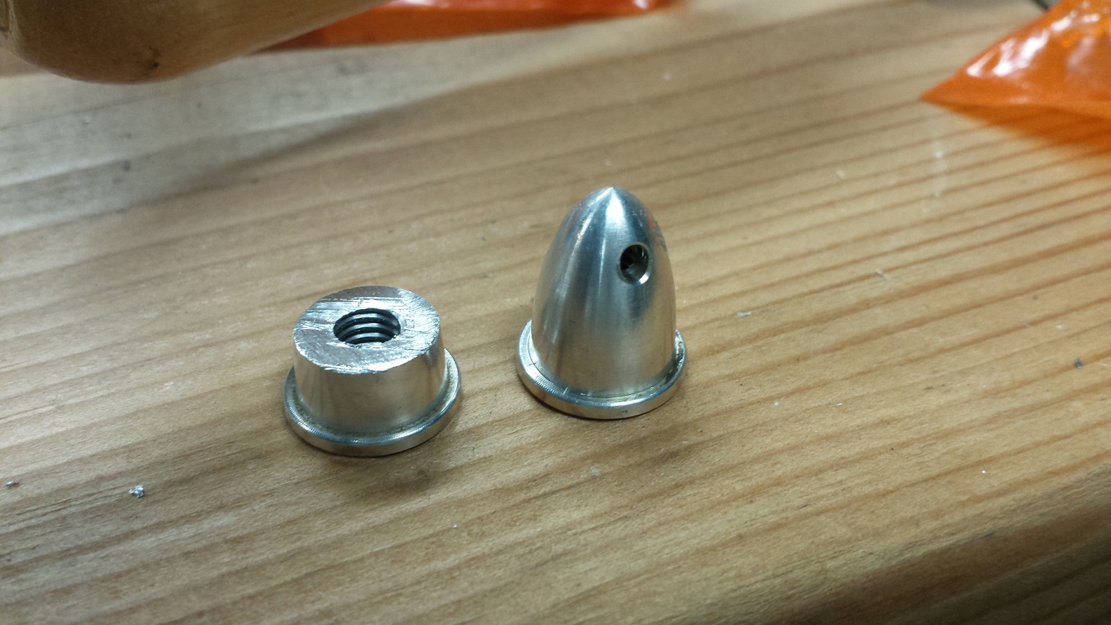
06/02/2014 at 00:16 • 0 commentsI did a bit of assembly work today on the thrust testing rig. First thing's first: I needed to cut down the prop nuts (there must be another term for these) since I need the motors as close together as possible:
![]()
I filed the cut edge down a bit, but I suppose I might need to hit it again if the balance is upset too much.
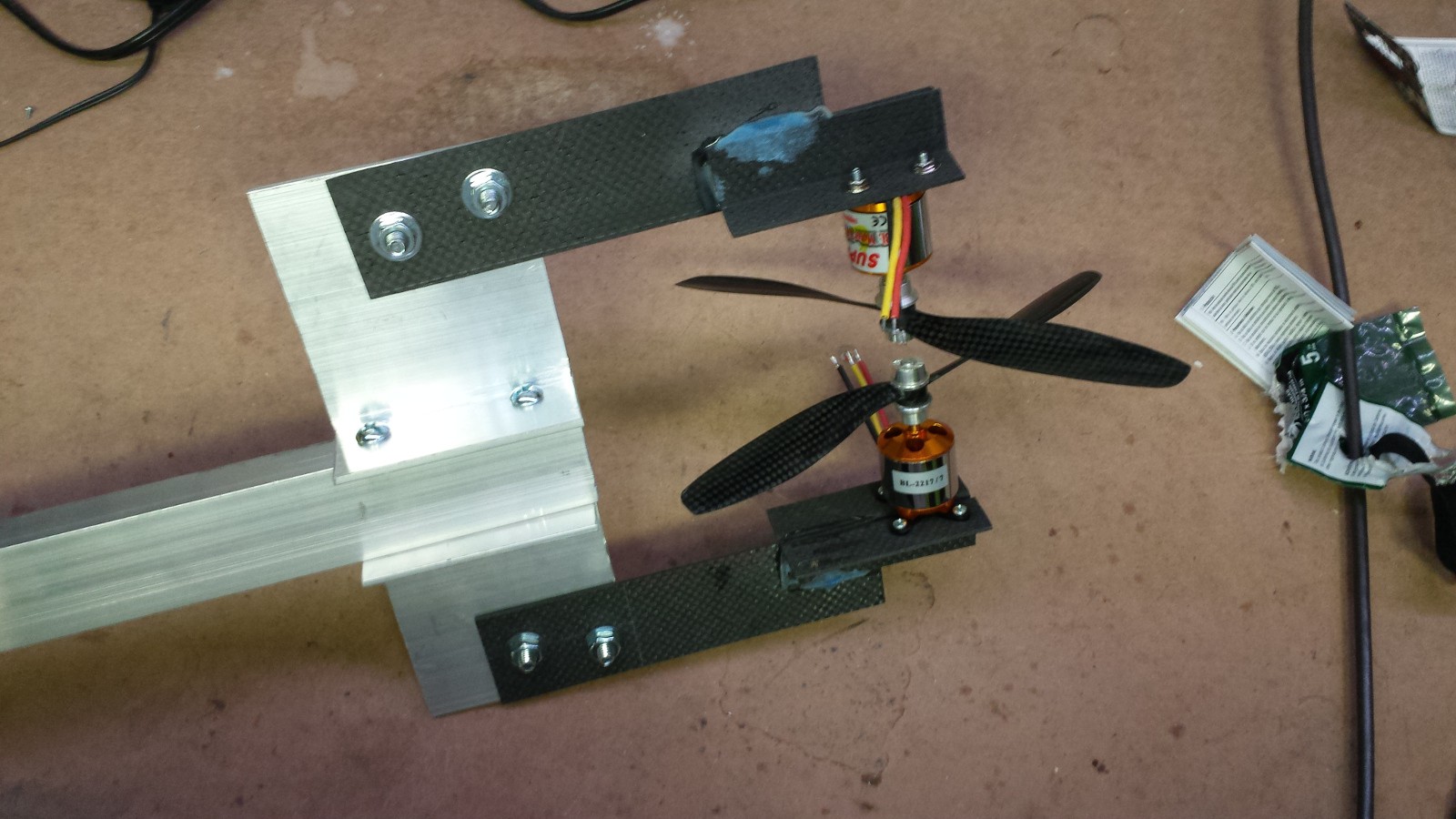
Other than copious amounts of painter's tape sticking to the CFRP angle stock, the space glue seems to have done its job. I drilled a few holes (see previous post regarding PPE), re-drilled a few holes, slotted a few misaligned holes with my Dremel, and eventually cobbled together the 'business end' of the thrust testing rig:
![]()
It's like a weird 4-foot-long trident dealie with crazy propellers on the end. Or the eye of Sauron, if you replace the fiery center with rapidly spinning blades of death. Either way, definitely one of the odder contraptions that's come out of my basement.
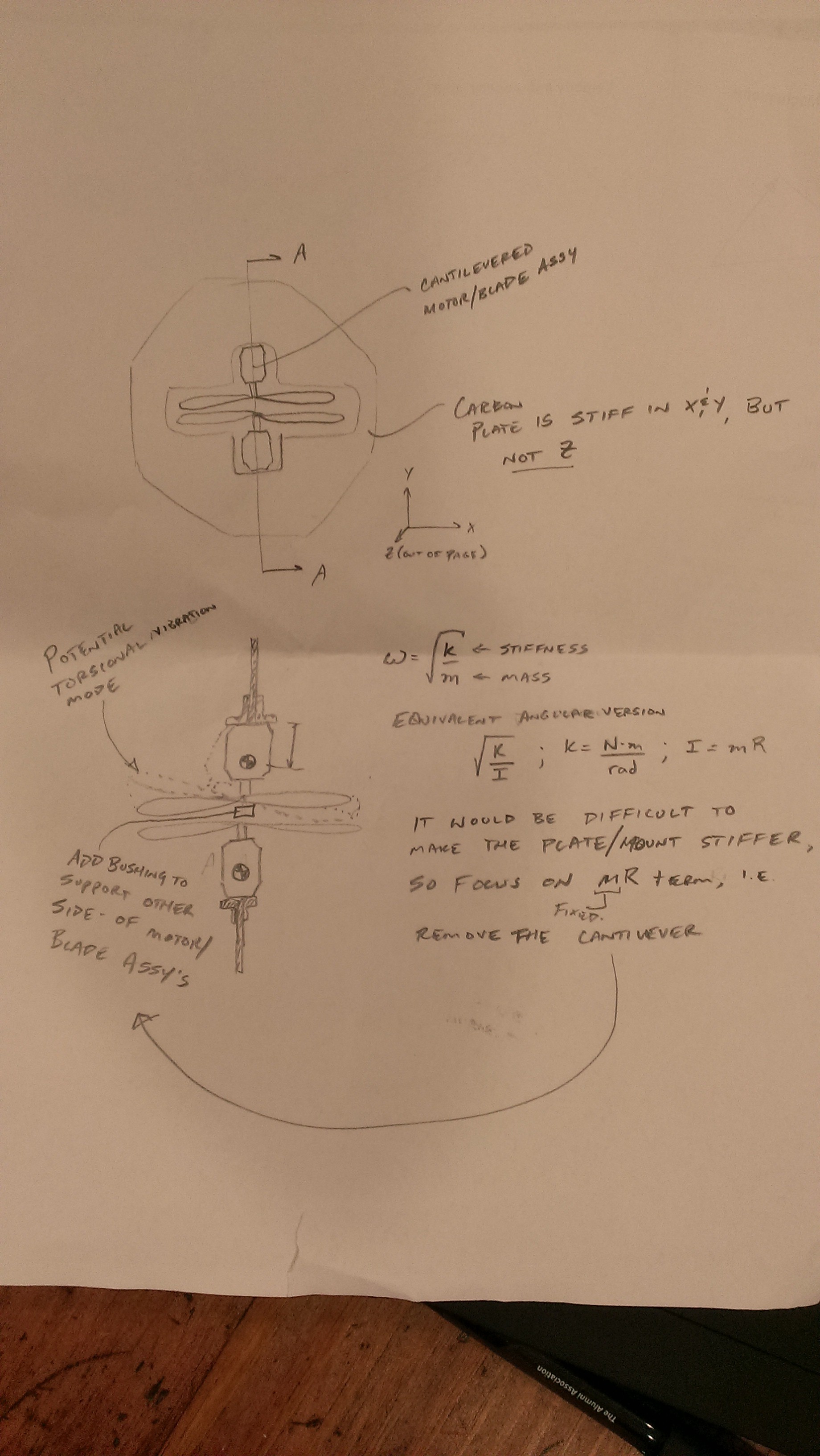
No testing yet, but that will come soon. I have a 30amp/12vdc power supply that will conveniently not power both motors, but I'll be able to at least get them spinning. First observation: as Jefito reminded us in late May, the plates lack lateral stiffness. It's quite easy to push the propellers sideways, so I'm curious to see what happens at 15k rpm. I thought about gluing on some reinforcing strips to stiffen up the CFRP plates, but I'm inclined to run the rig up to a few thousand revolutions first to see how badly it vibrates. So what will fail first: the glue joint or the plate itself? Or will the bolts just back themselves out and fly apart? Stay tuned..
-
Building the thrust testing rig, part 1
05/31/2014 at 23:20 • 2 commentsA few boxes arrived this week, so I got started on the thrust measurement frame this weekend. I watched a number of videos on safe CFRP working procedures (since I'm cutting simple shapes myself at home), including the one in the previous post. I spent the last few hours with nitrile gloves, safety goggles (not glasses), a P100-rated dust mask, and a HEPA-filter equipped vacuum directed at my work. If you work with this stuff, I highly suggest you do the same, and clean everything up before you shed your PPE.
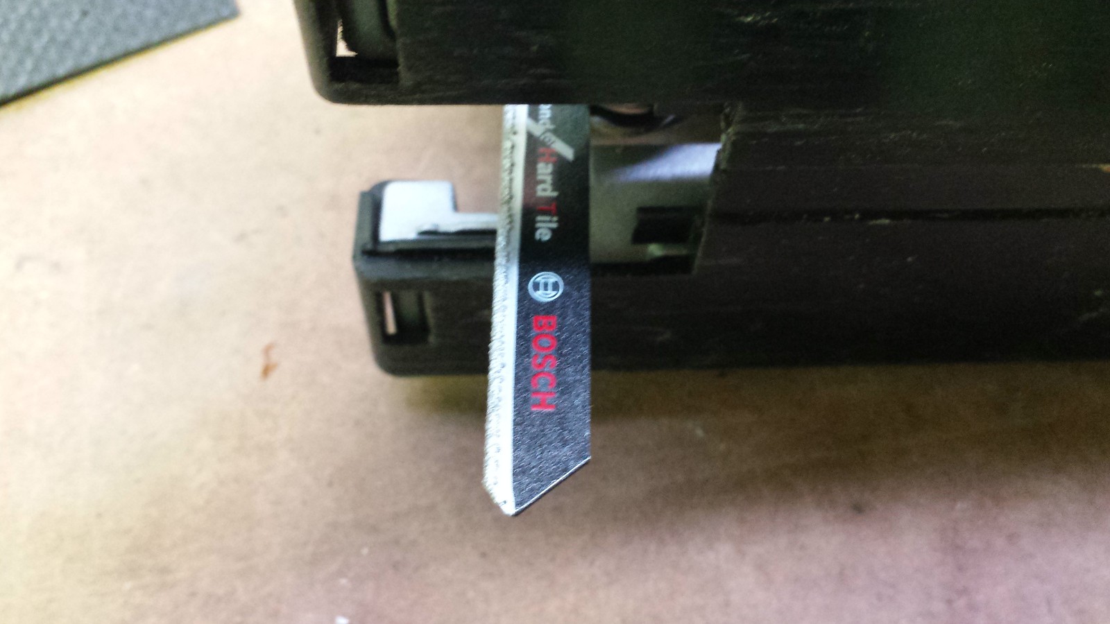
First step was getting a few cutting tools. For the 6" plate cuts, I used a diamond-tipped jigsaw blade:
![]()
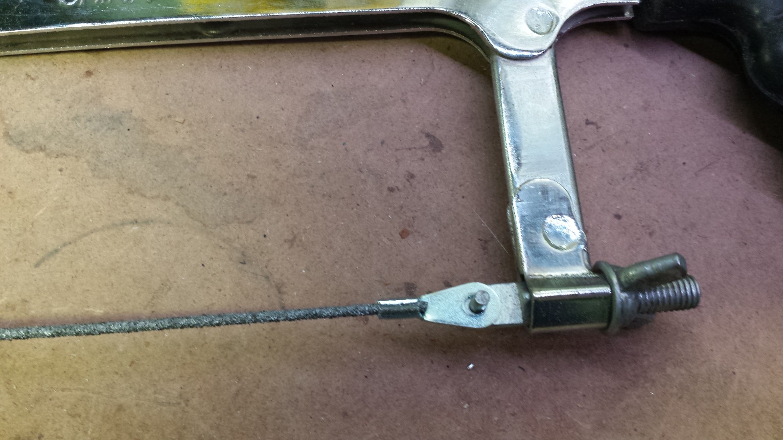
I cut the 3/4"x3/4"x1/16" angle stock using a carbide hacksaw blade:
![]()
![]()
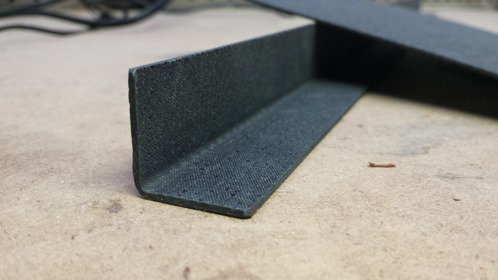
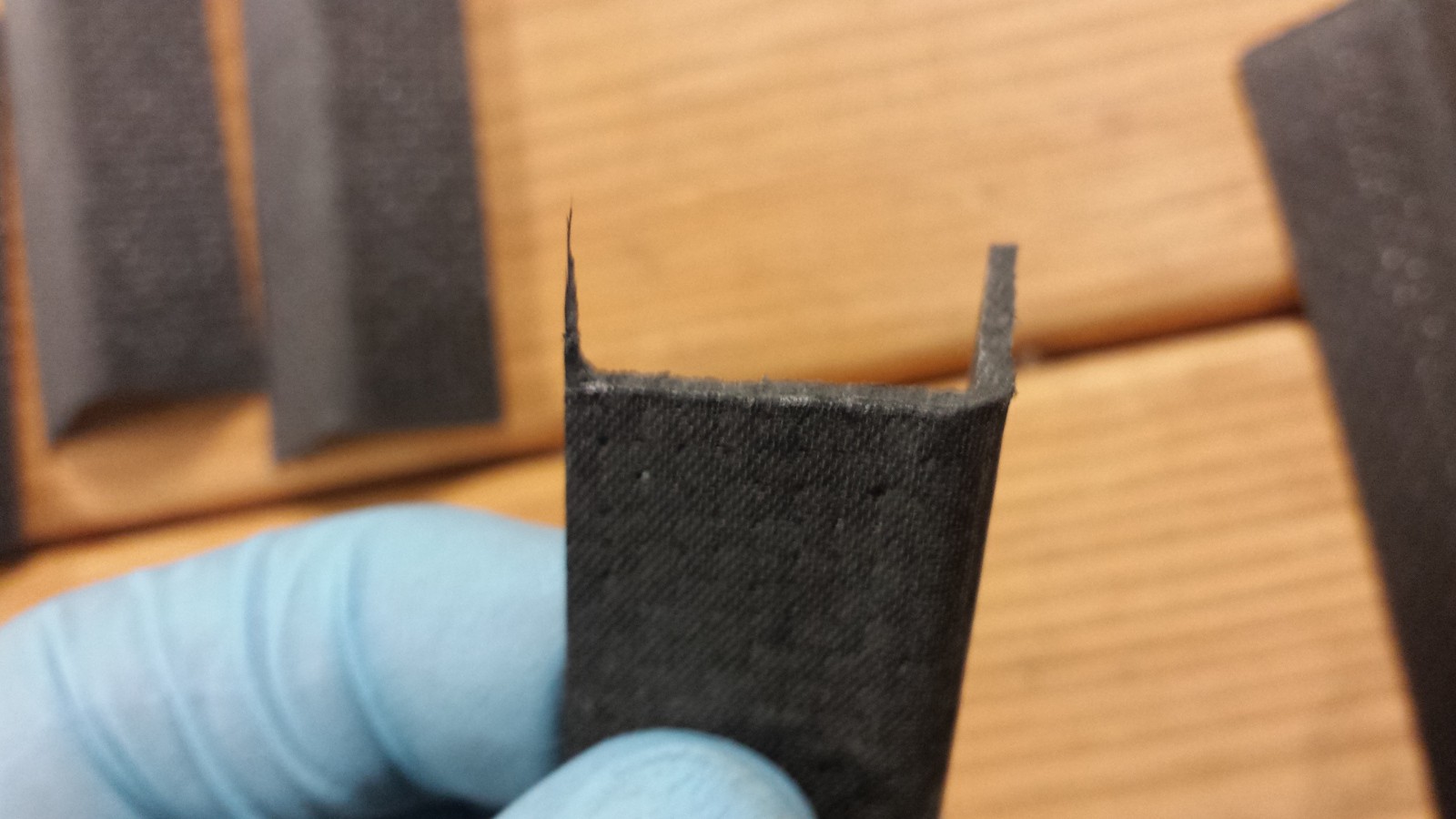
Both tools worked decently well (and were fast); the hacksaw blade tends to pull off a splinter at the end of the cut, which could probably be fixed by starting from the other side (but I just sanded it off):
![]()
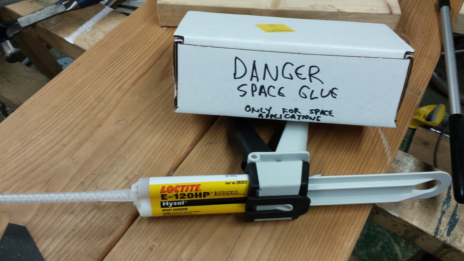
While I previously tested my Space Glue by adhering a few random screws together (they held really well), I didn't want to waste a mixing nozzle on scrap; just eyeballed the ratio like I usually do with epoxy. Now that I'm gluing real stuff, I got the whole setup going, fancy mixing nozzle and all. Super handy:
![]()
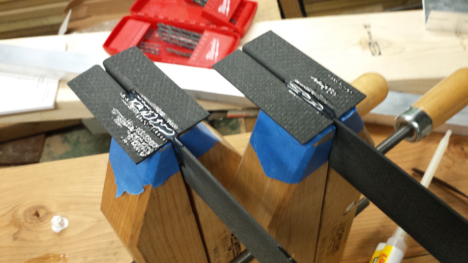
Since I'm constrained by the 6" CFRP plate (I actually have some longer stock that's a different weave, but I wanted to use the same stuff I'm building into the design), I ended up extending the angle stock a bit so that the plate would overlap the aluminum bracket a bit more. I'll likely take a slight thrust hit since I'm 'shadowing' more of the propeller cross section, but that doesn't concern me for testing:
![]()
Sorry about the blurry pictures, I was trying to operate a touchscreen phone with my gloves on (and yes, the screen is now covered in carbon smudges and space glue). More to come tomorrow, this stuff wants 3 hours to set so I'll probably let it go overnight before mounting up the motors.
-
Found some good CFRP cutting/finishing info
05/28/2014 at 03:13 • 0 commentsNot much of a post, as I'm waiting for a few items to arrive for the test stand; in the meantime, I'm not planning on getting the test stand parts waterjet cut, so I've been researching safe operating procedures for cutting plate and tube by hand. This video popped up; hoping to see a bit more info on dust removal, but it seems like a good starting point (no affiliation):
-
Electrical Considerations, Calculations, and Constraints
05/24/2014 at 16:35 • 0 commentsAs I wait for parts to build the propeller thrust testing jig, I want to dive into one of the primary design constraints that has driven many of the decisions illustrated in the various CAD models. Way back in early May, I showed a revised frame design that included a slip ring; the intention behind this device is to allow Rho to rotate freely though 360 degrees without having to back up and unwind the thruster motor power leads. As discussed in greater depth in that post, I'm not concerned about individual thrust vector changes; realistically, dRho and dTheta shouldn't be too high for a given control change. However, I don't want to worry about Rho hitting the limit of its range of motion after a sequence of unidirectional corrections, as the 'unwinding' procedure wouldn't be instantaneous and would result in the fan gimbal crossing unwanted thrust vectors.
While I've been piecing together the CAD model from other various constraints (the Theta servo and standard CFRP plate dimensions, for example) I've also been shopping around a bit for off-the-shelf slip ring options. More discussions with Curtis suggest that Moog makes a wide selection of decent units, so I started rooting through their catalog to see what is available. Generally, I wanted something as light as possible, with minimal cross-sectional area, that would handle the current and voltage needs of the thruster assembly. Additional bonus features would include (a) low connection noise so I could send control signals through the ring (rather than a short-range RF link); (b) low static and dynamic friction; (c) long-life; and (d) [this one is a stretch] some axial- and radial- load handling capability.
So what's out there? Lots. Mercury wetted stuff seems like it has some good features: low noise, low friction, great capacity for a given size--but they have more stringent mounting orientation requirements, probably to keep the Hg in the right spot. The bigger issue in general, however, seems to be in current and voltage ratings: as a rule, it seems like these devices are rated for lower currents than I need at my voltage range. Bumping the current capacity up sufficiently makes the device hilariously large, as I end up with something rated in the low kilowatts.
Time to run some numbers, working backwards from the thrust calculation site I found some weeks ago.
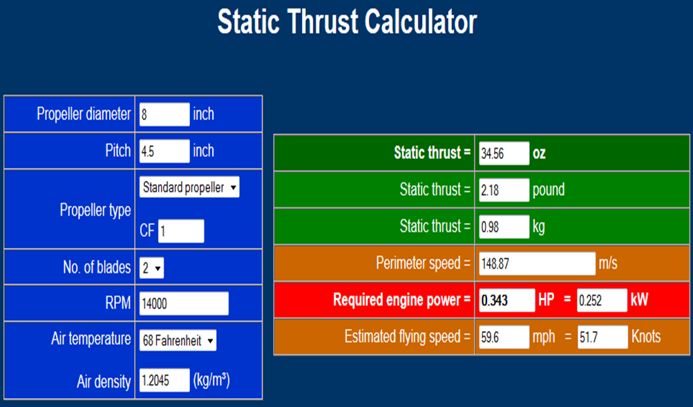
Based on the 12x12" CFRP sheet constraint (and the need for a fair amount of width on the pitch ring), I figured that the largest diameter prop I could fit is 8". Targeting ~1kg thrust per propeller, the calculator suggested I would need to spin around 14k RPM, which (assuming a lot of things about the propeller, not to mention ambient air density and so forth) would require ~250 watts of motor power:
![]()
Getting back to real-world thrust testing, I'm concerned about how two contra-rotating propellers will 'stack' in terms of thrust (some literature I briefly studied suggested 20-30% loss, and net value would likely depends on more variables than I could realistically model); either way, I wanted a decent amount of overhead, so I decided to (a) size the motors for higher wattage (and RPM) capacity, and keep the overall system weight minimal even if on paper it looks like my thrust:weight ratio is decent.
So... call it 600 watts for a pair of motors. Most brushless stuff I'm looking at is sized for the RC world, meaning 2-4 series-connected LiPo batteries. Think voltage in the range of 10-20 VDC, give or take. That means 30-60 amps at peak power demand. Not a lot of slip rings available that are optimized for that specific voltage and current range: as I alluded to above, a 60 amp slip ring might be rated for 250 volts, and they tend to be quite large.
Another great suggestion from Curtis: voltage conversion. What if I sent a higher voltage at a lower amperage through the slip ring, then stepped it down for the motors? I mulled this over a bit and realized that I could string together a bunch of small LiPo batteries (so I wouldn't need to step-up too), dump high voltage/low current through the slip ring, then connect that to a voltage converter small enough to fit on the motor plate. I didn't think that would happen, but a deep dive into various catalogs produced an ideal unit from GE's Critical Power division. The device is rated for 52-60 VDC in/12 VDC out at 600 W, and it's the size of two motor controllers! The unit does have cooling airflow requirements, but I'm not too concerned about that--after all, it'll be mounted right above two propellers:
![]()
Once I found that GE device (it's the mysterious black box mounted to the motor plate you might have noticed if you've opened up a recent CAD model assembly), I was able to select a reasonable slip ring; the unit I'm using has tons of circuit pairs, but I'll parallel most of 'em together to handle the motor load. I'll also probably send lower voltage to power the ESCs and servos, and probably to try control signals too--hopefully that works and I can dispense with the wireless link. K.I.S.S., right?
12vdc out of the GE unit drove the decision to spec a pair of 1250kv motors: at 12v, I'd hit 15000RPM, and the corresponding current is right at the limit of the power converter. On paper, it seems like everything adds up; I've said it before a few times, but the project really does come down to thrust testing at this point.
That's where we stand. My challenge now is getting my hands on the hardware; I reached out to GE in several ways and eventually got a call from a local rep, who is working to get me two units. These devices are only sold in case quantities through my normal distribution channels, and I don't want to buy 24 of 'em just to use one. Likewise with Moog: no response on pricing yet, so hopefully I hear back soon.
Anyone have any thoughts on a better way to do this? I'd love to avoid using a converter altogether, but 60vdc brushless motors (that hit my size and power requirements) seem to be tough to find, since there aren't many quads that use 16S LiPo configurations. I don't think building my own converter makes sense, since that's a pretty intense engineering effort by itself and the GE device appears to have excellent power density.
-
Time do (finally) do some thrust testing
05/22/2014 at 03:43 • 1 commentOkay, time to get serious about figuring out if GimbalBot will ever fly. That means doing some static thrust tests on the propeller; and not just one, but two, in a coaxial contra-rotating configuration. Oh yeah, and with the propeller nuts facing each other, like they will in the final model.
I had originally intended to use the 4' chunk of rectangular aluminum tube I picked up last week to build a simple balance. I hadn't really figured out details on the actual motor connection, since I wasn't entirely sure how I was going to mount the motors. I've since decided (as of v05 or so) to use brackets cut from commercially available CFRP angle stock, as shown in the close-up picture below:
![]()
(note that the brackets are slightly offset, as the motor's bolt pattern is a 'helpful' trapezoid. Also, the holes aren't perfectly aligned due to my subpar CAD modeling skillz.)
So... now that I have this designed, why not use that as a method to constrain the motors during static thrust testing? It would also give me a chance to test my space glue! Now I just need a way to affix that assembly to the aluminum tube without building the entire GimbalBot frame.
First thought (poorly cropped):
![]()
Close-up of the motor assembly, including the brand-new Jefito bearing (highlighted in blue):
![]()
Some of this design was driven by the wood I have stashed in my basement, and the cheap-but-adequate desktop scale I bought for a corporate pinewood derby competition (yes, they have those, and no, I didn't come close to winning). In practice, I'll (a) clamp it to my workbench, (b) hide behind something when I first turn it on, (c) make sure the center of rotation is the same distance from the pivot as the adjustable peg that contacts the scale, and (d) preload the scale to a few hundred grams to guarantee good contact. In addition, I'll be measuring current draw from the ESCs at 12vdc; if the extra computer power supply I have lying around can't provide enough juice, I might have to swipe my car battery for the test.
Most of the needed parts have been ordered. Looking for recommendations on the Jefito bearing; I need something that can handle 30k rpm or so in a compact package. The short length of the CFRP motor support is based on existing stock I have; I might end up using something else (i.e. longer) so I can get a better connection to the mounting bracket.
Anyone think I'll actually get good data?
-
Helpful suggestions from Jefito
05/22/2014 at 01:51 • 1 commentHe couldn't post the image directly as a comment, so I tossed it up here:
![]()
Care to comment, friend?
GimbalBot
Gimbaled thrusters, aerospace-grade adhesives, carbon-fiber-reinforced polymers, and inertial measurement units. This is a space project!
 zakqwy