-
A few approaches to gimbaled fans
05/20/2014 at 16:55 • 0 commentsBrowsed Youtube over lunch for inspiration. Interesting stuff!
Any other videos out there that focus on gimbaled thruster design?
-
Rain helps GimbalBot along
05/19/2014 at 19:47 • 4 commentsTook a personal day off work to finish demo work on my second floor (ah, projects...), then it started raining around 10am. What to do, what to do...
![]()
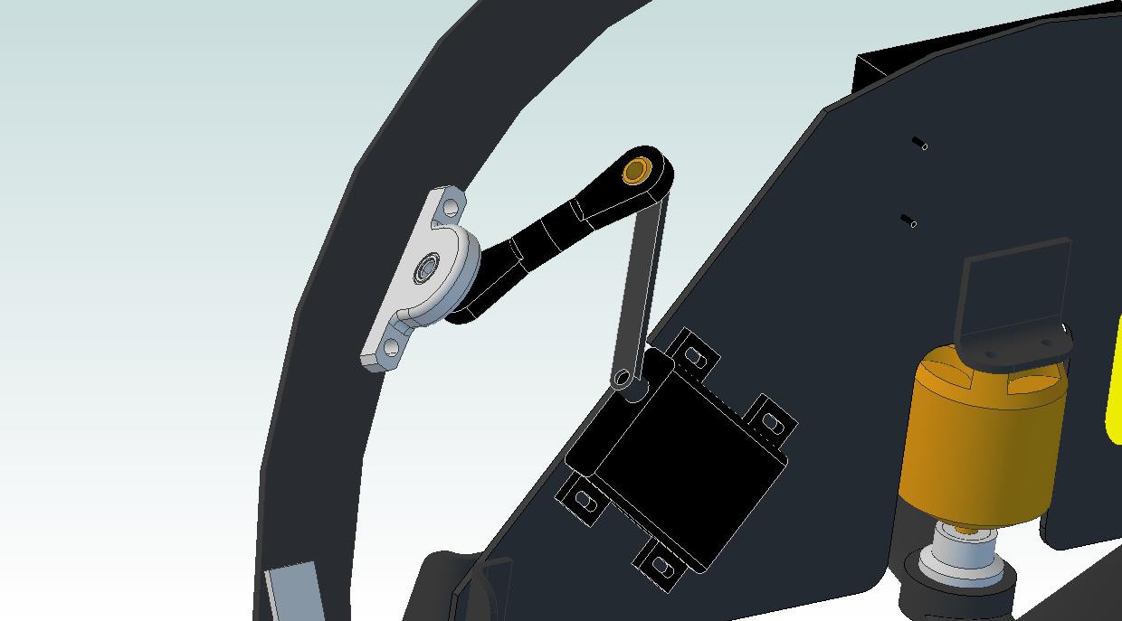
We're now on v06. I switched theta servos several times, so if anyone is looking for solid models of 'em: check the Dropbox repo. Accuracy not guaranteed, since they're based on manufacturer's prints (and they don't like to publish shaft locations for some silly reason).
A few notes on the image above:
- That's a Hitec HS-7115TH servo originally designed for installation in RC wings. Titanium gearset, double ball bearings, programmable, etc... seems to be a pretty legit unit, although it's not particularly cheap. 50 oz-in with 0.10s 60 degree actuation (at 7.4vdc) better be enough, because it's about the best I can find in this form factor.
- I originally recess-mounted the servo with a matching cutout on the CFRP plate; that would have made the drive axis in line with the center of the plate (well, it would be off by 0.8mm, but close). Switched it up to a spacer design for a few reasons:
- Spacers (not shown) will give us some leeway on alignment. I'll also slot the CFRP holes perpendicular to the slots on the servo itself so I can tweak servo angle if necessary.
- Even though the plate is really strong, I was a bit concerned about taking a huge chunk out. I think doing some basic calculations would help this, but.. it hasn't happened. Oh well.
- I found tiny nice looking pillow blocks that seem like an easy solution for the pitch ring mounting point, and they've inherently got a 3/8" offset (plus 0.8mm). I'd like to come as close to matching that as possible to avoid too many alignment issues.
- Speaking of alignment: if you pull apart the solid models of the pitch ring and motor plate (specifically, the extrude cuts and associated sketches that define the servo and pillow block mounting points), you'll notice that I based their angle off of a radial reference line that starts at the center of the plate or ring. Seems like I want the rotational axis of the servo to be in line and parallel to this line, so.. it is.
- I'm impressed that the program was able to model the linkage rod ends so well. They're actually little assemblies: the brass balls are separate from the nylon housings, and they're connected using a single constraint in the assembly. Makes it really fun to move the plate back and forth to check range of motion and interferences.
Overall thoughts: this linkage setup will require a custom-length servo horn, but all of the other parts are off-the-shelf. The servo can be programmed to allow 180 degree rotation, and using that whole range will give us a theta rangeability of +/- 30 degrees: should be waaay more than I need for basic stability control.
-
Stepping up my solid modeling game
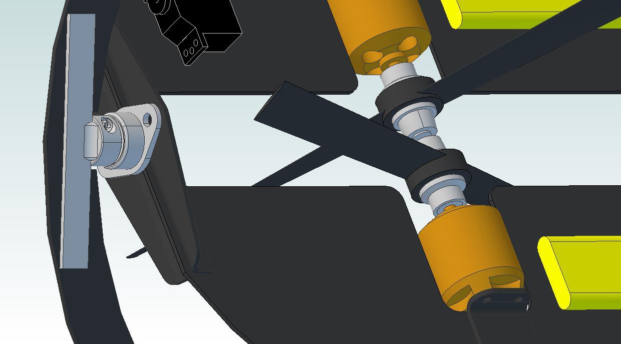
05/18/2014 at 14:53 • 0 commentsNow that I've got some parts in hand, I figured it was time to increase the accuracy of the solid model. If you're interested in the actual part files, check the Dropbox repository (and let me know if you need a non-Cubify format); we're on to version 05 at this point. My revision control scheme isn't terribly sophisticated; when I get sick of making changes to a model, I pretty much copy the folder and create a new version.
![]()
A few notes, as usual:
- Since I've got them on my desk, I measured up the brushless motors, props (and associated rotating hardware), and ESCs; their models are accurate in critical dimensions to ~0.1mm or so (although my calipers are pretty crappy).
- The bearings and shaft couplings are solid models downloaded from McMaster. Note that the shaft couplings have a welded-on aluminum bracket; I'm an almost-passable welder on reasonably thick carbon steel, but I sure do suck with aluminum so I'll be getting this done somewhere.
- The motor brackets and bearing brackets are made from 1.6mm CFRP angle stock. Ideally, I'll get these bits waterjet cut so they look pretty, but I might just trim 'em myself to keep cost down.
Next steps in the solid model:
- Theta servo linkage
- Rho bearings and brackets
- Rho servo shaft and mounting scheme
- Frame improvements
The waterjet guys do a batch every 2 weeks or so; I'm shooting to finalize the design by the end of May, order the CFRP plates, and hopefully have cut parts ready to assemble by the third weekend in June. I'm doing everything I can to keep stuff inside the standard plate dimensions to keep cost down; at this point, I'll likely need one 24"x48" 1/32" sheet and one 12"x12" 1/16" sheet. Before anything gets ordered, real-world thrust measurement will happen so I can improve the accuracy of my weight target.
Comments, as always, are welcome.
-
Some bits and pieces arrive
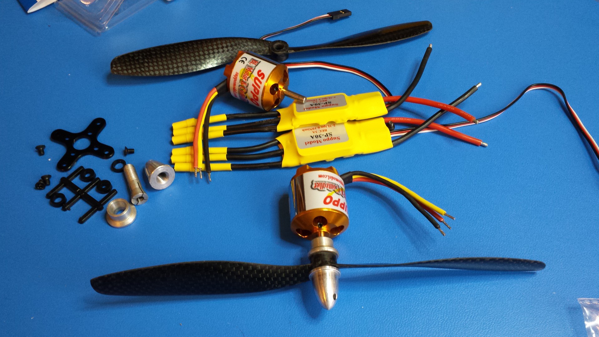
05/17/2014 at 21:58 • 0 commentsExciting times in Minneapolis--a few boxes showed up this week. Pictures and descriptions below:
Brushless motors, ESCs, props, and various bits of mounting hardware
![]()
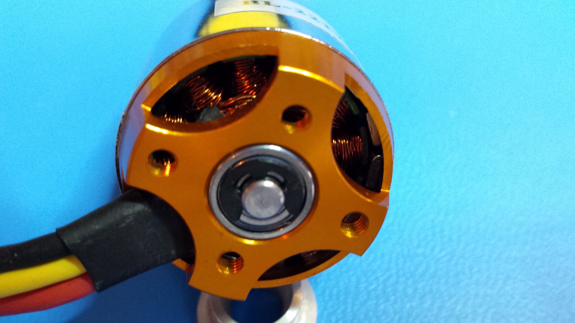
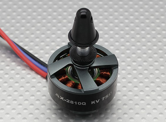
I'm new to the brushless/RC scene, so I'm not sure if these are great motors; they seem decent enough, but I haven't fired 'em up yet. One thing I didn't realize: the output shaft is attached to the case, so the white label actually rotates (it's what holds the permanent magnets). As such, the motors come with little X-shaped mounting brackets that screw in to (what I believe are) M3 threaded holes at the motor's base:
![]()
I'll probably design brackets that directly mate up with these holes rather than use the X-shaped dealies that came with the motors.
Otherwise, the props seem pretty well balanced (at least when I hang them off a screwdriver shaft) and the collet, washer, and prop nut all seem to be nicely machined. The ESCs are pretty dang small for handling 300 watts!
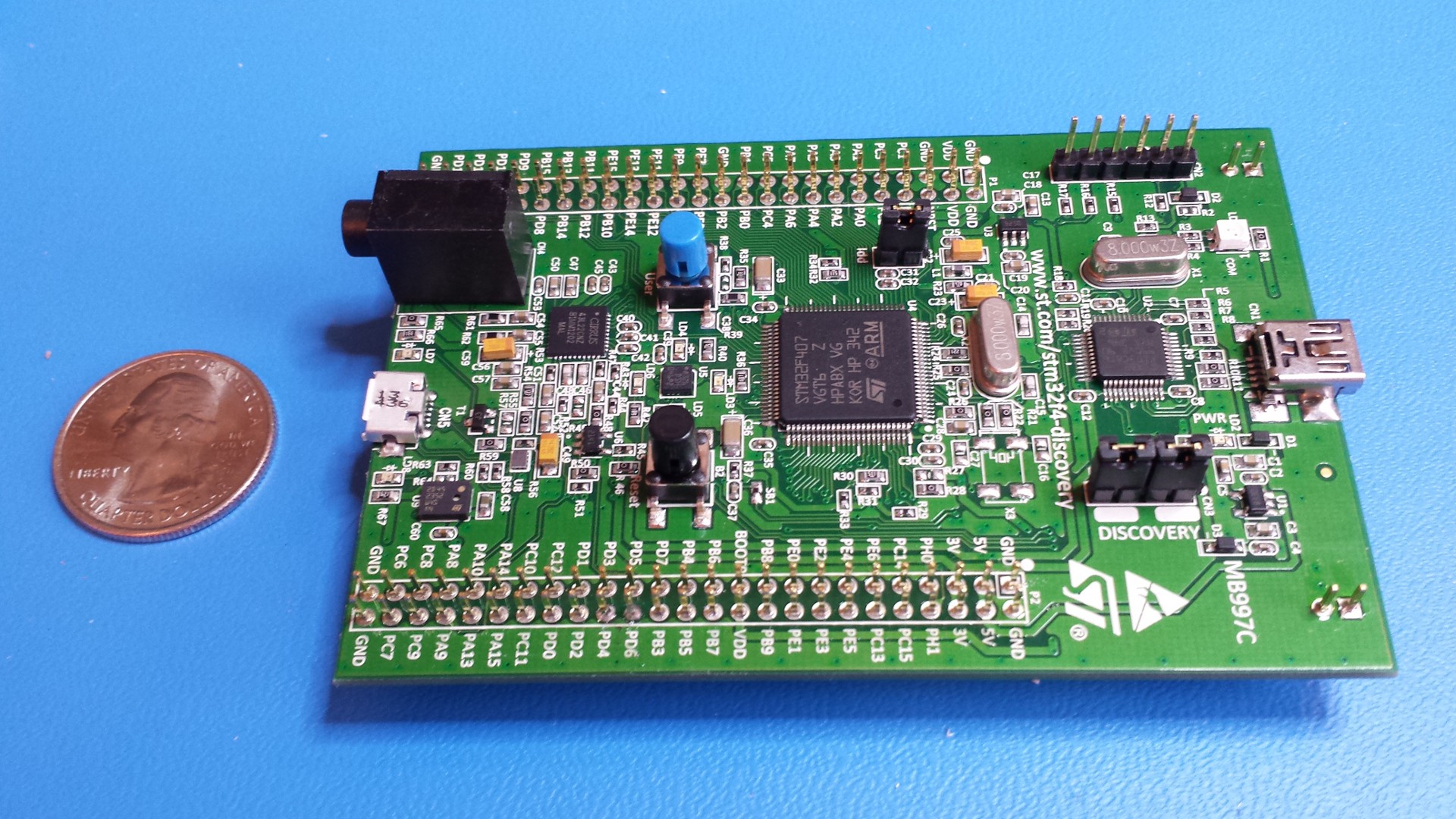
ARM Cortex M4 discovery boards
Suggested by the always-helpful Curtis, these were cheap and seem to be more than powerful enough for my needs.
![]()
They're also fairly light (my cheap-o scale says 36g), so they may end up in the final design. However, making boards is fun; I'd be able to shave a lot of size off if I designed my own, since these include stuff like an accelerometer (but no gyro, so it's not a ton of use for me).
CFRP plate
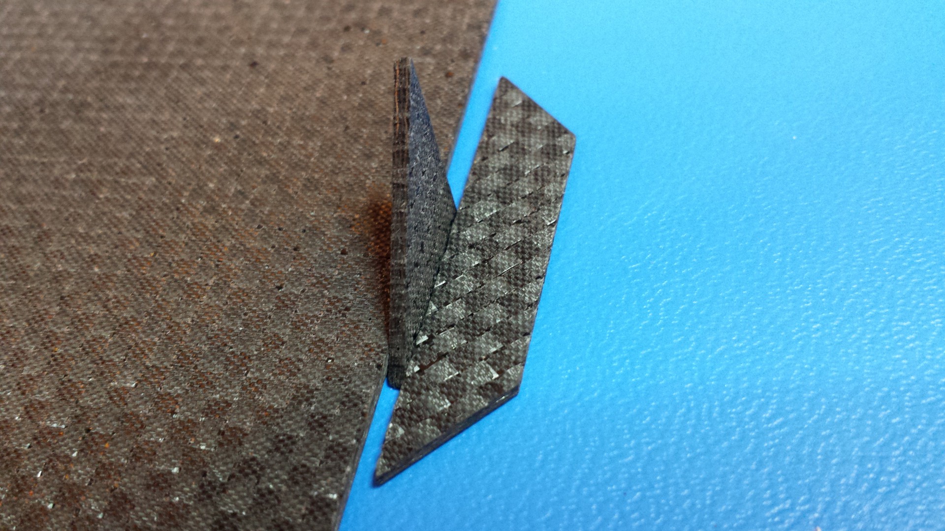
Two different samples of 1.6mm CFRP plate arrived; I think I'll use the slightly cheaper and less dense 0/90 double weave stuff. As previously discussed, I'll probably make most of the frame out of 0.8mm stock to save weight. I dropped by a local waterjet outfit Friday and had them try a few cuts:
![]()
Needless to say, the guys at the waterjet shop were damn impressed with the plate; sounds like lower quality stuff can have delamination issues. They're cutting with pure water, so I'll be designing around a 0.006" kerf. Incidentally, the test cuts were done on a machine set up for abrasive cutting, hence the slight draft angle.
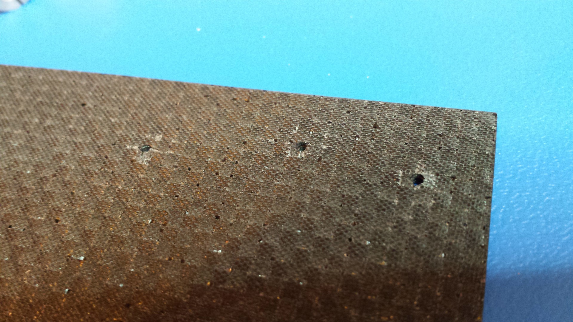
Normally one doesn't pierce CFRP with a waterjet setup due to the aforementioned delamination problem; however, they gave it a shot just for kicks:
![]()
Clearly there's a bit of localized delamination occurring, but it's minimal enough that I can probably design it into a waste section. Alternatively, they can start cuts from a hand-drilled starter hole.
Either way, the next test will likely involve a bit of Space Glue. I deliberately ordered CFRP plates with a textured surface, as I've read that this is best for epoxy work; I'll probably hit 'em with some 120 grit before trying a few different types of glued joints. Ideally, I need to be able to do lap joints and tee joints.
Oh yeah, and some aluminum rectangular tubing arrived too. No pictures of that because it's pretty basic.
-
And now, we play the waiting game...
05/08/2014 at 19:49 • 0 commentsInevitable, isn't it? We come up with fun project ideas, order a bunch of stuff, and spend the next week anxiously watching a collection of UPS tracking numbers, agonizing over whether or not we bought the right components. Here's what I've got coming my way (you'll be happy to know I figured out HaD's text editor, so the links are inline):
- Contra-rotating propeller assembly: I ordered this before changing the design around a bit, and it's still not here (since I accidentally ordered it from HK's "global warehouse"). Probably still useful, I'll definitely check the motor thrust and so forth.
- Electronic speed controllers for above: 25 amp rating means they may not be adequate for the final design, but they'll be handy for testing purposes. Also, cheap.
- CFRP Sample 1 and CFRP Sample 2: The local waterjet outfit I'll likely use wanted a few chunks to try. I also want to fiddle around with it a bit; might try to rig up some kind of a cheap bend test apparatus. Incidentally, last night I ran the numbers on the current GB design and it looks like this stock will likely be too thick to hit my weight requirements. Oh well, it will still be useful for SOMETHING.
- ARM Cortex M4 eval boards: I could have sworn I ordered these from DK late last month but now I can't find an email record. I'll give it a few days and get another one if necessary.
- Brushless motor for thruster: Based on extensive use of the FlyBrushless database, I've pieced together what I believe could be a good motor for the GB thruster assembly. The site does a fair amount of real-world testing using props and a DIY thrust gauge, and it looks like these units (combined with the props I ordered below) could get me the 1kg thrust each I'm looking for.
- Props for the above thruster: Again, based on FlyBrushless tests. Pitch is a bit greater than the FB tests (4.5 vs 4), but this will give us a decent baseline. Hopefully.
- ESCs: Yeah, I have 25 amp units on the way, but it's kinda tough to say when those will arrive. I bought a set of 30amp units to be on the safe side and to give me plenty of headroom with the motors.
- Aluminum tube stock: Picked up a 4' length of this (one of the smaller sizes) to build a cheap thrust gauge. Discount Steel is right down the street, so I can grab this locally once they have it cut.
So... more updates to come when goodies start to arrive. I'm midway through the v04 CAD model, which integrates actual dimensions of the above parts (along with some other changes) into the design. I did a few tests on the space glue that showed up earlier this week and it seems like good stuff; we'll see how well it bonds to roughed-up CFRP plate.
Random gripe: The RC world is a pain in the ass. Motor specs are ostensibly designed to make selection easier, but looking at posted real-world results of thrust measurement, current draw, and V/RPM it's clear that they are often driven by the marketing department. Also, all the suppliers and brand names are new to me; the flashy graphics and bright decals seem to get in the way of substance. I get the feeling that a lot of brands are just relabeled, and all of the stuff actually comes out of the same factory. We'll see how the first run of tests goes.
-
Real-World Thrust Testing
05/07/2014 at 19:41 • 2 commentsI think it's time for some science experiments. As described in detail by Robert W. Deters and Michael S. Selig in their 2008 conference paper on props (http://aerospace.illinois.edu/m-selig/pubs/DetersSelig-2008-AIAA-2008-6246-MicroProps.pdf), it's tough to come by good data in the RC world. The static thrust calculator I found seems legit, but... I need real world data that I can trust. Also, as mentioned in the comments for the previous project log, coaxial contra-rotating propellers are a pretty tough aerodynamic problem to solve on paper.
Since the world loves pictures, here are a few from Forrest Frantz' great thread on copter design (http://diydrones.com/forum/topics/build-your-own-copter-part-ii):
![]()
![]()
I will not be testing anywhere near that many combinations unless the RC motor and propeller delivery truck happens to break down in my front yard. In any case, here are my objectives for this minor but somewhat interesting tangent:
- Set up a rig to quantify motor/propeller performance
- Static thrust
- Total power consumption
- RPM
- Test a few single motor/propeller configurations to cross-check the calculations from the previously linked static thrust calculator, and develop RPM/thrust/power maps for these configurations
- Test a contra-rotating configuration using the above combinations, varying propeller spacing in addition to thrust
- Block part of the contra-rotating propeller assembly to simulate actual installation in the GimbalBot frame
Just a brief post for now. I'll throw together a basic sketch with requirements for the rig at some point and get into detail on its construction. Hint: it's going to be cheap.
- Set up a rig to quantify motor/propeller performance
-
Napkin calcs + a first run at componentry
05/06/2014 at 14:47 • 6 commentsNapkin calculations: often done at a bar, on a napkin, with a marker (or a toothpick dipped in Angostura bitters). In this case, it's time to do some very rough calculations to figure out if GimbalBot is destined to fly. To do that, I've started finding various components and tracking their weight; see the GimbalBot BOM for this info (I'm keeping it separate from the finances spreadsheet, since the BOM will ideally only track stuff that goes into each version rather than overall project expenses).
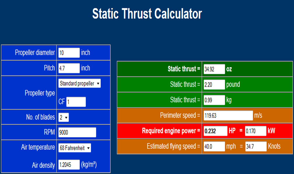
First, how much thrust do we need? Diving in to the multirotor community, there are a few calculators out there that estimate static thrust based on propeller design (pitch, diameter, and type), air density, and RPM. They also spit out motor power requirements, presumably assuming 100% motor efficiency. I putzed around with this one a bit (screenshot of my ballpark configuration shown with a link below that):
![]()
http://personal.osi.hu/fuzesisz/strc_eng/
Why 10x4.7 on the prop? Seems like a common size available in the quadrotor world. Why 9000 RPM? Well... based on my calculations, the motors I've found seem like they'll hit that given the required power calculated above:
![]()
After playing around with HV stuff a decent amount as a kid, I got confused initially by the 750kv designation (that's scary!). Turns out for brushless motors, that's a key spec: RPM per voltage. In my case, driving this motor at 12vdc should give me 9000 RPM, assuming I stay under its maximum power rating of 333 watts (well, that's at 11.1 volts, so let's call it 350W). Based on the prop loading to produce the thrust calculated above, it seems like I should should have power to spare. Thrust increases dramatically at increased RPM; going up to 10,000 with the prop shown above increase the thrust from 990g to 1230g at 234W motor power; provided I can give the motor 13.3 volts, this should be attainable. (side note: assuming the tool calculates thrust with respect to Earth's gravity, I should probably be thinking about this in terms of Newtons: in that case, the above example gives us 9.7 N and 12.1 N thrust, respectively).
So... to use this information for GimbalBot design, we have to make a few big assumptions:
- Running two of these prop/motors coaxially in a contra-rotating configuration will sum their respective thrust outputs.
- The interference caused by the thrust plate, pitch ring, theta servos, and slip ring getting in the way of the propellers won't be too detrimental to effective thrust output.
To be somewhat conservative (hopefully conservative enough), we'll assume that the stuff blocking the propeller will reduce it's total thrust by 20%. Ideally, we'd do some fancy CFD modeling to see if this is the case at different flow velocities; given my lack of experience with these tools, I'm guessing I'd screw up a mesh design and get bad data out. Either way, 10k RPM - 20% can round up to 19.6 N, or an even 2 kg of static thrust.
Step one: make GimbalBot lighter than 2kg. Step two: Try to improve the power:weight ratio further. It seems like a lot of folks in the quadrotor community strive for a 2:1 thrust:weight ratio, but I think as long as I stay above 1.5:1 I should be in decent shape, at least for slower flight. Remember, I'm not trying to build an aerobatic drone carrying an FPV camera; I just want something that hovers nicely.
On to the next issue: I need to get 14vdc at 20+ amps (based on the 234 watt calculation + some fudging) to each motor to hit 10k RPM on a 10x4.7 prop. Call it 50 amps total with the theta servos. Trouble is, commercial slip joints seem to be sized for higher voltage and lower current loads. My excellent cousin Curtis suggested sending higher voltage through the slip ring and dropping it for the motors. I've found a few tiny DC-DC converters on Digikey that might do the job, but I might also keep an eye out for lower-kv brushless motors that are intended to run at 48+ vdc. That means the speed controllers need to be properly rated, and the theta servos (and RF receiver) will still need 6vdc. Hmm.. More to come. Suggestions, as always, are welcome.
-
Gimbal Actuation/Notation Convention
05/04/2014 at 20:25 • 0 commentsFirst, a TL;DR picture illustrating the ramblings of this far-too-long log entry:
![]()
Color scheme:
- Orange: CFRP frame
- Red: brushless motors
- Gray: aluminum motor brackets
- Dark gray: servos
- Purple: radial/thrust bearings
- Brown: propellers
- Cyan: thrust plate
- Yellow: pitch ring
- Green: slip ring
I've had a few thoughts since my last post, most of which are related to actuation of the gimbal axes. As I discussed previously, the gimbal mechanism will have two degrees of freedom: rotation around the GimbalBot's vertical axis, and rotation perpendicular to that axis to control what I referred to as the 'severity' of the corrective thrust vector. I also mentioned that the travel time from one control point (rotation angle + severity angle) to another should equalize both degrees of freedom so that the gimbal doesn't hit its rotation and wait for the angle to be right.
We'll call rotation of the gimbal around the GimbalBot's vertical axis Rho, while severity angle (thrust vector direction?) with respect to the vertical axis is Theta. Theta is zero when the thrust is in line with the GimbalBot's vertical axis, and Rho is zero at an arbitrary point around the GimbalBot's body (i.e., we'll usually just consider it relative to a previous value). To move from one control point to another, the actuator control circuitry needs to determine the shortest possible path; also, the path that minimizes severity angle (err, Theta), since we'll assume our fancy brushless thruster motors can't modulate speed very quickly (don't even think about suggesting swash plates!). Either way, in some cases the controller will move Theta through 0 degrees, and in other cases it won't. For example:
- Theta is 15 degrees, and Rho is 0. The control system needs to increase Theta to 20 degrees and rotate Rho to +30 degrees. To accomplish this in one second, GimbalBot would elevate Theta at 5 deg/sec and rotate Rho at 30 deg/sec.
- Theta is 15 degrees, and Rho is 0. The control
system needs to keep Theta at the same value but rotate Rho to +160
degrees. In order to minimize the off-axis thrust (that would presumably
cause a severe flight path upset that would require additional
correction), Rho would rotate at -20 deg/sec and Theta would rotate at
-30 deg/sec.
So how do we do this? Should the control system, knowing the maximum actuation speed for Theta and Rho, attempt to optimize for minimum A --> B actuation time? Or should we limit the maximum Delta Rho to some arbitrary value like 90 degrees, past which we flip-flop Theta instead of performing a larger Rho change? Either way, one thing is clear: we want Rho to only be relative to previous values of Rho. Eventually we'll tie it in to some arbitrary direction so GimbalBot has a definite 'front' and 'back', but in general it will need to be able to spin freely. That gives us a significant design constraint.
Rho needs to rotate continuously through 360 degrees, otherwise GimbalBot's response rate to disturbances will vary depending on its absolute rotation. I suppose we could just use really long wires that eventually get wrapped around the gimbal after a few minutes of flight time (kidding), but the real solution here is to use a proper rotary electrical joint, generally called a slip ring (http://en.wikipedia.org/wiki/Slip_ring). Hmmm...
Where does the slip ring get mounted? Well, looking at the v01 sketch, the rotary actuator that controls Rho could be mounted above the gimbal assembly, and the slip joint mounted directly opposite at the very bottom of the unit. Provided the slip ring has a reasonably small cross sectional area, this hopefully won't disturb the thruster's air flow too much. Electrical wires to the stationary side of the slip joint would run around the perimeter of the frame and need to be nicely tucked -- again, to minimize air flow disturbance to the thruster.
So this might end up constraining our design a bit, as slip rings are only available in certain sizes and current ratings. Specifically, I could see there being better weight:current rating and cross sectional area:current rating designs; we want to minimize both of those ratios without building something TOO big. In any case, what exactly do we need to get into the continuously rotating portion of the gimbal, from an electrical perspective?
- Thruster: I'm planning to use two brushless motors of some type (probably, as Curtis suggested, from the quadrotor scene). We'll need to give them power and individual control signals, since their relative rotation can be used to affect the rotational orientation of the device (NOT to be confused with Rho; we'll need another Greek letter for this, probably). Assuming I mount the electronic speed controllers on the gimbal plate itself next to the motor, that means four conductors total: ground, power, and two signals.
- Theta control: Theta doesn't need to rotate through 360 degrees (thank goodness), but it does need to be mounted on the gimbal ring that can rotate freely through the slip ring. Additionally, I'm hoping to use an opposing pair of small servos for Theta actuation; that will improve the assembly balance and reduce the torque transmitted around the ring itself. So... assuming the servos need to be controlled independently (so we can tweak starting position and so forth), that's another pair of signals assuming they share power with the thruster motors.
- Other
stuff? Will I need encoders? If Rho control uses a servo modified for
continuous rotation, it will need a shaft encoder to return relative
position; however, that can be mounted on the GimbalBot frame. Will I
need position sensing for Theta? Using servos should keep that
self-contained... we'll go with 'no' at this point.
Six conductors. Seems like that slip ring would get spendy, or at least large. More importantly, unless I use a mercury-wetted device, I'm guessing the carbon brushes inside a slip ring introduce at least some electrical noise. Will that cause issues with the servos or thruster RPM control? I'd rather not have to worry about it. What if I just send power at sufficient amperage through the slip ring and run the signals through a short-range RF link? I could put a beefy filtering cap on the receiver circuit to minimize noise on its power rail, and low power RF stuff should be pretty small and simple (while being plenty fast).
So here's the question (amongst many others): if I go wireless, what's my protocol? I'd prefer to use off-the-shelf stuff for simplicity. I've heard great things about Xbee; plenty of bandwidth. Will the continuous rotation cause issues with RF signal polarization angle? Can't afford to lose signal at specific Rho values! What about processing: should I put an ATtiny (or some other small microcontroller) on the gimbal itself to convert the wireless data stream into discrete servo outputs?
Oh yeah, motor details: Rho actuator will likely be a brushless motor with an encoder and a gearbox, or a servo (if I can find one that's nice and symmetrical). Added bonus if it's got a built-in thrust bearing so I can directly run the shaft into the unit. The servos need to be sized for speed and torque rating; note that I haven't done anything with the linkage yet, either. I might add another pitch ring perpendicular to the first (supported with gussets, etc) and the servos will run their linkages into that. Either way, I'm guessing I'll need some kind of linearization equation built in to the servo actuation since the linkage will be offset. Anyone that knows something about linkages care to weigh in?
As always, feedback is more than welcome. I've got a bit of experience with servos, but haven't putzed around with short-range small-scale wireless stuff. Or brushless motors. Or linkages. I don't want to spend the next month chasing down connectivity issues and pitch ring binding problems!
-
v01 sketch
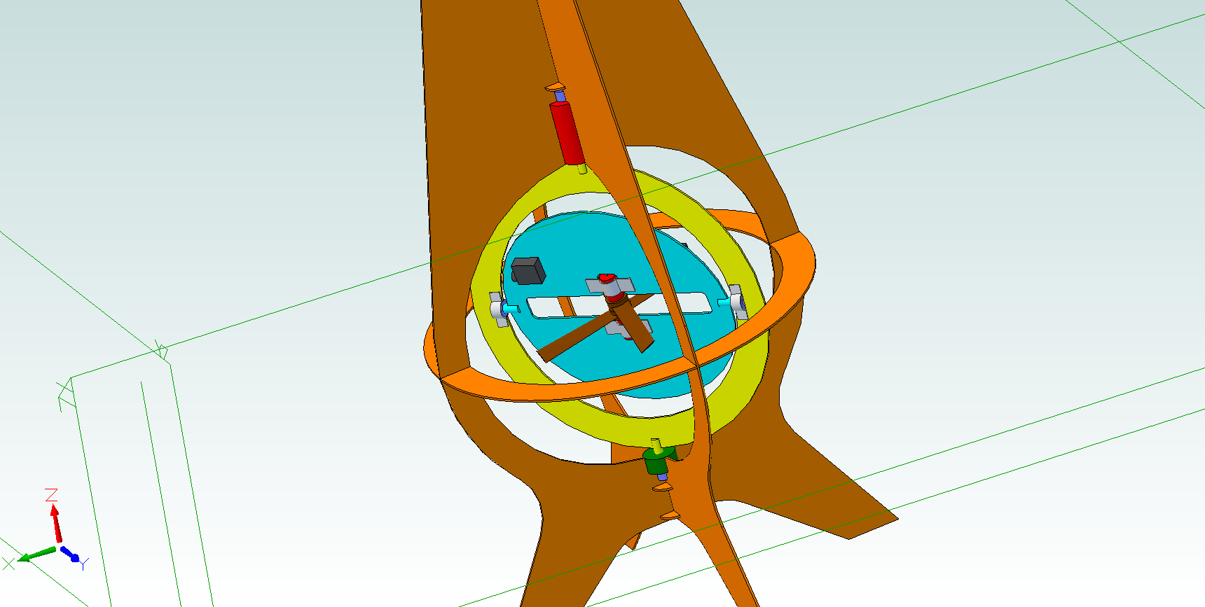
05/02/2014 at 04:08 • 2 commentsI started thinking back to my brief but thoroughly enjoyable experience with Kerbal Space Program and remembered a tip from the wiki: the thrust vector should be in line with the center of mass. In my mind, that means a gimbaled fan needs to be designed to apply force directly to a point along the center axis of the structure. Their site has a better (albeit brief) explanation here: http://wiki.kerbalspaceprogram.com/wiki/Center_of_thrust
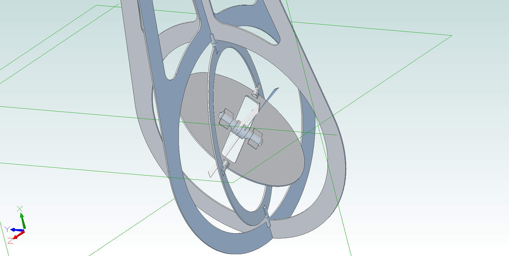
So how does that happen? I putzed about a bit this evening and put together some rough sketches. Nothing based on real-world dimensions, but I tried to keep assembly constraints correct so that I can rotate the thruster about to check interferences and so forth:
![]()
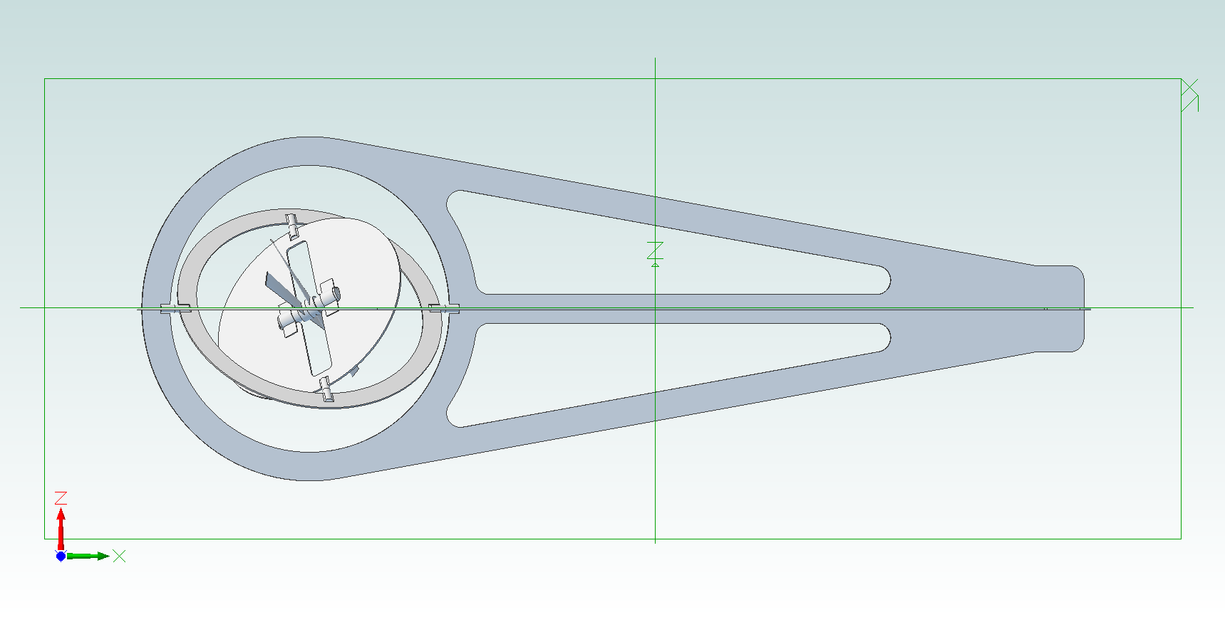
Zoomed out version lying on its side (remember, the arrow points up!):
![]()
We'll call this design GimbleBot_v01. A few notes:
- No actuation shown (or considered yet). Direct driving the two gimbal axes would be pretty sweet, since linkages would be an extra thing to go wrong. Also, if the gimbal servos are both mounted on the rigid frame, the inner gimbal drive would have to compensate as the outer ring rotated. Does that make sense? Seems like it would be trouble, both from a control perspective and from a physical capability standpoint (i.e. I would probably end up limiting range of motion).
- In the second picture, the flat area at the point of the triangle would hold sensors, electronics, that sort of thing. I did recently order a few brushless motor controllers; they're designed for the RC world so they're tiny, and I figure those could be mounted directly adjacent to the motors on the motor mount disk. I also ordered an off-the-shelf contra-rotating propeller unit, which (if it seems like the v01 design holds water) is already obsolete. Oh well.
- Here's a fundamental change: previously, I hadn't really pieced the gimbal together in my head; well, actually, I thought of it more like a rocket gimbal, with all the 'guts' at the bottom and some type of a ball-and-socket-like interface to locate the gimbal with respect to the main frame. As such, I planned to have a definite 'pitch' and 'roll' axis (at least, that's what I think I called them in the previous post). This design is more like a polar coordinate system; the outer ring rotates around the axis of the frame (and, if the props are really centered, the 'center of thrust'), and the inner ring elevates the thrust vector.
- That probably wasn't clear. In other words, when the craft is in an unstable state (like when it's hovering and gets pushed), the outer ring rotates around the frame axis to determine the 'correction thrust direction' while the inner ring rotates to change the 'correction thrust severity'.
- This could have weird control implications. When the control algorithm tells the actuators to change the thrust vector, relative actuation speed of the two actuators will dramatically affect how the craft responds. I wonder if control loop oscillation would show up as helical flight? Maybe balancing the actuation speed of the two gimbal axes is another critical factor: will they need to reach their respective set points at the same time?
- I haven't worked with the stuff in the past, but this design kinda built itself for laser-cut CFRP panels. The model shows them at 2mm thick; presumably I'll need to adjust that here and there. Additionally, the frame construction in the model was simplified to have a base frame and two half pieces that are stuck on; for the actual model, it would make sense to cut opposing slots in two base pieces that interlock for additional mechanical strength. Also, gussets. Glued gussets. In any case, I'm guessing CFRP is the only readily available material that will hit my (as of yet unknown) strength-to-weight ratio constraints.
Nothing finalized about this, even for v01; I've just found it's easier to visualize stuff on a computer screen, and 3D modeling assembly constraints make it easy to drag rotating bits around to see how they look. Feedback?
-
First Steps
04/30/2014 at 22:48 • 0 commentsSo... here we go, the project has been published. A bullet-list-brain-dump of what has been running through my head (minimally edited, but that's probably best at this point):
- Basic design. I want the unit to be radially symmetrical; to cancel the torque from the propeller, that means contra-rotating blades. Taking a cue from my excellent tiny remote control helicopter, I hope to use relative motor speed of the two props to control yaw.
- That brings up an interesting point: which way is up? What is forward? In my extremely rough sketch, I defined roll as rotation along the propeller and body axis; already I have violated this convention by calling it 'yaw'.
- Since the device will (if anything works as planned) hover vertically with the propeller at the bottom, we'll call rotation around the propeller's axis yaw. The two gimbal servos (or whatever gets used to tilt the thruster) will be designated Pitch and Roll, all relative to an arbitrarily point on the outside of the device that defines 'front'. Moving parallel to the ground with respect to the front (presumably by pitching) will be forward motion.
- Essential design considerations I should have figured out on a napkin before publishing this project:
- Thrust:Weight. Can I find an off-the-shelf contra-rotating propeller system (or design and manufacture my own) that can put out enough thrust to lift the entire device?
- Actuation speed. Will servos be strong and fast enough to tilt the propeller in its gimbal mechanism? Will the system only be stable if you leave it alone (i.e. there is some critical tilt angle beyond which it can't recover)?
- Instrumentation. How fast can I get a signal from a 6dof sensor? Is it fast enough to react and catch the device before it flips over?
- Control. What kind of hardware do I need? What's my control loop update frequency for the pitch and roll servos? What about motor speed control to keep the system from going into vertical oscillation?
- When will I stop spelling 'propeller' and 'helicopter' with an 'OR' at the end? Thanks, HaD, for the red underline in your text editor.
- Breaking down the parts
- Thruster
- Controls yaw using differential rotation of blades.
- Accelerates unit (a) axially for simple up/down altitude changes, or (b) axially and radially for tilt and roll.
- Ideally reversible; if the device takes off and lands upside-down (and flips in mid-air), it wouldn't need a huge landing apparatus that clears the thruster range of motion.
- Gimballed. As mentioned above, the gimbal actuators need to be fast enough to catch the unit after starting a pitch or roll; strong enough to accelerate the propeller/motor assembly (including counteracting any gyroscopic effect); have enough resolution to minimize oscillation while hovering; and be as light as possible.
- Controls yaw using differential rotation of blades.
- Body
- Light. Light, light, light, light, light. I originally envisioned a CF truss system or hollow CF tube with milled holes. We'll see what makes sense.
- Reasonably strong to survive the inevitable crashes.
- Sensors
- Do I need an accelerometer AND a 3-axis gyroscope? My understanding is that gyroscopes help improve absolute orientation sensing during maneuvers, so I'm assuming I'll need both. Lots to learn here, undoubtedly.
- Response speed: see above. Same goes for resolution and range, I suppose.
- Actuators
- Will servos work? Do I need to use something with a better power:weight ratio? What about stepper motors? Or some type of linear motor? That could turn in to an extensive side project.
- Range of motion? I suppose that depends on linkage design.
- Lightweight (duh)
- Propellers
- Should I use ducted/shrouded fans? What will give me the best thrust:weight ratio? Can I get more thrust out of a smaller diameter using a ducted design? Should this be under the Thruster bullet (probably)?
- Motor control
- I've heard a lot of good about these fancy 'brushless motors'. Seems like they would fit the bill, as they're lightweight, powerful, and super controllable.
- Maybe something off-the-shelf (as part of a contra-rotating assembly)?
- Control system
- Speed? Bit width? Platform? I don't need a ton of I/O, but I do need the system to be fast. Should I try to do the control using integral math, or should I spec the processor to handle floating-point calculations from the sensors? Again: lots to learn here. I've got a bit of experience with ATtiny 8-bit controllers, but I'm guessing they're a bit underpowered for this application.
- Remote control system: I suspect the user controls will be fairly abstract in the control scheme; they'll bias the control algorithm but won't directly control servos or motors. More learning! At this point, range isn't a huge concern.
- Power
- Battery powered and fully independent of a tether is the ultimate goal. For the first tests, I won't try: if I can off-board the power for initial design, I won't have to worry nearly as much about optimizing overall weight of the other components (or worry about charging circuitry, battery 'care' circuits, or short run time). The first physical prototype(s) will be fully tethered and stabilized, at least until the basic stability algorithms are figured out.
- Thruster
Sounds like enough for a start. I'm going to think a bit more about this and maybe fire up some design tools to throw together a few rough models. I'd love some feedback, particularly from folks with the following experience:
- Quadrotors/hexacopters/DIY drones in general
- Inverted pendulum robots
- Brushless motor control
- High performance position sensing instrumentation
- Zach
- Basic design. I want the unit to be radially symmetrical; to cancel the torque from the propeller, that means contra-rotating blades. Taking a cue from my excellent tiny remote control helicopter, I hope to use relative motor speed of the two props to control yaw.
GimbalBot
Gimbaled thrusters, aerospace-grade adhesives, carbon-fiber-reinforced polymers, and inertial measurement units. This is a space project!
 zakqwy