-
Another common source for use of anaQuad120! Optical Drives!
04/09/2016 at 05:42 • 0 commentsanaQuad120 was mentioned in a previous log entry, here: https://hackaday.io/project/9984/log/33419-anaquad120 wherein a couple hall-effect transistors from a BLDC-motor can be used as an encoder. In the previous log, I used those from a 5.25in floppy drive. But there's a better source, and these could be easily used as a dial for most purposes...
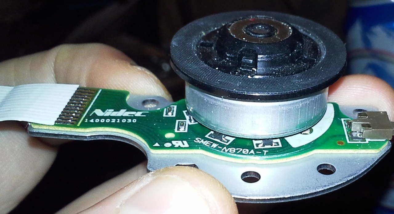
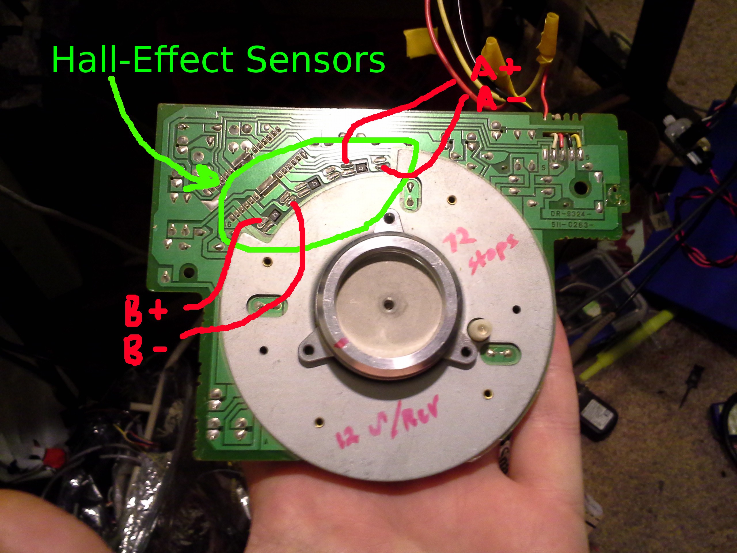
OK, so this is the spindle-motor from a DVD-drive. You can clearly see the hall-effecttransistors. Awesome. This guy wants to rest in something like 36 positions per revolution, but isn't nearly as "snappy" as the floppy-drive's spindle-motor. I haven't rigged it up yet,it just occurred to me, and it's a bit difficult to follow the traces under the motor. But, definitely doable, and its size/shape is highly-conducive to being used as a dial such as a volume-control or something.![]()
So, again, anaQuad120 allows for treating a system like this much like a quadrature-encoder. Most quadrature-encoders meant as dials are only 16 "detents" per revolution and cost around $3 apiece, so here's a source for 36-position encoders :)
There exist hall-effect sensors that output a digital signal... so it's possible that's the case, here, in which case anaQuad isn't necessary... regular quadrature-decoding would probably work (despite they're most-likely 120deg out of phase, rather'n 90deg). But, judging by the fact these sensors are 4-pin rather'n 3-pin, they're probably analog-output... and anaQuad would work happily with that, and likely increase the resolution from 36 positions per revolution to (was it 12x?) a few hundred (if somehow that's useful...).
Another thought, especially on the higher-resolution, this shaft could be attached to a motor's... And then you've got a few hundred positions per revolution.
-
LVMDS-continued
03/11/2016 at 15:21 • 3 commentsNOTE: 3-27-17... ~ 1yr later. Did I write this? It's gonna take a week+ to recall this mindset!
---------
So... first, I want to mention that quadrature signalling is used for communication... I don't fully understand the details, but I think it's used for FM radio transmissions in order to send the Stereo audio-data over a single transmission carrier-wave. So, in a sense, it achieves communication of *two* different data-streams over a single wire, at the same bit-clock...
This is a little bit different than that, I think, because its intent is to send *digital* data, and... two separate data-streams? Nah, too complex for me to figure out right now...
Back to the wired-realm, where there's a "clock" signal separate from the "data" signal(s)...
So, is this maybe better/faster than, say LVDS?
Well, one interesting discovery of this system is the fact that its "lock-step" design--based on a state-machine looking for comparisons--apparently allows it to determine the "position" regardless of its actually running in a lock-step fashion... What do I mean by this...? Using nothing but simple comparisons (e.g. from a comparator, or several?) between the four signals received at the receiving-side (+clock, -clock, +data, -data), a handful of comparators could emulate anaQuad2x... Looking at the outputs of those comparators a digital value is achieved representing the "phase" or "position" of the quadrature-signal.
Low-and-behold... LVDS inputs *are comparators*... so, maybe, one LVMDS signal combined with several LVDS receivers could actually give a somewhat digital output... in this case, I don't mean digital as in a single digital *bit*, but more like an entire *nibble* received within one clock-cycle. Take it a step further, the "lock-step" design requires a bit of processing (I think) to iterate through those comparisons in order to find the new "position"... so...? We have generally accepted that long-distance communication at high-data-rates is usually quite a bit slower than the processors/FPGAs/Logic receiving them... The receiver has a state-machine running at 8x the transmitted signal... Bam.
So, is this a good idea...? What benefit is there, really...? If LVDS is slowed to some maximum rate due to its ability to swing levels to reliably-readable values fast enough... then wouldn't this system (LVMDS) run into that same problem...? Wouldn't it limit the "nibble-rate" to that same limit...?
This is where I'm not yet certain... On the one hand, maybe the "nibble-rate" is limited to a full-swing signal... which, for anaQuad, would be the equivalent of a 90-degree positional-change... (Actually, this limitation is probably a good one for several reasons... first of all, it means that the signal "transition" will never exceed that of an LVDS signal "transition", so should work in the same electrical/physical conditions, and second, the "auto-positioning" of the system works to -135 to 180deg, but is a bit iffy around the 180 and -180 marks).
Anyways, plausibly, instead of using direct multi-level digital transmission, wherein each "position" represents a binary value, instead, maybe, use multi-level digital *change*... wherein each "position" represents a *change* in binary-value...
I haven't thought this whole thing through, completely...
As far as physical implementation in the experimental-realm:
I think reception of anaQuad2x could be handled by four LVDS receivers, or even just four (fast) comparators... I need to think this one through a bit, still... And, transmission...? We'll come back to that.
-
anaQuad Communication - LVMDS?
03/11/2016 at 14:52 • 3 commentsLow Voltage Multi-Digital Signalling...?
Maybe.
Imagine LVDS... I'll go with FPD-Link, as I've used it before...
First: You have a clock... typically a "bit" clock...
Then you have a data line (or several)... It's not so much unlike, say, SPI... (Clock/Data on separate signals).
Electrically, it's a bit different than SPI, in that, in part, LVDS uses *differential* signal-pairs...
Now here's where it gets interesting for anaQuad...
One of the more-difficult aspects of anaQuad is the fact that you need to "invert" the inputs... If you have a signal that's *not* centered at *ground*, then inversion is a bit difficult, requiring knowledge of the magnitude and offset of the signal. Even more complicated is *scaling*... I'll come back to that.
In my experiments, it was found to be surprisingly reliable *despite* this, but if you *didn't* have to do this--if the inverted signal was *part* of the signal--then it would be even more reliable.
So, back to LVDS... We have *two* wires for each signal... They are *differential*, meaning that one is essentially the inverse of the other. This is for several reasons, including increased noise-immunity *and* decreased noise-emission.
When this data's fed into a receiver, the receiver *typically* looks for... duh duhn dunnnnn... *crossover* of the two signals.
So now... that's *exactly* what makes anaQuad so much more reliable than I even expected when designing it with that goal in mind... it's looking for *crossover* of (various multiples of) the signals...
So, I mentioned *scaling* of the input signals... In order to achieve anaQuad4x, we have to use not only the *non-inverted* and *inverted* signals (used also by anaQuad2x), but we *also* need the two signals *scaled*... (I use signal*2, but that isn't *exact*, it's just *easy math* for the processor). But: Scaling (properly) *absolutely* requires knowledge of the DC-offset (and magnitude?) of the original signal... which, again, I just threw in a random value that was close, and it seems to work surprisingly well despite having-done. But, it would be *great* if the DC-offset was not in the picture... and, low-and-behold that's exactly what using differential signaling does for yah... removes the DC-offset. BooYah!
So, now... Could it be used as a *communication* method... similar to LVDS...? e.g. anaQuad4x can detect 16 different positions in a single cycle... Comparing that to LVDS, that would mean for every singular bit transmitted in LVDS (alongside the clock signal), 8 different levels could be detected.
Is this helpful...? I'm not certain... I'll come back to that in the next project-log...
-
anaQuad120
03/09/2016 at 09:24 • 0 commentsAlright, so here's the spindle-motor from a 5.25in floppy drive...
![]()
This guy has 3 Hall-effect sensors to sense the timing necessary to power the motor's windings. There are multiple North/South-pole magnets around the motor, so while these are spaced about 22.5degrees apart around the motor, they sense the magnets at 120 degrees apart.
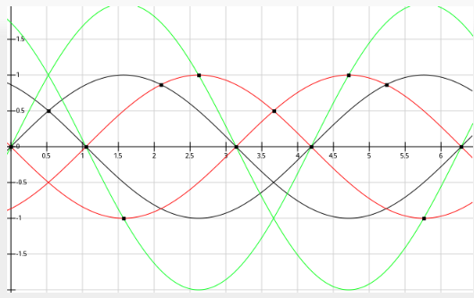
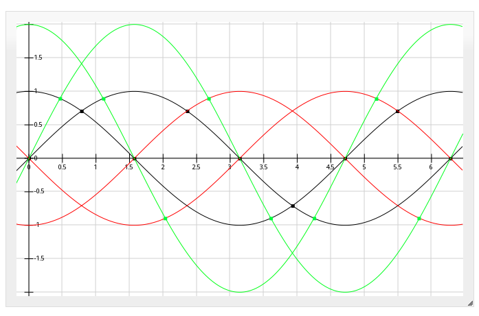
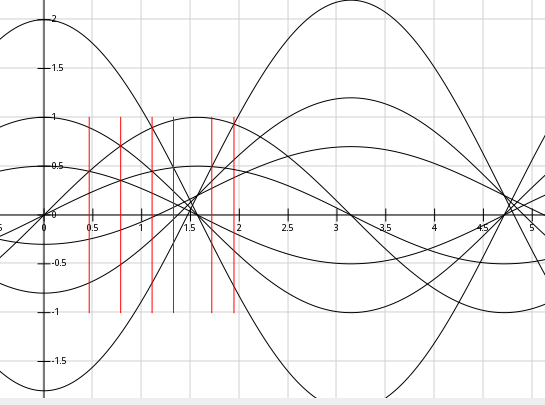
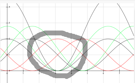
Low and behold, the crossover-detection method used in anaQuad can be made to work with two of these 120-degree phase-shifted signals (normal 'quadrature' signals are 90-degrees phase-shifted). Here's a plot of 120-degree phase-shift (two channels, and multiples thereof):
![]()
So, no problem detecting 12 positions per magnet.
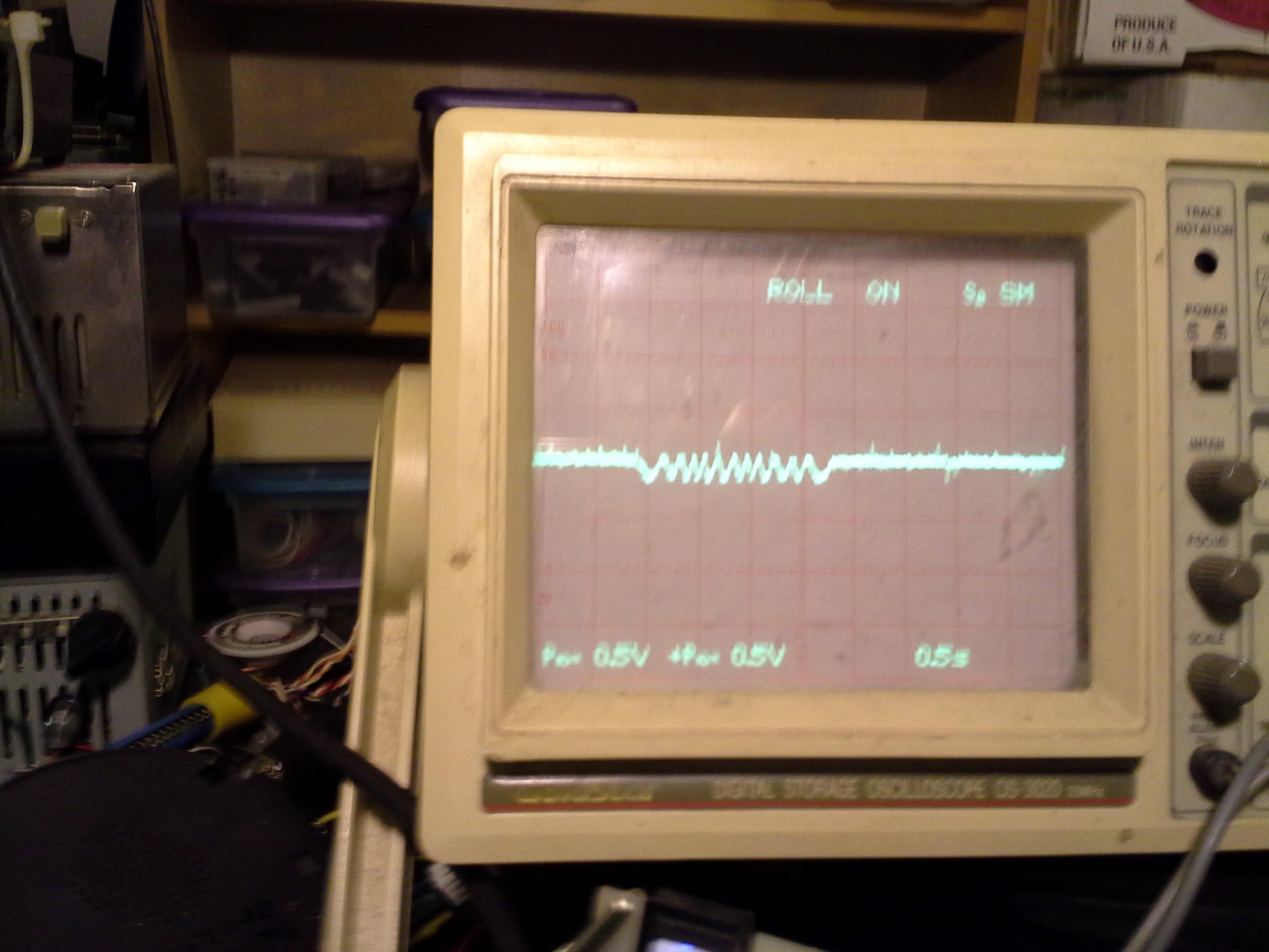
Here's the 'scope output of one of the Hall-Effect sensors as I rotated the motor through one full revolution:
![]()
So, there appears to be 12 magnets on the motor.
Thus, with the crossovers shown in the graph, above, there should be no problem detecting 144 positions per revolution. Since this kind of motor has quite a bit of momentum, as well as having particular positions it wants to stay in (kinda like a stepper-motor), higher resolution than that probably doesn't make a whole lot of sense... But, it's probably possible with additional multiples of the input-signals (just as anaQuad2x has been bumped up to 4x and could definitely go to 6x). This motor seems to have 72 positions it wants to rest in ("detents") per revolution...
These particular Hall-Effect sensors have two "outputs." The voltage *between* these outputs is what we're looking for. So, either, use an ADC with differential inputs (and preferably one that has scaling, as well, since 0.25V is pretty small), or we'll need to add some op-amps. (Some, especially newer, Hall-Effect sensors include those op-amps internally, so their single output might swing from 0V to 5V. Some other ones actually contain thresholding circuitry, so couldn't be used with anaQuad, just as there are quadrature optical encoders that only output square-waves).
This particular motor/driver combo has clearly-marked inputs: "12" "5" "G" and "C"... when powered with 5V and 12V, leaving "C" disconnected, the motor spins on its own. Connecting "C" (Control?) to GND causes it to stop, which is perfect for using this system as an input "knob" or whatnot.
So, there you have it. This guy might be handy for some sort of jog-dial or scroll-wheel, where you might want to spin it and allow it to spin-down on its own. Could also be used as something like this:
![]()
And, it might be a bit hokey, but it could, I suppose, be attached to another motor's shaft and used as an encoder (at which point higher-scaling might be handy).
-
almost plug-n-play!
03/08/2016 at 15:28 • 0 commentsPlugged in a computer-mouse's encoder, 48 slots -> 768 measurable positions.
This guy's a great (unintentional) test of the system's functionality despite somewhat dramatic calibration-error... The software's configured for a sine wave from 0 to 2.5V, (no software change from the previous experiment) and the encoder's outputting 1V to 3V (whoops), yet seems to be working surprisingly well.
-
6x... 24 steps per slot...?
03/08/2016 at 08:41 • 0 commentsIs it worth it...? We're at 4x as it is, 6x can be accomplished with the 4x cases (A, B, -A, -B, 2A, and 2B) and the addition of 4A and 4B (and maybe their inverses).
It appears that 4x isn't perfectly-spaced... in fact, the crossover of 2A and B is somewhere around the midpoint of 1/2 and 2/3 of the 2x case... so adding 4A/B to get 6x (rather than upping to 8x) kinda makes sense.
More code, is it worth it...?
(8x would require 1/2 A and 1/2 B...)
All this multiplication can be handled by shift, *if* signed-shift is defined (which is debatable). 2* is a single shift, which is no prob for most uC's, 1/2A likewise. 4*, though, would be two shifts... some uCs might implement arbitrary-shifting in a single CPU cycle, so 4* would be just as quick as 2* on those uCs, but e.g. AVRs have single-shift operators, so 4* would require two CPU cycles... and... 2* can also be implemented as A+A, which is usually a single cycle instruction... Of course, this all gets a bit more complicated if, e.g., the ADC's are 10-bit and the architecture is 8-bit...
And, again, I'm not sure signed-shift is well-defined and architecture-independent.
So, contemplations...
-
4x (16*numSlots) GO! + Video
03/06/2016 at 16:08 • 0 commentsOK, I managed to achieve 4x... that's four times the resolution achievable with a *digital* quadrature signal, or 16 discernible positions per slot.
That's right... My encoder has 72 slots, I can detect 1152 discernible positions per revolution!
Here's the basic idea... Look for crossovers:
![]()
From the ADC values of channel A and channel B, I'm using A, B, -A, -B, 2A, and 2B...
Thankfully, these are pretty simple math-operations... which means they're *quick*.
I was excited about the 'no-mult' case, described in a previous log, but that is incapable of detecting a position unless (nearly) every *transition*/crossover is detected *immediately*... which is darn-near impossible upon powerup, at the least.
So, instead, 2x... that's a simple enough operation. No multiplication necessary (still) just A+A or B+B, or even A<<1, etc...
This guy, well, I tested it from every possible starting-angle (integer values 0-360), and it had no problem finding its initial position (within the "hysteresis" range). That means it 'auto-aligns' upon power-up, and also means that if one (or several) transitions are somehow "missed" (while processing something else?), it will eventually find the actual location. COOL. No interrupts necessary. Excellent.
SO...
Here's a video. (maybe still uploading...)
-
Hypothesizing about init-state...
03/04/2016 at 13:51 • 0 comments(Update: Adding init-state testing results for the 2x case, at the bottom)
-------------
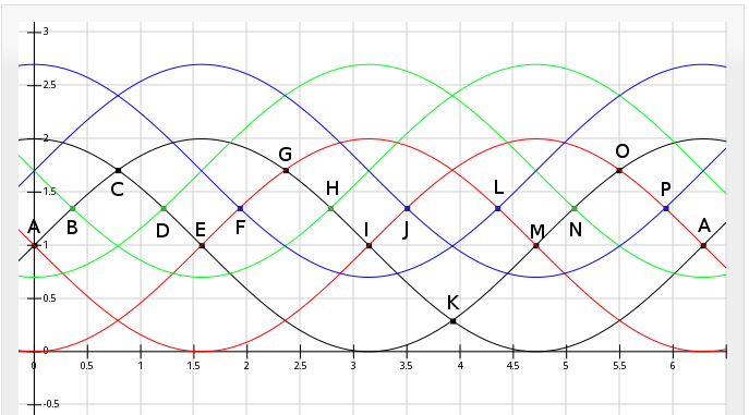
The "no-Mult" method for4x resolution, from the last log, has a "bug" of sorts... Rather, it's not exactly a bug, but an annoyance, anyhow.
Here it is, again...
![]()
If you power-up the system, and, say, it assumes you're at position A, but you're really just right of position H... the system will stick at position A. Whereas, in the 2x method, I think (but have not fully verified) that if you start at any position, it will automatically "catch up" to the actual position.
So, I've some hypothesizing...
![]()
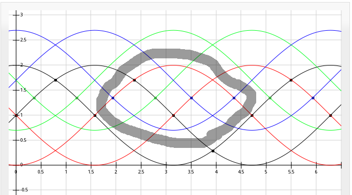
In the 4x "no-mult" case, there's an 'eye' where both endpoints are tested... and these two endpoints are *closer* than 1/2 period. I'm not sure why, but for some reason my intuition is telling me that's somehow related, or maybe responsible, for the inability to "catch up."
I highlighted the wrong "eye" here, for my 'H example'... but looking between the A state and the H state, it's quite apparent that the transition from A->B is not met because there exists an 'eye' between B and H. The transition from A->B requires testing that the black line is greater-than the green line, but to the right of the H-case, they've already crossed-over again. Their sampled-values show that the black line is less than the green line, so as far as "State A" is concerned, the B-crossover hasn't happened. Similar is true in the other direction, between P and J, preventing it from "catching up" in the reverse-direction.
Plausibly, the "eye" thing isn't the factor, but the "dead-zone" between them...?
Here's the 2x case, again...
![]()
Note that no "eyes" are less than one half of a period. So, I think, it's plausible to use the simple comparisons in the switch() statement to automatically iterate through from an assumed position to an actual position at least as far as 1/2 period away (maybe even a full period?), or "auto-align", or "catch-up".
Here's a 4x case I did early-on (with intentional "noise" to simulate offset and magnitude calibration-error)...
![]()
This one doesn't have any <1/2 period "eyes" either... so, again, I've a vague idea it might be possible for it to "catch up."
The problem with this one is it's centered around zero, whereas my ADC readings will not be. The scaling/shifting math necessary to zero it would add up quite quickly... multiplications of the signal, multiplications of the offset...
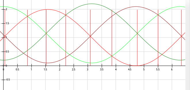
Now here's a case I was experimenting with just-now which gave me the "eye"dea (heh).
![]()
That "eye" is wonkey-shaped, but also <1/2 period.
This technique's not so great, anyhow, as it requires multiplications of fractions... so there's division or floating-point involved...
One might say "why you goin' to all that trouble to detect crossovers when alls you really need is to measure several threshold values...?"
Well, don't doubt that I've thought about it... I think I explained it earlier, but briefly:
The crossovers are *much* more noise-immune, for one thing. Also, as can be seen in the second-to-last image, it's relatively immune to things like calibration-error... if the offsets or amplitudes vary slightly between the two channels, or if the amplitudes aren't exactly the value I hard-code into the software, it should still work. There may be some positional accuracy error, but there shouldn't be a case where, for instance, a really large amplitude-difference (beyond whatever hardcoded-thresholds I might put in) would cause steps to go undetected. Also, note that I'm going out of my way not to look for "peaks", wherever there's a peak there's also a cross-over. That's *much* more detectable.
But, anyways, back to the "eye" thing... Again, I don't really know for certain that the 2x case even auto-aligns as I think it does... and actually I can't really think of a way to test (or otherwise verify) it, without testing every possible case. But somehow that "eye" sticks out to me as some sort of indication that it wouldn't be possible to auto-align in all (or as many) cases.
I've some other vague idea of something like riding a wave, or magnetic vs electric fields oscillating, or a few other such things... maybe traversing a circle. In the 2x case, it could be imagined that there are four (or two?) points on a circle which constantly stay the same angular-distance apart... Maybe a spring's attached between them, or something... The tension on that spring will never change. The 4x case centered at zero similarly. Or, how 'bout like the piston on a steam-engine... yeah. But the other cases are kinda like springs attached to separate gears... or planets with really weird orbits... I dunno, the intuition's there, the explanation's lacking.
------------------------
Init-state experiments with the 2x case:
Again, here's the graph:
![]()
The theory, again, is that this one is capable of automatically detecting the initial state via a few calls to the update() function.
It seems to be working, with a bit of "slop" inherent to the hysteresis of the system...
Locating our initial position from angle 224...
aE: adcVal_A=108, adcVal_B=610
aE:  lastPhaseState='A'
aE:   test1 = adcVal_A = 108
aE:   test2 = INVERT_CHANNEL(adcVal_B) = 101
aE:   test3 = adcVal_A = 108
aE:   test4 = adcVal_B = 610
aE:    test1 > test2. Advancing.
aE: adcVal_A=108, adcVal_B=610
aE:  lastPhaseState='B'
aE:   test1 = adcVal_B = 610
aE:   test2 = INVERT_CHANNEL(adcVal_B) = 101
aE:   test3 = adcVal_A = 108
aE:   test4 = INVERT_CHANNEL(adcVal_A) = 603
aE:    test1 > test2. Advancing.
aE: adcVal_A=108, adcVal_B=610
aE:  lastPhaseState='C'
aE:   test1 = adcVal_B = 610
aE:   test2 = adcVal_A = 108
aE:   test3 = adcVal_A = 108
aE:   test4 = INVERT_CHANNEL(adcVal_B) = 101
aE:    test1 > test2. Advancing.
aE: adcVal_A=108, adcVal_B=610
aE:  lastPhaseState='D'
aE:   test1 = INVERT_CHANNEL(adcVal_A) = 603
aE:   test2 = adcVal_A = 108
aE:   test3 = adcVal_B = 610
aE:   test4 = INVERT_CHANNEL(adcVal_B) = 101
aE:    test1 > test2. Advancing.
aE: adcVal_A=108, adcVal_B=610
aE:  lastPhaseState='E'
aE:   test1 = INVERT_CHANNEL(adcVal_A) = 603
aE:   test2 = adcVal_B = 610
aE:   test3 = adcVal_B = 610
aE:   test4 = adcVal_A = 108
aE:    No Change.
...found at 4 = 180 deg


Locating our initial position from angle 225...
aE: adcVal_A=103, adcVal_B=606
aE:  lastPhaseState='A'
aE:   test1 = adcVal_A = 103
aE:   test2 = INVERT_CHANNEL(adcVal_B) = 105
aE:   test3 = adcVal_A = 103
aE:   test4 = adcVal_B = 606
aE:    test3 < test4. Decrementing.
aE: adcVal_A=103, adcVal_B=606
aE:  lastPhaseState='H'
aE:   test1 = adcVal_A = 103
aE:   test2 = INVERT_CHANNEL(adcVal_A) = 608
aE:   test3 = INVERT_CHANNEL(adcVal_B) = 105
aE:   test4 = adcVal_B = 606
aE:    test3 < test4. Decrementing.
aE: adcVal_A=103, adcVal_B=606
aE:  lastPhaseState='G'
aE:   test1 = adcVal_A = 103
aE:   test2 = adcVal_B = 606
aE:   test3 = INVERT_CHANNEL(adcVal_A) = 608
aE:   test4 = adcVal_B = 606
aE:    No Change.
...found at -2 = -90 deg
So, it thinks 225deg is 180deg, and it thinks 226deg is -90deg... That's not so bad, right...? I figured it would be capable of detecting the position within 1/2 period, but of course some preference is given to the increasing direction since its test is run in the if() while the decreasing direction's test is run in an else(). And, though 225 -> -90 seems far-off (why not at least -135?) it makes sense in the sense that it's detecting in the reverse-direction, and 225 isn't far enough away from 360 to actually see the -135deg crossover. This is the hysteresis...
Again, this whole functionality is a nice side-effect that I wasn't at all expecting... but now that I know it's *possible*, it's something I'd like to keep in the higher-resolution versions... It might be a bit of a tradeoff I'll have to decide on. In the 'no-mult' case, it should run quite a bit quicker, but won't be able to auto-align like this. So, then, detecting the initial position at power-up might require an init-routine that involves actually moving the motor. (And, realistically, I'm not even sure how that routine would work). Also, it would mean that the update() function *must* be called at least once between *every* transition, there's no (or at least not as much) room for a missed transition to be caught-up-to. That isn't such a big deal, since, again, this whole system was intended from the start to be lock-stepped like that such that every transition would be detected in realtime. So, again, this whole thing is a bit of "would be nices" based on "completely unexpecteds" that are nice. But am I willing to sacrifice real-time speed-improvement over avoiding a complicated initialization-routine...? hmm...
Further, this auto-aligning experiment was run with "ideal" sine-waves with *known* magnitudes and offsets... what when they're thrown into a real-world system...?
On the plus-side of this experiment... I think I cleaned up the code quite a bit, and it should still be almost as fast...
The old switch-statement looked like:
//From A -> B: cA crosses c~B:  A > ~B
//From A -> H: cA crosses cB:   A < B
case PHASESTATE_A:
   //Advancing Right to B
   if( adcVal_A > INVERT_CHANNEL(adcVal_B) )
   {
      anaEnc_position++;
      anaEnc_lastPhaseState = PHASESTATE_B;
   }
   //Advancing Left to H
   else if( adcVal_A < adcVal_B )
   {
      anaEnc_position--;
      anaEnc_lastPhaseState = PHASESTATE_H;
   }
   //else, wait here...
   break;
which resulted in a lot of redundant-code (every case has a position++/-- and a PhaseState++/--). So why not move that stuff to the end...?So now it looks like:
//From A -> B: cA crosses c~B:  A > ~B   test1 > test2
//From A -> H: cA crosses cB:   A < B    test3 < test4
case PHASESTATE_A:
   //test1 = adcVal_A;
   SET_TEST(1, adcVal_A);
   SET_TEST(2, INVERT_CHANNEL(adcVal_B));
   SET_TEST(3, adcVal_A);
   SET_TEST(4, adcVal_B);
   break;
SET_TEST(num, var) is pretty much nothing more than "test<num> = var", but also makes it quite nice for debug-printout with some good 'ol preprocessing...:#define SET_TEST(num, var) \ ({ \ test##num = var; \ AE_DPRINT("aE: test" #num " = " #var " = %d\n", var); \ {}; \ }) -
Mwahahaha - No Mult!
03/04/2016 at 11:10 • 2 comments![]()
Seriously! Only addition/subtraction, and sharp easily-detectable crossovers for each position...
And one of the difficulties of multiplication (which was my original plan, e.g. looking for channel A crossing channel B /2) is the fact that the measurements are not centered at 0, so the offset would've had to have been accounted-for (and scaled?) in such multiplications...
Here we just compare between A, ~A, B, ~B, A+N, B+N, ~A+M, and ~B+M.... The offset is unnecessary (though the amplitude is, for ~...).
Again, per the original plan, there's the specification/expectation that the update() function will be called at least once per transition, so knowing which transition was detected last, the only math that needs be executed in each call is that of the two nearest transitions, so worst-case scenario appears to be detecting position F, so say from position G...
switch(state)
{
  ...
  case G:
   //G->H
   if ( (1.35*AMPLITUDE - channelA) > channelA )
   {
     position++;
     state = H;
   }
   //G->F:
   else if ( (1.35*AMPLITUDE + channelB)
              < (AMPLITUDE - B))
   {
     position--;
     state = F;
   }
   break;
  case H: ....
AMPLITUDE is a constant, so 1.35*AMPLITUDE is also constant (and, ultimately, an integer), so worst-case scenario, one subtraction and comparison for G->H, which fails, then one addition and one subtraction and a comparison for G->F... and, plausibly, some math-reordering could occur, as well...? Subtract AMPLITUDE from each side, maybe? (Not sure 1.35 is right... just guessing).
anaQuad!
Reliably increase your quadrature-encoder's resolution using an ADC (or a bunch of comparators?)
 Eric Hertz