-
Do You Need AnaQuad?
12/07/2021 at 19:30 • 11 commentsYet another draft not submitted... It's now May, this was written in December......
....
AnaQuad's design is for some very specific use-cases... I should put more effort into highlighting that.
Not long ago, using a [digital!] quadrature encoder at all was such a CPU-intensive process that pretty much the only reasonable way to do-so in any high-speed/high-resolution application (CNC) required a chip dedicated to counting quadrature... (e.g. HCTL-2000-series). This was pretty much the /only/ fast-enough solution to assure no steps went missed.
Today, even a lowly 8bit RISC microcontroller can be put to that task without hiccuping... BUT, doing-so with /any/ processor running code, it's *extremely* important that the quadrature-decoding code be executed fast-enough and often-enough that no steps can possibly be missed.
This is where things get tricky. It's not only a matter of making sure the quadrature-handling code is fast and called often, but also a matter of making *certain* any other code running on the same processor can never delay it too much, e.g. during a rare case like an interrupt occurring at exactly the wrong time.
Thus, one obvious technique is to put the quadrature-handler *in* a high-priority edge-triggered interrupt... this also has the benefit of sparing CPU cycles by not executing the quadrature-handler when there is no motion.
But that too brings about its own set of problems... E.G. now the opposite is true, when it moves fast, quadrature decoding uses a lot more CPU cycles than when it moves slow.
So, now, imagine your CPU is trying to calculate a motion-control feedback loop... Slow motions work great! But as the speed increases, suddenly the feedback loop is being starved of CPU time, just when it needs more of it!
...
Thus, to try to get a more realistic idea of what such a system's limits are (from the start of such a project, rather than building the project and later testing its limits), I've actually stepped *back* in the de-facto progression of such development. E.G. Removing the quadrature code from its [seemingly ideal] interrupt, and instead lockstepping it with the motion-control code. In this way, neither can starve the other, because both are *always* running at the maximum rate possible *for both.*
Note in my vids, my display shows a "loop counter" that, if I do things right, to my intent, should remain constant regardless of motion or lack thereof. This tells me *exactly* the limits of the system, regardless of whether I'm pushing those limits, or just turned it on for the first time with nothing attached. A loop-count of 40,000/sec tells me the motor cannot exceed 40,000 quadrature-steps/sec. And, in fact, the motion-control code, lockstepped with the quadrature code, guarantees it can't unless something is wrong (shorted motor driver-chip, etc.). Then, I can be certain not to surpass those limits in my usage of the system.
Think of 40,000 steps/sec, here, like the "Absolute Maximum" specification in a chip's datasheet. Request this value and it will likely work just fine... certainly won't break... OTOH, who knows what'll happen? TESTING that limit is *very* implementation/situation-specific... 999 times out of 1000 it may work without a hitch.
Say the motor requires 70% PWM duty-cycle to move your CNC axis at 40,000 quardrature steps/sec. Hey, works great! No limits being pushed. Well within expectations! Let's use it!
OK, now say the carriage encounters an aluminum shaving on the leadscrew. The PWM increases to 75% to maintain the requested 40,000 steps/sec, due to the extra drag caused by that shaving sliding along with the carriage.
OK, now that shaving falls off the leadscrew.
What happens?
Well, the system detects it doesn't require as much power to maintain 40,000steps/sec, so decreases the PWM back down to 70%... right?
NO.
Because when that shaving falls off at 75% PWM, the carriage speed will accelerate. Suddenly, for maybe only one loop, 1/40,000th of a second, the Quadrature steps one more step than the system can process. 40,001 quadrature steps, in that second. One goes missed.
What happens?
Who Knows?
*BUT* /before/ that limit was surpassed, everything software was guaranteed to function properly. No missed steps. Couldn't happen. Deterministic outcome.
Then WHY even bother testing that limit when all it takes is a tiny rare occurrence to give an entirely different result than 999/1000 tests? That one, or many others I couldn't've predicted could cause an unknown outcome... And I'm not too fond of such, when it comes to linear rails that can smash my fingers, or send aluminum shrapnel all over the place, or destroy the mechanics of my system...
Why even tread into that territory, when, quite-simply, one can *guarantee* nothing like that can occur by simply looking into the specifications and not surpassing the Normal Operating Conditions?
If 40,000 is the absolute-max, and, since I wrote it, I know my loop so well as to say 100% PWM could occur when requesting 30,000 loops/sec and suddenly the motor gets stalled by the tooling-bit's blade shattering, and its shaft hitting the workpiece, and so-forth... but, then the shaft (or the workpiece) snaps, and the motor's at 100% PWM, but even though it started accelerating it couldn't possibly accelerate to 40,000steps/sec before the PWM is decreased appropriately.... then 30,000 steps/sec can be guaranteed. And, if that's not enough of a guarantee, then an artificial limit can be set there, and a tiny bit of watchdog code could be added to make sure it fails safely (which, adding that code, may decrease my loopcount to 35,000, and I might choose to artificially limit it to 25,000, instead).
Just like a TTL chip can guarantee TTL-level output voltages while sourcing up to 3mA. Will it work at 4mA? Yes... *I* know its output will still be well within TTL-level input specifications. But I leave that margin hidden from the user. Will it work at 5mA? Probably... but maybe now its output is sagging a bit, *just* at the lower threshold for V-input-High for TTL-Specs. Now it starts to rely on the other device's input tolerances... Can't make any guarantees about other devices. Best I can say, at 5mA is that it won't hurt the chip. But, I /can/ say, with certainty, per the design, that exceeding 10mA might begin to damage the chip. Probably won't, but might... Especially if someone put a sticker atop it, which would trap in heat, and if it's 120 degrees that day... So, 10mA is the absolute-max, 3mA is the maximum recommended to the user... who might forget that resistors are only 5% tolerance, or forget that red LEDs drop 1.7V instead of 2.7 when they decide to change the UI...
And I might just do the same, despite having designed this system myself... it was several years ago, after all. But I designed it knowing I might forget some details like these, but I see that loopcount on the screen and know I shouldn't really approach that limit, unless I'm in a particularly experimentative mood.
....
Now, since I long-ago decided it wise to start "backtracking" in that regard (favoring lock-stepped/polled multitasking over event-handling, for *many* of my projects' needs), I revised my previously interrupt-driven digital-quadrature code for the fastest /polled/ implementation I could come up with, such that despite the fact it's called *every* loop (which means it usually does nothing), ideally it takes the same amount of minimal processing time regardless of what happens with the actual encoders. Thus, the loops/second are as fast as possible, and ideally consistent. Quadrature_Update() was born, plugged into main. Badda-bing badda-boom.
Now, when I came up with anaQuad, it just fit... It's *way* bigger, in total code, than the digital quadrature code... Mostly because it handles 16 states instead of four. BUT, each state is actually only slightly slower to process than for digital quadrature. Thus executing a single anaQuad_update() takes nearly the same time as executing a Quadrature_update().
And, then, of course, it's designed to be on-par with digital quadrature's discrete-stepped nature and the noise-immunity that comes with that...
.
So... if I've got a quadrature encoder with analog output, then why not use it?
.
THAT is pretty much the original intended use-case... If you've got a system that ideally works with discrete steps, then anaquad can throw an analog sensor in its place; gaining some benefit of improved resolution, without introducing the analogness into a system designed to be digital. And *barely* increasing the CPU load, to boot!
.
Now, I *definitely* appreciate its usefulness in other applications, but the fact is that there are probably options better-suited to most of those other applications.
This, anaQuad, is my own invention, 100% born of my own ideas/experience/goals/needs.
Something like it may exist elsewhere, some college professor may have his name attached to the same concept, I don't know.
It may, in fact, be a really bad idea to try to use this concept in another circumstance, I don't know.
It may run /slower/ than arctan and floating-point on a 32-bit processor due to branch-prediction and cache misses. I don't know.
On an 8bit RISC with C's Optimization set for Speed, I can't imagine it being implementable much faster. As I intended, it probably barely introduces much extra overhead being written in C rather than assembly. It bucks many CS concepts of "good practice," such as avoiding gotos (I used a switch statement, but that's somehow acceptable?), avoiding global/static variables (it's designed to be inlined, so their *real* scope, as opposed to their scope within C's perspective) is the lock-stepped main loop). These were design tradeoffs made by a person with decades of experience. But, again, I don't know.
YMMV.
Frankly, I'm pretty proud of what I came up with, here. It fills a niche, maybe none other than my own.
I thought other folk may benefit from it, be inspired to throw a ball-mouse's pitiful 48-slot encoder-disk on the back of a toy motor and be amazed at the accuracy half-a-degree resolution it provides.
Instead, quite frankly, like most the things I provide freely, folk generally tend to complain that it's not as good as something else. Fine.
The fact is, it's far better than that, for the right use-cases. The fact is, I made this well-aware of those other methods, for a reason.
....
the *arctan function* is accurate to 0.02deg, NOT the system. The SYSTEM is only as accurate as the data fed into the arctan function... It's like saying you've got a 4K TV, then expecting 4K when you watch a VHS on it.
anaQuad, OTOH, is more like turning 16 color VGA into 256 colors by recognizing that pixels aren't a factor of the CRT's grid, but a factor of the pixel clock on the video card; bump that pixel clock to twice the speed, keeping the hsync/vsync/porch timings the same, and send two 16 color "pixels" for every one intended pixel, and now you've got 256 colors at every intended pixel. Bump that clock up to three pixel clocks per pixel and get thousands of colors... See? Now, if you have a good nough GPU to give 16million colors, don't bother with this. But this could be a useful tool to have if you're trying to squeeze more out of an otherwise limited system, with barely any extra overhead besides codespace. Yahknow? It wasn't easy to make this reliable, when the analog realm is fraught with things like noise and slew rates and dc offsets and inter-channel gain differences, calibration error, and external light leaking into encoder enclosures... ALL of which also contribute to "the arctan function's 0.02deg" being rather meaningless, nevermind its being a huge CPU resource hog. Further, anaQuad *could* be implemented with actual comparator chips!
years latee...
I can't help but feel this same aggravation every time I think of this project (or several others of my greatest undertakings!). Imagine puting months of effort into designing a Grandfather Clock, a friggin heirloom to be passed down for generations, then making the design open to the public, with extensive documentation as to the whys of the decisions made, then the only recognition it gets is someone who seems competant and willing to do peer review ultimately complaining that he wasted his time building it because it's harder to read than a five dollar digital bedside clock. Heck, I didn't even need validation at all. I know what went into this project, and so many others. I know their benefits. I was proud of it. Still am, even if no one else ever grasps it... if I could just get others' godforsaken stupid "digital clocks are better" mentalities out of my head.
You want 4K with that?
-
Inspired experiments in visualization
12/07/2021 at 08:41 • 0 commentsThis crossover-detection scheme is really hard to explain in words... I've tried countless times but what I really need is a great graphic.
Here are some attempts:
(And DAG NAB wouldn'tchaknow, switching tabs cleared all my work, leaving me with only a handful of screenshots)
![]()
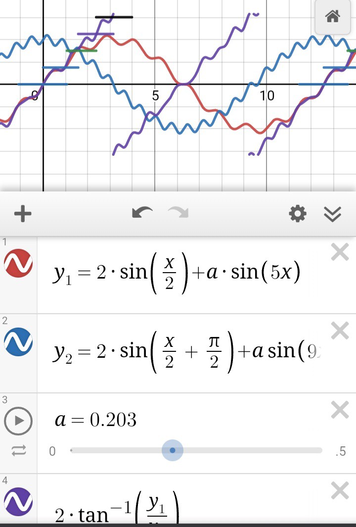
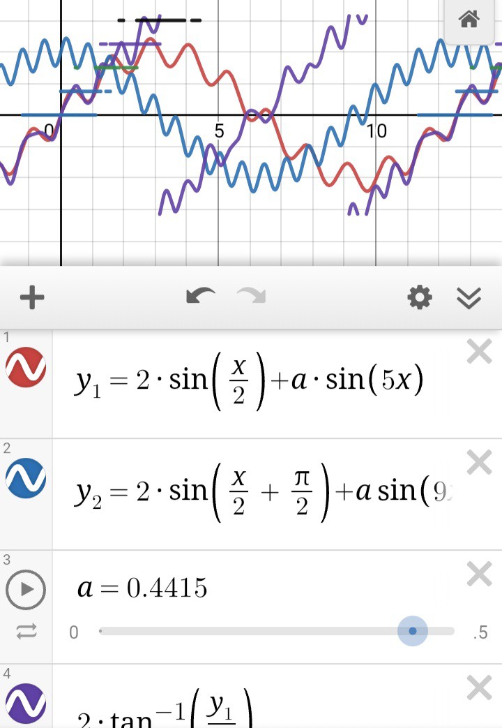
Above is an example of what can result from using arctan when the measurements are off by +-10% (5%?)... This may seem like extremes that are unlikely to be encountered, but bear with me, anyhow.
The overall error at any of the measured positions is, frankly, not even near the step-size of anaQuad. So, at first glance it still seems like arctan is a great choice for higher resolution. And, indeed, depending on your application, it may be.
But consider this: With enough (only 5%?) measurement-error, noise, miscalibration, low battery, etc., arctan can report positions *decreasing* when in fact the motions are increasing. That can be a pretty significant problem if those position measurement/calculations are being fed into a feedback control loop.
Also, as described before, the area near arctan's discontinuities is of great concern, now multiplied. Notice how now the arctan lines overlap, jumping back and forth between roughly -90 and +90 degrees. Such a case would require special attention to avoid potential disaster in a motion-control situation.
Here's another example:
![]()
The stair-steps are anaQuad's output. Again, it has hysteresis...
![]()
Thus It's rather difficult to trigger the misdetection of a reversal where there was none.
The example above is at an extreme 20% error on each measurement, which one might hope never to run into...
On the other hand, we tend to push things beyond their specifications, in these parts... maybe completely unintentionally. And that's easy to do in analog.
For example, in one of my older videos, my analog optical encoder circuit had a strange effect where the outputs' amplitudes decreased somewhat dramatically with motor speed (WHAT?!). Maybe something to do with slew-rates? Rise/fall times? Internal capacitance?
But, say the amplitude, was merely 10% in error... no big deal, eh? But, consider this: The encoder is powered by a single supply voltage... its output is not centered at 0V. And the DC offset /also/ varied somewhat dramatically. So now our measurements with respect to ground, as the ADC reads them, are 20% in error! And to add to it, that was the error on only one of the two WAY-off channels.
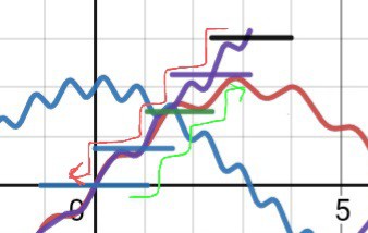
Here's the extreme, where anaQuad may start failing:
![]()
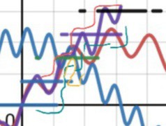
40% error on both channels(!!!) causes weird cases where the hysteresis oscillates back and forth between two measured positions. As shown by the gaps and dashes in the stairsteps.
TBH, I'd never really contemplated what would happen in such a case... and I've never looked at it like this, graphically...
![]()
And it's past friggin midnight, brain-mush is allowed, no?
I *think* the hysteresis still applies, so e.g. the yellow line would *not* occur, falling through the crack to the next step, but then coming right back to the previous through the same crack... hmmm...
This is a very weird and enlightening visualization for me! And it can be animated, too.
...and I've been extremely busy with other things like destroying my progress on #Vintage Z80 palmtop compy hackery (TI-86) which could really help with a much more pressing project than even that, so what am I doing /here?!/
Yeah, guess I'm pretty proud of this one.
-
AnaQuad was Peer Reviewed!
12/06/2021 at 19:41 • 2 commentsThe other day I stumbled on a couple videos from by @Jesse Schoch , wherein he actually implemented anaQuad in a system, gave a pretty thorough overview/discussion, and even expanded on it both in software and by using it in a unique way!
My work was Peer Reviewed!
like... the highest honor for a scientist... and somehow I didn't find out, except by accident, two years later. Believe me, Jesse, I'd've definitely been in contact, had I known.
ON TO THE VIDS:
Jesse doesn't have much of a profile here at HaD, instead he has a wealth of YouTube videos of such projects and concepts.
Back in 2019 (I almost wrote 1999, jeeze I'm old), Jesse dedicated some of his time to implementing anaQuad, and made these vids.
(Apologies; I'd planned to be more thorough in analyzing the vids, themselves, but these days I'm on flakeynet most of the time... I cross my fingers every time I click "Save". Heh!)
Part 1:
Jesse discusses a use-case I'd never considered, a pair of analog hall-effect sensors used to detect the 2mm-spaced alternating poles of a magnetic strip (refrigerator magnet) passing by. AnaQuad is used here to determine the linear motion/position.
I'm not sure I understand his sensor, it has an X and a Z axis, and somehow their readings are at or near 90deg out of phase. However it works, it's a great observation, and a perfect use for anaQuad!
It reminds me of a linear version of 5.25in floppy spindle motors, which have a similar magnet with many alternating poles wrapped around the edge of the (for lack of a better word) flywheel. The hall-effect sensors, there, are three-phase, so offset by 60deg each. I did once modify anaQuad[120] for two of those sensors. Though, the poles were so far apart that resolution was quite low despite the 10+ inches of magnet spinning by.
One observation about this setup is that, if I understand hall-sensors, the waveform output by the sensors would vary in amplitude (and DC-offset?) if these magnets aren't perfectly-aligned with the sensor throughout the entirety of their motion. E.G. if the sensor's path relative to the linear strip isn't /perfectly/ parallel. Also, who knows about the magnetic poles themselves? Surely a fridge-magnet isn't made to tight tolerances. Here, I'm not so much talking about the spacing, that's probably pretty consistent due to the machine that made it. Instead I'm talking about the /strength/ of each pole being consistent across the entire strip. E.G. I would imagine some poles may weaken with various outside factors; being exposed to other magnets on the fridge, etc. Or, also, plausibly, if this is used on an axis of a metal-cutting CNC, the measured flux may vary slightly based on the amount of nearby metal stock.
THIS IS A PERFECT USE FOR anaQuad.
The whole point of its crossover-detection is to reduce the effects of such things on the position-sensing. Imagine one weak pole surrounded by many normal ones, for which the system was calibrated. There, the sine-wave would have a reduced amplitude. And, the surrounding poles might even cause it to have a slight offset from "zero". I won't go into all the details, they've been harped-on in other logs, sufficed to say anaQuad is by-design highly tolerant to such variances.
...
In this first vid, Jesse touches on the concept of merging anaQuad with "sin-cos" postioning. This, honestly, is something I never really considered, as I'd kinda figured the two to be somewhat competitors. Heh!
Part 2:
In the second video, Jesse goes into a bit more detail about how anaQuad works, then shows how to combine it with trigonometry to gain even higher positional-resolution.
The use of trigonometry is something I was /actively/ trying to avoid when developing anaQuad. So, it's difficult for me not to go into all the details of why, and instead see the benefits. I'll try to be open-minded ;)
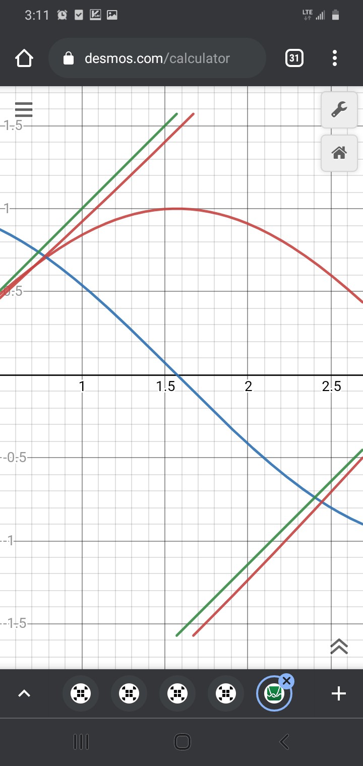
First-off, having seen his graphical visuals, then inspired to run my own calculations, I'm actually quite surprised at how tolerant the use of arctan is to things like DC-offset or amplitude differences. I was imagining a tiny measurement error would cause a huge positional error, and actually that's not particularly true. [Except in a few places, which can be avoided by a simple trick, I'll describe later].
So, after I stopped cringing about trig being compared to anaQuad, I learned something, heh!
I gather that the key concept is that trig can only be used to determine a position within one "step"/cycle... (in fact, only within one half of a cycle!). so... /something/ has to track how many magnetic poles have passed the sensor, and which half of the cycle it's in.
Jesse chose to use anaQuad for this purpose, and I... well... never thought of it like that. A "coarse position and direction tracker". Heh, I was quite proud of how /fine/ I'd gotten its positioning resolution! 16 positions from one slot in an encoder disk!
But, he's spot-on. It /is/ coarse, compared to what /could/ be determined by two sine-waves 90 degrees out of phase. Heck, that's kinda the whole point of trigonometry... sine and cosine make a circle, not an octagon.
So, trig still uses a lot of very slow computations (in floating-point, no less!), in comparison to anaQuad, which uses, as I recall, raw integer measurements from the ADC, a quick jump-table followed by four additions and four comparisons. My guess is that anaQuad should be hundreds of times faster than trig, even on machines with FPUs.
But, again, it's apples and oranges, since trig alone can't keep track of /how many/ cycles, which half-cycle, nor which direction. And, likewise, anaQuad can't even begin to approach trig's resolution.
So, where does this leave us? If resolution is not /highly/ important, anaQuad does a way better job than digital quadrature (I'd better rename anaQuad anaQuadrature, as it's near impossible to search). It's also, similar to digital quadrature, highly immune to external factors. But if you need resolution, trig is the way to go.
Now, some caveats. BOTH are still prone to inaccuracy. And, my guess is, roughly the same amount. Just because anaQuadrature (QuadrAnalogature? AnaloQuad? CrossoverQuadrature?) can detect 16 subpositions within a cycle does /not/ necessarily mean each of those is 1/16th of a cycle apart. In fact, in order to make it fast, some are /definitely/ NOT perfectly evenly-spaced. But that's rather irrelevant, because, again, the fact is these two systems are very much analog, and very much susceptible to many factors.
The fact is, so are /digital/ optical encoders, but it's much harder to see that. In the motion of one slot's passing the sensors, the outputs are in one of four states, so it's easy to imagine that those four states are exactly 1/4 of a slot. But, that's not necessarily true. The brightness of the LED(s?), the sensitivity of the phototransistors, the calibration of their biasing, the thresholds/hysteresis of the Schmitt-trigger/comparator inputs, the tolerance in the sensors' 90degree alignment... all these factors can cause quite a bit of variance in sub-cycle positioning-accuracy.
(I highly recommend looking at the tremendous amount of circuitry used in early Digital Optical Quadrature Encoders from HP... (e.g. from the 7475A plotter. TODO: upload a photo?) they could've simply used a phototransistor, a resistor, and a schmitt trigger for each channel. It's just looking for on and off, rrrriiiggghhhttt? They didn't. Precision and accuracy are very different things! Props to the skill that went into those!)
And I haven't even mentioned external factors like thermal-effects on circuit-components, electrical/RF/60Hz interference, dust, light-seeping...
So, realistically, with any of these systems, pretty much the best accuracy one can /guarantee/ is about +-1/2 of a "slot", as I see it.
Now, obviously, that doesn't mean the subposition information is useless. It just means that one must be conscientious about what the numbers actually mean, and how they can be used. ("Not for life support systems!")
E.G. I don't know if I'd think it wise to use such subposition measurements, even from a digital encoder, to cut threads on a tiny screw. (Nor, and far worse, microsteps of a stepper motor!). But, if I was making a "jog-dial" with high precision at low rotation-speeds and fast-scrolling at higher speeds, trig+anaQuad, may be just the ticket. Frankly, I'm blanking on uses, at the moment, but therein lies another thought...
anaQuad is great for fast-motion... So, e.g. trig may just not be used during such motions, but as the "ticks" start to slow (decelerating near an endpoint), there'd be more processing-time between ticks, which could then be applied to sin-cos for the fine endpoint positioning. Hmmm...
...
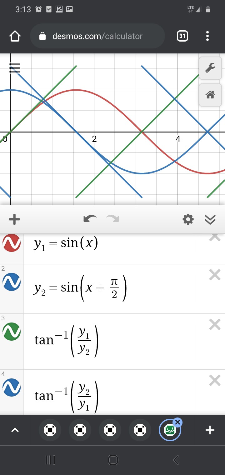
Another thought is about Jesse's "jumps" in the measurements. Arctan, as I recall, outputs from -90deg to 90deg, then jumps back to -90 and repeats.
anaQuad, then, is used to determine /which/ -90 to 90 "hemisphere" the sensors are detecting. Then, the two sensor readings are fed into arctan to get an angle (from -90 to 90deg, which corresponds to /subposition/) within the waveform, i.e. between two opposite magnetic poles.
![]()
Again, /near/ those +90 to -90deg jumps, it's /very/ sensitive to measurement error.
![]()
![]()
You see, even though the arctan method is, for the most part, /surprisingly/ accurate, despite the 0.1 measurement-error, that tiny measurement error can become a /tremendous/ error near arctan's "jump."
Near the jump, using arctan to calculate the subposition, it may be off by as much as a full 180deg! And, yet, again maybe only /very/ briefly, e.g. if this was detected during a CNC axis motion. If this positioning system was used in a feedback loop to *control* the motion, the effect could be quite gnarly (Keep fingers away from moving parts! Always have a big red E-Stop button that actually cuts power to the motor!)
The likelihood of encountering this error may actually be exasperated by the use of anaQuad... but will be a problem in any such system forgetting to take into account special handling of that case.
anaQuad may be able to tell you it's to the left of the jump, but its position-measurement-system definitely differs from the scaling and offset calibration used for the trig calculations. It works based on crossovers between the signals themselves, not measured /values/ relative to the ADCs' ground... so really the two systems are working in two different playing-fields. And, again, I chose that different playing-field for anaQuad /by design/ for the sole purpose of avoiding the ambiguities caused by measurement error. It's similar in concept to differential-signalling, which is often used for noise-immunity.
But, that doesn't mean those two "playing fields" don't overlap... they may be slightly shifted, slightly stretched or shrunk relative to each other within each fraction of a cycle, but they *do* overlap.
...
So, here's the "trick" mentioned earlier....
Make use of anaQuad's multitudes of subpositions.
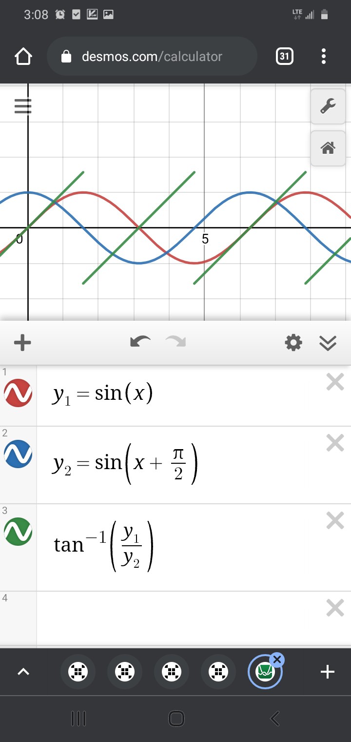
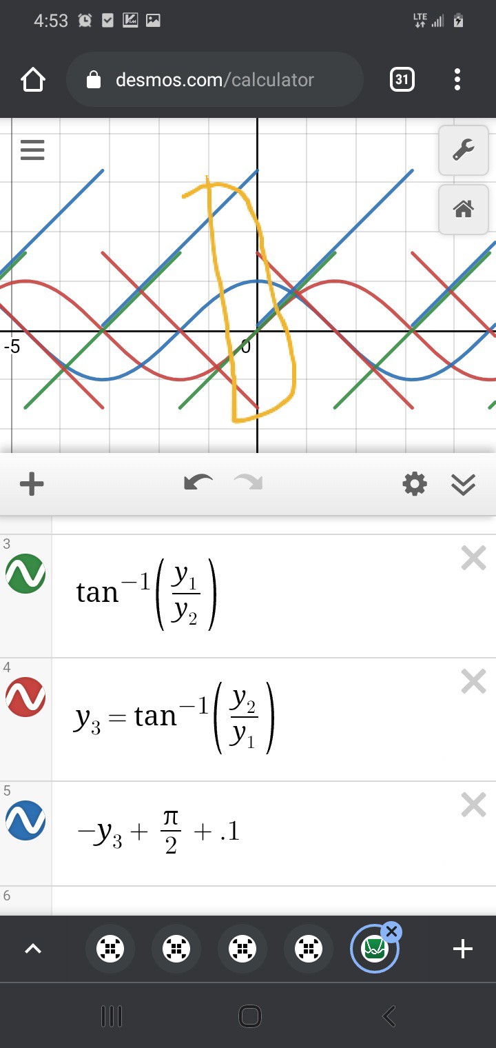
Then, Trig's playing-field can be subdivided such that there are no discontinuities...
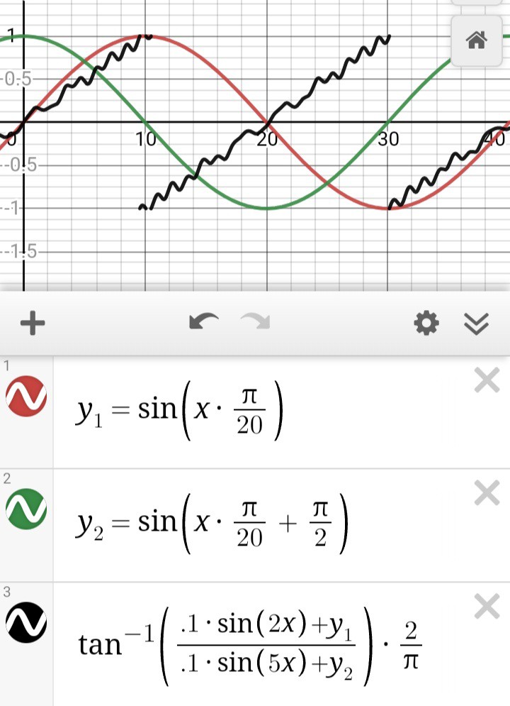
![]()
Wait, what? SOH CAH TOA says tan=opposite/adjacent, and sin<->opposite while cos<->adjacent... it's not soh cah TAO!
But does it really matter, here? The fact is, we have two straight lines which cross each other, then it's only a tiny bit of math to align them:
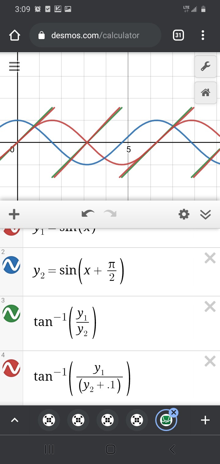
![]()
(I added 0.1 so the overlap of arctan(y1/y2) and the extension from -arctan(y2/y1)+pi/2 would be more visible)
Thus, there is plenty of overlap where /either/ subposition-calculation should determine the same subposition, and it no longer matters how precisely-aligned anaQuad's and Trig's "playing-fields".
Will the results be identical? No. Will there be no "jump?" It might jump a tiny bit when switching between calculations, but it shouldn't introduce gigantic blips of error. I dunno, I've never done it before, you try it!
As I see it, as long as you stay away from eithers' discontinuities, it should be at least as accurate as could've been guaranteed otherwise.
(Upon further thought, it's entirely feasible that upon switching calculation methods, the detected position might *backtrack*, briefly... These are the woes of analog. Again, it might not be wise to feed this into a PID algorithm controlling the speed of a huge motor!)
...
Anyhow, Thank You to Jesse. Seriously, I consider your efforts like Peer Review of my months of scientific research.
---------- more ----------
(HEY HaD, WOULD YOU PLEASE fix the email notification system?! This is not even remotely the first time I stumbled on comments I never received notification of. So... what...? he clicked "follow", then wrote a comment, in the same hour, and you think I care more about a skull than a comment?! Or you expect me to run a 'diff -r' on all my projects/logs/etc, every day?! I would if it were that easy...)
Sorry, folk, this is a years long beef, that was absolutely necessary.
-
PRML
09/23/2018 at 03:09 • 1 commenthmmm....
http://www.pcguide.com/ref/hdd/geom/dataPRML-c.html
So, hard disks now use ADCs and DSPs to detect ones and zeros...
![]()
This looks like a job for ANAQUAD!
Is it too much to ask that two heads on opposite sides of the platter (or maybe two on the same?) stay perfectly-aligned over time and temperatures? 'Cause a rough estimate using anaQuad would easily double, plausibly even quadruple, the capacity despite using twice the physical space...
Thanks @Starhawk for sending me down that path, looking up ZIP drives' encoding-schemes!
-
motor as encoder
09/14/2018 at 03:41 • 1 commentYeah!
Use a BLDC motor as an encoder. Almost *Exactly* as I'd imagined. Combine this with anaQuad, and yer all set!
Note that anaQuad *also* works with two sources that are 120 degrees out of phase, so only two windings of the three in a typical BLDC should be necessary. Also, his technique could probably also be applied to stepper motors.
I dunno how i never seem to come up with this simple concept, myself...
"how can I measure capacitance? Drive with an AC signal, measure phase/magnitude..."
Had to learn this one by example... Simple capacitive touch switches charge the cap, then measure the time it takes to discharge...
Friggin' simple method to apply multiple pushbuttons on a single pin is exactly the same, tie them to different resistor values, charge a cap, measure the discharge time, simple ADC. Bam. I even have a well-developed project based on that (anaButtons, as I recall).
No phase/mag necessary. So, why, then, couldn't I come up with the same for inductors? Duh.
Nice goin' @besenyeim!
I'mma linking this one here so's I can come back to it when the time is right-er.
-
QPSK
11/21/2017 at 21:13 • 0 commentsstumbled upon QPSK (quadrature phase-shift keying) which apparently is the/a method used to transmit data in WiFi...
This looks, actually, quite similar to my earlier rambling thoughts on using anaQuad as a data-transmission method.
Some key (hah) points:
QPSK, since it's tied to RF signals, relies on a phase-shift that's maintained for *numerous* cycles (the carrier wave), whereas anaQuad uses two separate wires, and no carrier frequency, so phase-shifts can be easily detected several times *within* a cycle.
While this may make the two seem quite different, I think both techniques are quite similar in concept, owing most of their differences to their medium.
Also QPSK allows for *two* bits to be transmitted simultaneously... one for each phase in the quadrature signal. Whereas my earlier thoughts for anaQuad only transmits one.
![]()
(QPSK, Wikipedia)
There's good reason. QPSK can allow for signal changes with discrete jumps, each bit-encoding is independent of the previous. The same could be done with anaQuad, plausibly allowing up to 16 or more values (4 bits) to be encoded in each ... thing. (Phase-shift, maybe. Or key?)
My earlier ramblings on anaQuad used as data-transmission explicitly removed the ability for sudden jumps in the signal. Thus, one bit is encoded into each "key" dependent on whether there's a positive phase-change or negative. (Plausibly trinary, considering no-change). Thus, each bit-value's representation (as viewed as a waveform) is entirely dependent on the previous.
Now, I'm not certain I read this correctly, but I think I saw mention that QPSK, or some derivation, is sometimes used similarly.
My reasoning: transmission-lines and slew rates. Sudden changes have slew rates to take into account... transmission lines can *smooth* a sharp edge by the time it reaches a receiver. Also, the receiver itself has slew-rates, the transistors don't switch *immediately*... and... anaQuad pushes those switching-speeds by working with smaller/slower changes (and linear regions).
But... if that somewhat arbitrary limitation was removed, and if the technique was transmitted over a carrier-wave, instead of two wires (and a separate clock? Probably only necessary in the trinary case)... and if it were cut down to only four phases (actually, it seems there are QPSK-derivatives that have more), it would seem the ramblings on using anaQuad for data transmission are... darn-near exactly the same as QPSK, of which I had no prior knowledge.
Yay!
A particularly interesting-to-me learning from QPSK is how the quadrature signals are combined into one... at any instant, except during a phase-change, the signal appears to be nothing but the carrier frequency. So detecting the phase change must require the receiver to have a duplicate of the unshifted carrier-wave running somewhere to compare to... Not dissimilar to how an LVDS receiver uses a PLL to recreate the bit-clock, or how a floppy drive synchronizes an internal clock to clock-pulses on the diskette which are *not* alongside *every* bit.
Not sure how/if to use that with anaQuad... in the two-wire, single-bit, method, clocking is inherent with the bit-phase-transitions. OTOH, it requires two wires.
Mathematically, knowing the two "wire" phases are always quadrature, is it possible to use superposition to combine them on a single wire, still extract the two signals to gain the benefits of "crossover-detection" (noise/source-calibration immunity, mainly) and have inherent-clocking? Sounds like a tall order. But... hmmm....
-
more graphing...
04/14/2017 at 10:36 • 0 commentsUPDATE: Ramblings on LVMDS feasibility/usefulness... why do I do this? See the bottom.
---------
A little more on LVMDS (anaQuad serial-transmission)
![]() explained below...
explained below...-----------------
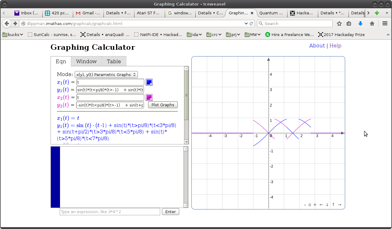
Thought I'd experiment with different graphing-methods... my old go-to online-grapher seems to be down, so here's another:
![]()
The idea was to show only the crossovers, for a half-period of the quadrature-signal... one half sine-wave, which is the passing of one "slot" in the encoder-disk over the photo-sensor (the other half-sine-wave would be passing of the light-blocking material, which I can't figure out the name for, at the moment... maybe "tooth"?). The other half-sine-wave would be basically the same.
So we have two piecewise-equations:
y1(t) = sin(t)       * (t<pi/8)   * (t>-1)
      + sin(t)       * (t>pi/8)   * (t<3*pi/8)
      + sin(t+pi/2)  * (t>3*pi/8) * (t<5*pi/8)
      + sin(t)       * (t>5*pi/8) * (t<7*pi/8)

y2(t) = -sin(t)      * (t<pi/8)   * (t>-1)
      + sin(t+pi/2)  * (t>pi/8)   * (t<3*pi/8)
      + -sin(t+pi/2) * (t>3*pi/8) * (t<5*pi/8)
      + -sin(t+pi/2) * (t>5*pi/8) * (t<7*pi/8)
As it stands, I think it's a bit too funky to visualize, the other graphs were more intuitive for me.
But the ultimate goal, here, (which I'd forgotten until I started writing this, having developed these graphs before the ordeal at home weeks ago) is to make it easier to visualize an encoder (or LVMDS) where the speed/direction changes...
E.G. For an encoder-disk, we'd be talking about say a motor slowing to a stop at a specific position. With a poorly-tuned algorithm, it might oscillate around that point due to overshoot. Then, graphing that using the method shown here would allow for a more ideal simulation where speed/position isn't affected by other factors such as the motor's windings or friction. That'd help for explanation-purposes.
E.G.2. For LVMDS, we'd be talking about transmission of data-bits, wherein a "1" would be represented by a clockwise-rotation of one "step" and a "0" would be represented by a counter-clockwise-rotation of a "step."
The latter-case would be much easier to visualize with this sort of graphing technique... E.G. show the transmission of a data-byte in this anaQuad method. So, maybe I'll get there.
As it stands, this graphing program only allows for two plots... so the color-coordination doesn't really make sense... it doesn't correspond to anything in particular, you have to look at the piecewise functions to see what's happening.
Also, this only demonstrates the simplest implementation of anaQuad, which only doubles the resolution of a typical digital-output optical-encoder.
(If this were compared to two LVDS signals, this method doubles the number of bits that can be transferred within one "eye" or one bit-clock, which would be the blue line crossing over the horizontal axis at 0 and PI).
So, maybe I need to write a program to do the graphing... or at least generate the necessary equations.
We'll see.
#Iterative Motion also could benefit from a GUI, so maybe it makes sense to try to refresh myself on OpenGL...
Oh, I have a relatively simple idea for LVMDS... brb.
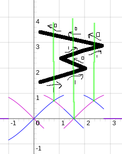
So, here we can see the binary pattern 11011000 transmitted via anaQuad aka LVMDS... not quite as visually-intuitive as I'd prefer, but a start, anyhow.![]()
Also, doesn't show the hysteresis method explained in a previous log, wherein a switch in direction/bit-value would maybe take *two* crossovers to detect, rather than one, just to assure stability, should the electrical-values end-up *near* a crossover, rather than halfway-between.
So, you might be able to see, if there were *two* parallel LVDS signals, their "eyes" would align on the half-sine-wave roughly-outlined in blue. Two data-bits could be transferred simultaneously between 0 and 3.14, one bit on each "signal."
With LVMDS, using two electrically-similar signals as those in LVDS, when those two signals are in quadrature, *four* data-bits can be transferred in the same time, without increasing slew-rates, etc. Something to ponder, anyhow...
---------
So, some pondering, maybe... between the differences of LVDS and LVMDS, at the physics-level... More like rambling...
The frequency-content would be increased... Is that a concern? E.G. the pattern 01010101 sent across LVDS would appear a bit like a sine-wave at a single frequency (half the bit-rate). Whereas, I think, that same pattern over LVMDS would be twice the frequency (but half, or less, amplitude). (right?) (also harder to compare, because it's sent over *two* signals, rather than one).
So, then, there's the question as to whether the frequency-content is a concern... And... we're reaching the limit of my high-speed signal-analysis abilities (especially at this hour and this mind-set). My intuition says that it's less about the frequency-content and more about the slew-rate... that frequency-content analysis of things like the propagation of a signal down a transmission-line is more about a convenient way to look at what's happening... If one were to look at the instantaneous states of things, then consider an instantaneous change, that's more what it's about... (that's how it seems to me).
In which case, especially for this system, maybe we've got to consider not the slew-rate but the slew-rate of the slew-rate? The acceleration-slew?
Another thing to note is that LVDS is designed with proper termination and matched signal-pairs in mind... so, ideally, signal-bounce (reflection) shouldn't be any more a concern for LVMDS than for LVDS. But, we're not in an ideal world... so what effect would reflection have on this system...? On a single differential-pair, probably very little, right? Whatever bounces from one side would bounce in the opposite polarity on the other, and cancel-out at the receiver... right? Hmmm...
Then there's the fact that in this system *two* pairs must work in unison... Reflection on one pair would *not* be coupled into the second, and thus *not* cancelled out... Hmmm...
Then there's jitter and skew... Whereas two LVDS (or even two *parallel*) data-signals could arrive at their destinations, say, 4 picoseconds apart, and still be considered valid, with this system we might need increased precision in that regard... 4ps skew tolerance for LVDS, 2ps for LVMDS. Oy.
What's the effect...? Well, jitter's a bit more difficult, so let's look at skew... That's pretty easy, just imagine that one wire-pair is 2ps longer than the other. I think the rule-of-thumb is 6inches per nanosecond, so 1ps would be 6/1000inches = 0.006in? 6 mils? Kinda tight tolerances for a couple wire-pairs! (And, thus, the reason why we've moved from Parallel ATA and Parallel PCI, and so-forth, to Serial-ATA and PCI-Express, etc.)
That's a pretty big one, right there. Hmmm...
OTOH, maybe, instead of thinking of this as a way to send twice the information at current speeds, instead think of it as a way to send the same amount of information at half the speed?
........
Here's a ponderance... does LVMDS need to have two differential-pairs? Could the same be accomplished by a single pair, where one wire carries the A signal and the other carries B? Since *crossover* is the concern, rather than *value*, maybe coupling these two 90-degree out-of-phase signals *as though* they're differential (and 180deg out of phase) would still gain some of the benefits of a normal differential pair. External electrical-noise coupled into one wire would *also* be coupled into the other wire... So, a common-mode voltage is introduced... and may not matter. (or may...), because, again, we're concerned about *crossovers*.
(Then again, one of the important crossovers to be detected is that of a signal and its inverse, which is part of the reason two differential pairs made sense).
And coupling *between* the signals...? hmmm...
And signal-bounce...? oy...
Anyways, the concept of LVMDS was just a groovy idea I had a while back... based on anaQuad which is nothing to do with anything other than quadrature encoders with analog outputs. No idea whether there's any use for LVMDS in an era where even LVDS is likely somewhat outdated. (Surely your SerialATA cable isn't made with wire-length tolerances of 6mils, right?!)
-
LVMDS revisited...
04/01/2017 at 14:01 • 3 commentsIt's been some time... I don't recall what LVMDS stands for anymore...
LVDS = Low-Voltage Differential-Signalling...
And the M...? Multi?
Some theorizing was presented in previous logs (long ago), here's my attempt at trying to remind myself what I was thinking.
-------------
Anyways, here's anaQuad revisited:
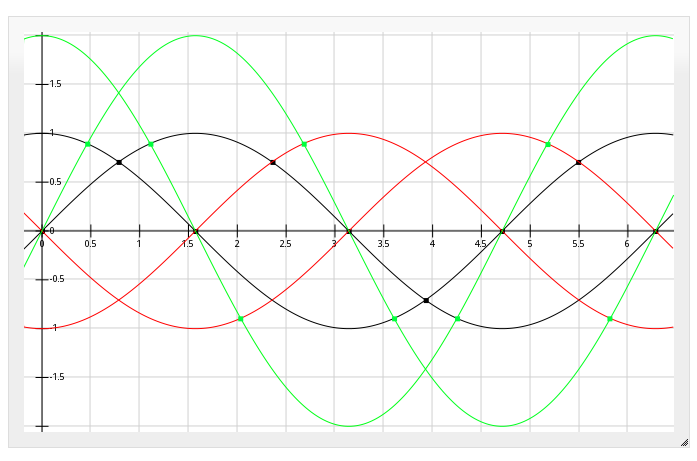
![]()
There are two sine-waves, with a 90-degree phase-shift between 'em. (the two blue lines). These are, e.g. the outputs of the two Quadrature signals of an optical-encoder.
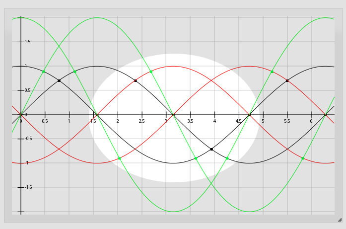
anaQuad, again, increases the resolution of the encoders by looking at crossovers between various multiples of the two input signals. By *inverting* the two input-signals (red), we can detect 8 positions (8 cross-overs) per full-cycle (the blue dots). (This resolution is twice as high as could be detected with digital quadrature signals).
By multiplying the input-signals by ~2, we can double the resolution to 16 positions (the green dots). The resolution can be further-increased by adding more [and more complicated] multiples of the two input-signals, but let's ignore all these for a second and just look at the red and blue waves.
The red and blue waveforms give 8 positions per full cycle. That's 4 positions per half-cycle, using two quadrature signals.
That's for increasing the resolution of a quadrature [optical] encoder with analog output.
-----------------
Imagine, now, if these crossovers represented data-bits in a serial-data-stream...
-------------------------
First some background...
Here's an "eye diagram" for a regular ol' serial-data-stream (e.g. RS-232)
![]()
The waveforms forming the "eye" are numerous bits of a data-stream overlayed atop each other.
When the bit in the center is high, and the two surrounding it are low (#7, above), you'll see a full-sine-wave, starting low on the left, rising to the top of the "eye," and ending low on the right. (If the baud-rate is *really slow* compared to the rise/fall times, it'll look more like a square-wave... as one might expect of a digital signal. For a high-speed serial data-stream, the rise-times and fall-times are almost as long as the high-level and low-level bits, making the waveform more of a sine-wave.)
Similarly, when the bit in the center is low, and the two surrounding it are high (#5), you'll see the same half-sine-wave flipped upside-down.
When three bits are high (#4), you get the top line straight across. Three low, straight across the bottom (#2)... And several other combinations (two bits high, one bit low (#8), and so-forth).
So the eye-diagram shows many bit-patterns overlapping. One might say the center of the "eye" is sampled by the input of the receiving shift-register.
-----------------------
Now, for a *differential* serial data signal, we'd see a similar diagram; for every high-bit on one wire, the other wire sends a simultaneous low bit, and vice-versa. It's symmetrical across the horizontal line bisecting the eye (wee!).
Generally, the receiver might be e.g. a comparator connected to those two opposite-valued signals. When one signal is higher than the other, the output of the comparator is 1, when the other signal is higher, the output is 0.
The bit-value is, essentially, determined at the *time of crossover* between the two input-signals. (Though, technically, most LVDS receivers *sample* the bit-value in the middle of the "eye").
--------------
Now let's go back to anaQuad...
![]()
anaQuad works by looking at the *crossover* of two signals, much like differential-signals (LVDS). But, does-so between not only the input-signal (blue) and its inverse (red), but also a second input-signal and its inverse (the second blue and red pair, respectively)... (as well as multiples thereof (green), which I'm ignoring for now).
By transmitting two signals, in quadrature (the two blue waveforms), at the same frequency as, say, an LVDS signal, we can determine *four* different crossover values (the blue dots) in a single "eye" (half-sine-wave) (ignoring, again, the green 2x signal).
Thus, by paying attention to the *crossovers* (the blue dots), two parallel anaQuad-serial signals could transmit *twice* as much information in the same amount of time as two parallel LVDS signals at the same frequency and same electrical characteristics (which could only transmit one "eye," or one *bit*, per channel, in that time. Two bits, for two two-wire LVDS channels, 4 bits for one four-wire differential-anaQuad-serial channel).
AND, that's only if you look at the original signal and its inverse. Including a 2x multiple would allow for 4x the data-rate. The 2x signals needn't be sent on another wire, or pair thereof, it can in fact be handled by the receiving-end.
------------
This is different than sending an analog value down a wire and reading back the voltage at the receiver. That method would be highly susceptible to external electrical noise, characteristics of the transmitter, the wire, and more.
To measure an analog *voltage*, like that, one typically uses an ADC, and detects whether the voltage is higher than some threshold and lower than another. In the case of LVDS, signals are specified at +/- 0.1V, so to measure 4 analog values in that range would require precision/accuracy of 0.05V. At these levels, any number of factors could cause misread values; from external noise, to resistance in long wires, a 0.05V ripple in the transmitter's supply-voltage, a 0.05V difference between the receiver's ground and the transmitter's.
Instead, since we're looking for *crossovers*, many of those sources of "noise" are removed. When the transmitter's supply-voltage varies dramatically, so may its output-voltages. But both the transmitted signals' voltages change together, so no crossover occurs, and the received signal is otherwise unimpeded. Likewise with variance in the ground-signal. And, since we're talking about transmitting each of the two quadrature signals as separate *differential* pairs, external noise coupled-into one of the wires in a pair is equally coupled into the other wire. Since the two are opposite polarities, the noise is canceled out; no unexpected crossovers are detected.
This has the benefit of differential-signals (similar to "balanced" microphone cables), being highly immune to external electrical interference, as well as significantly lower emissions.
----------
So, the idea, then, is to transmit data-bits with quadrature-encoding. E.G. thinking about an optical-encoder, a "1" bit could be transmitted by rotating the encoder clockwise one "tick", a "0" bit could be transmitted by rotating the encoder counter-clockwise one "tick".
Using the method of detecting crossovers of multiples of the input-values in anaQuad, a single "tick" could be a fraction of a full cycle, requiring less signal-swing (and therefore less time) for each transmitted bit.
---------
There are a couple ways I see this working. One is described above... clock-wise = 1, ccw=0. Another possibility is to keep the value unchanged, in which case ternary is a possibility.
Another consideration is the potential use of crossovers as clock-data. Using the CW=1, CCW=0 method, there will always be a change in the input signal for every bit. This change, then, could be used to transmit a clock-signal simultaneously down the same wire-pair.
A third consideration is the system's ability to retain a "crossover" value, without bouncing *around* it. This is also a consideration in anaQuad, when used with optical-encoders.
Depending on the implementation, the system could be prone to fast-toggling due to values right *near,* and thus oscillating around, a crossover. This can be easily taken care of by embedding a bit of hysteresis in the system. (and has been described in previous log-entries for encoder-handling).
Imagine, again, the CW=1,CCW=0 scenario... say in the previous bit we've travelled "left" by one blue dot (in the diagram), it travelled CCW, so the last bit was 0. Then for the next bit to be read as "1" it would have to travel *two* blue-dots to the right. (Otherwise, it might be sitting *at* the previous blue-dot, and be mistaken). Now we've reduced our bit-rate by ~1/3rd(?)-1/2, but, again, our bit-rate is already twice the equivalent LVDS signals (with, again, the inherent clocking, which usually requires a separate pair), and we can do 2x scaling of the input to double the bit-rate, again... plausibly more.
-
The Idea...
03/30/2017 at 08:48 • 0 commentsThe idea of anaQuad is to use an analog-quadrature source (such as the encoder disks used in an old "ball-mouse") to achieve significantly higher resolution than could be achieved by treating that quadrature-signal digitally. While being relatively immune to analog noise, calibration-error, etc.
It does-so, reliably, by *not* looking at analog *thresholds*, but instead looking at analog *crossovers*. This is well-explained in these pages.
There are several potential sources... Some quadrature-encoders output an analog signal rather than digital (again, e.g. looking at the output of the photo-transistors in a computer's ball-mouse). Some other sources include the hall-effect sensors used in BLDC motors (these are usually 120 degrees out of phase, rather than 90, as in quadrature, but anaQuad120 can handle that).
To *use* this system... Currently it's a software-only approach:
Two analog-to-digital converters are necessary for each encoder.
(Though, theoretically this could be implemented in hardware with a few comparators and op-amps, or maybe even voltage-dividers!)
anaQuad (the software) implements a non-blocking function-call to test the current state of your ADCs and determine the current state (and therefore update the "position")...
In all, it executes only a handful of instructions to detect a change in position, or lack thereof. So as long as it's called often-enough (faster than changes can occur), it puts little strain on your system. The same could be accomplished with a non-blocking digital quadrature-encoder routine in only a few fewer instruction-cycles. This could be called in a timer interrupt or from your main loop (if everything therein is non-blocking, and it loops fast enough).
Interestingly, anaQuad appears capable of "resynchronizing" if a few "steps" go undetected. So, e.g. if your main loop is slowed for some reason during one cycle, and a few anaQuad "steps" are missed, as long as the next few main-loops are faster, the system won't lose any steps! (Again, probably smarter to use a timer interrupt if you're not certain).
-
Home-made anaQuad discs!
04/30/2016 at 09:29 • 5 comments@Logan linked an interesting and easy-to-build encoder-disk method in a comment over at @Norbert Heinz's #Self replicating CNC for 194 (or more) countries project (which has a bunch of ideas for various positioning systems)...
Check out this guy: https://botscene.net/2012/10/18/make-a-low-cost-absolute-encoder/
I'll let the image speak for itself:
So, the current implementation of anaQuad(4x) would give 16 positions with that disk, per revolution. But, that could easily be bumped to 32 via software, and there's no reason the disk has to have only two "poles".
I think something like this would be easier to build than the ol' "slotted" style disks, since slots would require a tiny (or masked) sensing-area, etc.
anaQuad!
Reliably increase your quadrature-encoder's resolution using an ADC (or a bunch of comparators?)
 Eric Hertz


 explained below...

 (
(