
-
HardwareDDC: Reverse-Engineering the DisplayPort AUX Channel
07/07/2026 at 01:50 • 0 commentsWhether you're coming from my Twitter or stumbled across this through a Google search, welcome to my first Hackaday.io article!
My interest in the DisplayPort Auxiliary channel comes from the lack of many MCCS VCP codes like
10and60for brightness and input source on certain monitors. Specifically, the lack of an MCCS implementation through the DisplayPort connections of my Samsung G9—the monitor firmware supports it through HDMI. Two years ago, I built an HDMI DDC accessory as a janky solution to this. However, it was never a "clean" solution I was satisfied with. This started my open-source HardwareDDC project, where I have been exploring better solutions to this problem.Currently, I have been exploring the use of differential transceivers to receive and transmit messages over the DisplayPort AUX channel with the end goal of creating a DisplayPort AUX to HDMI bridge device of sorts. In this article, I'd like to share a quick update on the project, my current challenges, and future plans.
Hardware Design
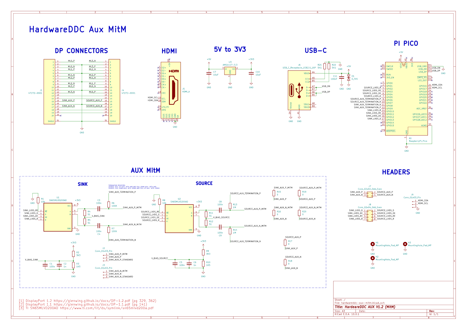
To MitM (Man in the Middle) the AUX channel, I'm using a pair of TI's SN65MLVD200A/AD transceivers. These can act as drivers and receivers—depending on their mode—to read and write messages on the half-duplex AUX channel. This decision was inspired by J5XS' DP-aux emulator. Although it focuses on modifying the EDID through a DP Alt Mode connection, the same basic principles apply to my application.
![]()
The MitM circuit relies on two halves—the sink and source transceiver circuits. The differential pair hardware layout comes from VESA's DisplayPort 1.2 Standard document. Admittedly, my current physics and math skills are lacking to fully understand this circuit from a theoretical level. I understand that termination resistors and their accompanying caps create some form of high-pass filter to allow the square waves to pass, while blocking the DC current.I am also unsure why, in JX5S' reference design, the termination resistors are connected to GPIOs instead of directly pulled up to 3.3V and down to ground. While designing the board, I kept this design decision as if need be, cutting and re-routing the traces to 3.3v and the ground plane is easier than to the MCU pads. While prototyping in MicroPython, I simply defined the GPIO states as:
# source side pins
Pin(6, Pin.OUT).value(1)
Pin(7, Pin.OUT).value(0)

# sink side pins
Pin(8, Pin.OUT).value(0)
Pin(9, Pin.OUT).value(1)
The side which plugs into the user's sink uses 100k terminations to act as a source, and vice versa. On the transceivers' outputs, they provide access to the differential pair as single-ended lines for the microcontroller to interact with. Like in J5XS' design, I left the 10k pull-downs to leave the transceivers in receiver mode by default.
The Auxiliary channel is only one part of the DisplayPort link. There are still the four high-speed video lanes and the HPD pin. Luckily, this project can simply pass-through the video signal like a coupler, as high-speed video debugging is far beyond my capabilities at home. However, I still had to design a board capable of carrying the video signals while minimizing noise. This is where PCBWay, this project's sponsor, and their services have been incredibly useful. Their high-quality manufacturing and assembly are especially important for this project.
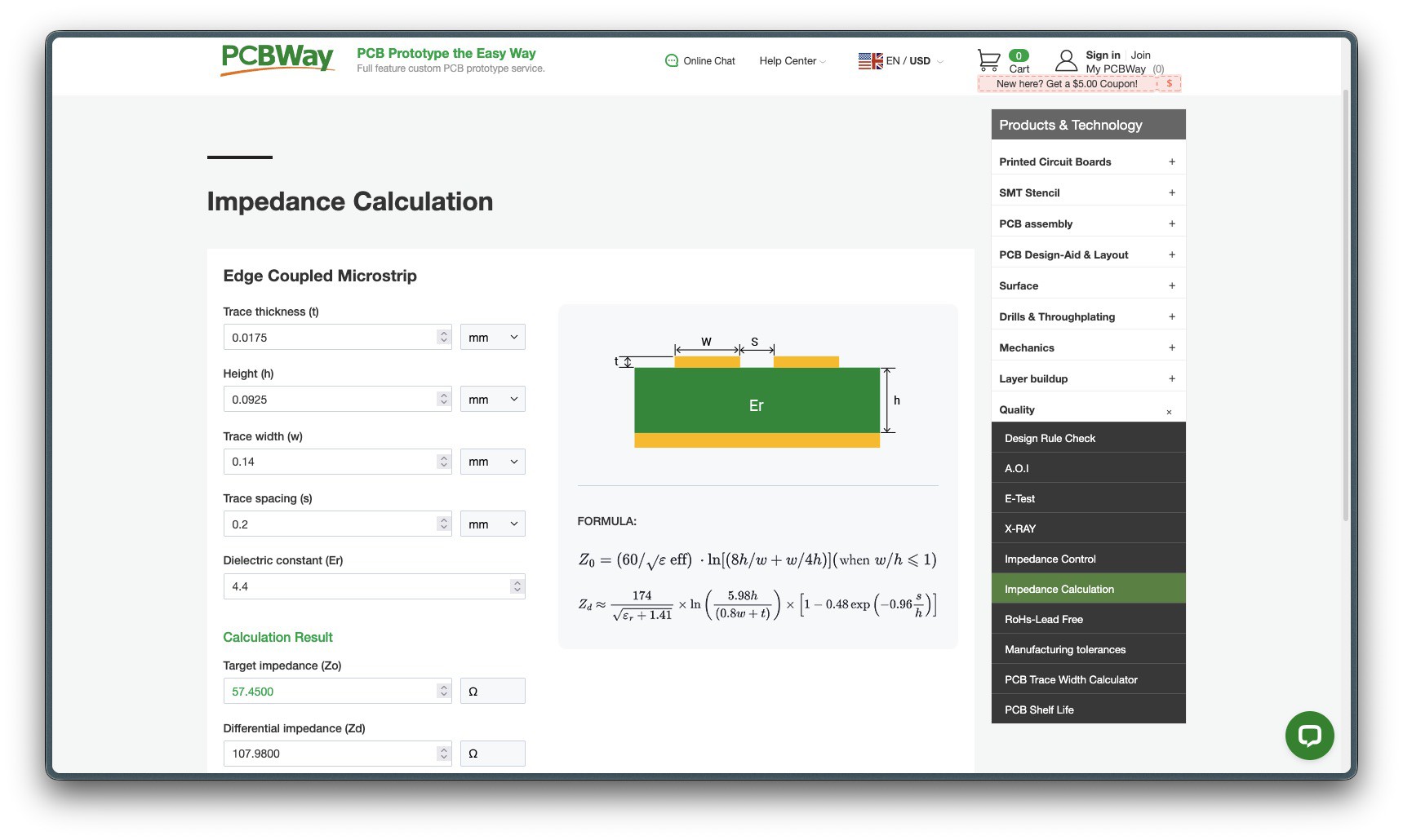
Using PCBWay's IPC 2141 high-frequency impedance calculator, I was able to control the differential impedance of the video lanes to 100 Ω ± 10% based on the selected stackup.
![]()
Read more »
I opted to use PCBWay's 0.6mm 4-layer PCB stackup, as the thin 0.0925 mm dielectric prepreg material keeps the signal layer close to the ground plane. This was my first time working with and designing a very rigid circuit board. Although it was interesting to try it, and useful for my somewhat niche use-case, I might go back to a thicker PCB in the future. The main downsides of using a 0.6mm PCB were: excessive board warping when soldering the MCU dev board if not careful,...
My Pages
Things I've Built
HardwareDDC
A custom PCB to bring support for the DDC control protocol to unsupported monitors. https://github.com/TeaRex-coder/hardwareddc
 Lutetium
 Jared Sanson