Lutetium
-
Hack Chat Transcript, Part 2
03/02/2022 at 21:16 • 0 comments![]()
![]() Well you'd think the functional would not care though.. but yeah so all your post synth work is useless once you go to ASIC and you have to start over
Well you'd think the functional would not care though.. but yeah so all your post synth work is useless once you go to ASIC and you have to start over![]() You know some of the FPGAs had a mux architecture not LUT
You know some of the FPGAs had a mux architecture not LUT![]() And that was like relay logic ...
And that was like relay logic ...![]() Change of topic: Do you have any recommendations for one of the graphical simulators like 'Logisim-evolution' or 'Digital' that can combine digital and analog simulation in the same design? For example, something that could simulate, say, 56-bit shift registers and serial adders and also control the build-up and collapse of inductors' current through the segments of an LED display. I'd like the running simulation to show the contents of the shifters zipping along and the LEDs responding to the inductor field collapse.
Change of topic: Do you have any recommendations for one of the graphical simulators like 'Logisim-evolution' or 'Digital' that can combine digital and analog simulation in the same design? For example, something that could simulate, say, 56-bit shift registers and serial adders and also control the build-up and collapse of inductors' current through the segments of an LED display. I'd like the running simulation to show the contents of the shifters zipping along and the LEDs responding to the inductor field collapse.![]() If you think relay logic is best with say switches in series for AND and in parallel for OR that's not very efficient. Turns out t hey are a mux and you can do anything with Mux
If you think relay logic is best with say switches in series for AND and in parallel for OR that's not very efficient. Turns out t hey are a mux and you can do anything with Mux![]() oops
oopswrong link
![]() Mux relay logic: http://tinyurl.com/h6ynfds
Mux relay logic: http://tinyurl.com/h6ynfds![]() Or to be really perverse: Clever relay XOR: https://tinyurl.com/RelayXOR
Or to be really perverse: Clever relay XOR: https://tinyurl.com/RelayXOR![]() Nice! Something new to absorb!
Nice! Something new to absorb!![]() I wonder if anyone has any favorites to share with Ron. I personally would try to do mixed using Spice. It isn't perfect but I know how to use it and it lets me get as analog as I want
I wonder if anyone has any favorites to share with Ron. I personally would try to do mixed using Spice. It isn't perfect but I know how to use it and it lets me get as analog as I want![]() @Rob Weinstein You are best to write your own. Best of luck with your discussion. I have to go. This sounds like people who have known each other a long time.
@Rob Weinstein You are best to write your own. Best of luck with your discussion. I have to go. This sounds like people who have known each other a long time.![]() But Flastad will do it. Qucs will too
But Flastad will do it. Qucs will too![]() As Richard says, you can write your own too
As Richard says, you can write your own too![]() There are some python libs made for doing custom simulations but I don't know if any of them have analog or not
There are some python libs made for doing custom simulations but I don't know if any of them have analog or not![]() Not my link but this might be useful too
Not my link but this might be useful tooSurvey: https://hackaday.com/2021/06/10/survey-of-simple-logic-simulators/
![]() Just out of curiosity, how many of you have done at least one of the bootcamps?
Just out of curiosity, how many of you have done at least one of the bootcamps?![]() *crickets*
*crickets*![]() There was a 4th one that for now is the last one and wasn't well publicized too: 4th Bootcamp: https://hackaday.io/project/161493-fpga-boot-camp-4-state-machines
There was a 4th one that for now is the last one and wasn't well publicized too: 4th Bootcamp: https://hackaday.io/project/161493-fpga-boot-camp-4-state-machines![]() The state machines are fun because once you figure them out you realize everything is a state machine
The state machines are fun because once you figure them out you realize everything is a state machine![]() in real life I mean
in real life I mean![]() I tend to find my abilities with state machines are severely limited by my own creativity. It's great to see examples of how other people are using them.
I tend to find my abilities with state machines are severely limited by my own creativity. It's great to see examples of how other people are using them.![]() The classic is the traffic light: http://tinyurl.com/ycbpvv5x
The classic is the traffic light: http://tinyurl.com/ycbpvv5x![]()
https://hackaday.com/2015/08/13/becoming-a-state-machine-design-mastermind/
Becoming A State Machine Design Mastermind
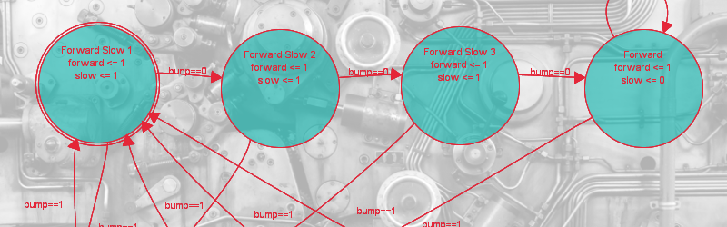
Imagine a robot with an all-around bump sensor. The response to the bump sensor activating depends on the previous state of the robot. If it had been going forward, a bump will send it backwards and vice versa. This robot exhibits behavior that is easy to model as a state machine.
![]() So what have you done with a state machine @Ethan Waldo ?
So what have you done with a state machine @Ethan Waldo ?![]() Just the typical multi-cycle pipeline type stuff. Nothing that serious.
Just the typical multi-cycle pipeline type stuff. Nothing that serious.![]() That's another case where you can describe flip flops or you can describe behavior and let tools generate for you
That's another case where you can describe flip flops or you can describe behavior and let tools generate for you![]() Oh, and AWS Step Functions :P
Oh, and AWS Step Functions :P![]() Typical trade off... you CAN do a better job than the tools in theory but in practice you might not do a better job
Typical trade off... you CAN do a better job than the tools in theory but in practice you might not do a better job![]() One thing I see a lot in industry that I don't see much at hobby level is hardware in the loop simulation
One thing I see a lot in industry that I don't see much at hobby level is hardware in the loop simulation![]() In theory, though, we have the tools. For example, Digital has a way to add things to it from Java. So you could, say, send a PWM signal to real device using a serial port to talk to it.
In theory, though, we have the tools. For example, Digital has a way to add things to it from Java. So you could, say, send a PWM signal to real device using a serial port to talk to it.![]() So maybe you have a PWM-driven heater and a real thermistor and you simulate your controller for PID
So maybe you have a PWM-driven heater and a real thermistor and you simulate your controller for PID![]() Then at the end you build the real thing. We do that all the time using very expensive tools but it seems like it should be possible with tools we have in FOSS
Then at the end you build the real thing. We do that all the time using very expensive tools but it seems like it should be possible with tools we have in FOSS![]() Would be a cool feature for a mixed mode FOSS simulator like QUCs
Would be a cool feature for a mixed mode FOSS simulator like QUCs![]() On the software-side of things I have previously written assembly-level tests that use GDB/MI to actually execute the software on the hardware and see what the registers and memory looks like.
On the software-side of things I have previously written assembly-level tests that use GDB/MI to actually execute the software on the hardware and see what the registers and memory looks like.![]() Maybe @Will Kalman could simulate some student robots like that
Maybe @Will Kalman could simulate some student robots like that![]() :)
:)![]() Yah! running some code on the target and some on the host.
Yah! running some code on the target and some on the host.![]() Speaking of robots that's when you need real mixed mode. Digital, analog, and mechanical. Wind River has a very expensive tool that can do that but I don't know of a FOSS/cheap alternative
Speaking of robots that's when you need real mixed mode. Digital, analog, and mechanical. Wind River has a very expensive tool that can do that but I don't know of a FOSS/cheap alternative![]() Is there some standard data exchange message format to connect simulators for various domains?
Is there some standard data exchange message format to connect simulators for various domains?![]() I am waiting for someone to do VR Spice... simulate your circuit in VR... fly along conductors.... watch current pulse through an inductor
I am waiting for someone to do VR Spice... simulate your circuit in VR... fly along conductors.... watch current pulse through an inductor![]() RFI fields
RFI fields![]() @salec not that I know of... that would be a great idea. In industry there are "shared memory cards" that are very expensive that people use to dump data between simulations like that. You could do something similar of course
@salec not that I know of... that would be a great idea. In industry there are "shared memory cards" that are very expensive that people use to dump data between simulations like that. You could do something similar of course![]() Ohhh virtual miniNEC ... I like that
Ohhh virtual miniNEC ... I like that![]() Something like a stream of time-enumerated event codes
Something like a stream of time-enumerated event codes![]() Look up "reflective memory" - but very pricey
Look up "reflective memory" - but very pricey![]() I'd just be happy if any of these tools were written using modern software testing development practices so all the tribal knowledge of the people who wrote them aren't hidden or lost.
I'd just be happy if any of these tools were written using modern software testing development practices so all the tribal knowledge of the people who wrote them aren't hidden or lost.![]() Meh, it's still VR -- people would end up barfing on their simulations
Meh, it's still VR -- people would end up barfing on their simulations![]() People barf on mine anyway
People barf on mine anyway![]() I simulate my barf
I simulate my barf![]() That's why it's so hard to replace specific EDA tools because no-one knows all the intricate details.
That's why it's so hard to replace specific EDA tools because no-one knows all the intricate details.![]() Not digital per se, but we did some video on LT Spice a while back: https://hackaday.com/2016/02/26/adding-spice-to-your-workbench/
Not digital per se, but we did some video on LT Spice a while back: https://hackaday.com/2016/02/26/adding-spice-to-your-workbench/![]() Vendor lock-in is business strategy
Vendor lock-in is business strategy![]() That's part of the reason, true. Vendor lock in is pretty strong too
That's part of the reason, true. Vendor lock in is pretty strong too![]() lol yep
lol yep![]() even the open ones are very esoteric
even the open ones are very esoteric![]() One of the things we do with the BootCamp is use the open source ICE tools and they are not half bad.
One of the things we do with the BootCamp is use the open source ICE tools and they are not half bad.![]() But post synth simulation and all was lacking last time I dug into them
But post synth simulation and all was lacking last time I dug into them![]() It seems like tools are like standards... everyone loves to make their own
It seems like tools are like standards... everyone loves to make their own![]() NIH is a cancer
NIH is a cancer![]() And too often the WHY of doing something gets lost.
And too often the WHY of doing something gets lost.![]() Like, why did you pick that constant? How did you derive it? Why is it applied in this particular way?
Like, why did you pick that constant? How did you derive it? Why is it applied in this particular way?![]() As an engineer I do suffer from that but as a business guy I try to remember that I should be open. I had a startup company reach out to me once and they had some process with a patent. But the first thing they wanted to do was build a control system for the process because all the ones from Honeywell, Applied Automation, Foxboro, etc couldn't possibly do their process. It was far too special. Needless to say, that blew up in 6 months.
As an engineer I do suffer from that but as a business guy I try to remember that I should be open. I had a startup company reach out to me once and they had some process with a patent. But the first thing they wanted to do was build a control system for the process because all the ones from Honeywell, Applied Automation, Foxboro, etc couldn't possibly do their process. It was far too special. Needless to say, that blew up in 6 months.![]() one of stages has a constant in it that someone we figured had derived it properly like 10 years ago, turns out after asking they'd guessed a value
one of stages has a constant in it that someone we figured had derived it properly like 10 years ago, turns out after asking they'd guessed a value![]() I had advised them to focus on their core competencies but... oh well
I had advised them to focus on their core competencies but... oh well![]() @charliex yes, many end up being approximations based on assumed common use but break down if you're doing something else.
@charliex yes, many end up being approximations based on assumed common use but break down if you're doing something else.![]() @charliex (Mr. Evans?) -- that's funny. I have a habit of making up schedules and putting notes on them that says "This schedule is made up. It is totally wrong. Someone needs to put in a real schedule here" and then I still see the schedule at the end
@charliex (Mr. Evans?) -- that's funny. I have a habit of making up schedules and putting notes on them that says "This schedule is made up. It is totally wrong. Someone needs to put in a real schedule here" and then I still see the schedule at the end![]() yeah its just using good engineering practices, had they commented it was a guess , we'd have calculated it and improved on it no end. its just interesting for NIH and the often said that first day of a new engineering job is throw out the previous folks work,, fun times
yeah its just using good engineering practices, had they commented it was a guess , we'd have calculated it and improved on it no end. its just interesting for NIH and the often said that first day of a new engineering job is throw out the previous folks work,, fun times![]() So Al, what kinds of logic-based projects do you find yourself working on these days?
So Al, what kinds of logic-based projects do you find yourself working on these days?![]() @Al Williams for sure .. some of our engineers refuse to give time schedules because they say its impossible to give accurate ones... the struggle between shipping and r&d :)
@Al Williams for sure .. some of our engineers refuse to give time schedules because they say its impossible to give accurate ones... the struggle between shipping and r&d :)![]() Al, are simulators (and design languages) dealing with, say propagation of errors (like, logic state: "unknown", or "any", or "worst case not what you wanted")?
Al, are simulators (and design languages) dealing with, say propagation of errors (like, logic state: "unknown", or "any", or "worst case not what you wanted")?![]() Hmmm... well in previous day job we did a lot of state machines to handle the docking system that is on the space station (NDSB1). Rad hard FPGAs. Lots of failure analsysis
Hmmm... well in previous day job we did a lot of state machines to handle the docking system that is on the space station (NDSB1). Rad hard FPGAs. Lots of failure analsysis![]() @salec It depends. Simple ones, no. But Verilog, for example, has lots of wire states: 0, 1, X, Z with very specific rules about how X and Z mix with other things
@salec It depends. Simple ones, no. But Verilog, for example, has lots of wire states: 0, 1, X, Z with very specific rules about how X and Z mix with other things![]() There are also drive strengths you can associate
There are also drive strengths you can associate![]() So, you can invent your own algebra, basically?
So, you can invent your own algebra, basically?![]() So a strong 1 can overcome a weak 0 or whatever
So a strong 1 can overcome a weak 0 or whatever![]() i had to leave mid chat and tend to the cnc warming up cycle. but did anyone ever actually realise that asic/fpga combo chip i forget if it was altera/xilinx that was talking about it
i had to leave mid chat and tend to the cnc warming up cycle. but did anyone ever actually realise that asic/fpga combo chip i forget if it was altera/xilinx that was talking about it![]() Well I wouldn't put it that way because they do have very specific rules. But by manipulation I guess you can see it that way.
Well I wouldn't put it that way because they do have very specific rules. But by manipulation I guess you can see it that way.![]() You hear about it all the time, but.... I suspect it would be like Microsemi... they claim you can develop on cheap hardware and move to RTAX but the reality is it isn't much different than developing on Xilinx and going to RTAX. The arch is different enough that it doesn't matter much
You hear about it all the time, but.... I suspect it would be like Microsemi... they claim you can develop on cheap hardware and move to RTAX but the reality is it isn't much different than developing on Xilinx and going to RTAX. The arch is different enough that it doesn't matter much![]() I have been using Digital recently to simulate bit-serial arithmetic as used in the PDP-8/S the CDP1802 amnd early Japanese desktop calculators. It's amazing what can be done with a few gates and some shift registers.
I have been using Digital recently to simulate bit-serial arithmetic as used in the PDP-8/S the CDP1802 amnd early Japanese desktop calculators. It's amazing what can be done with a few gates and some shift registers.![]() Coming up to the top of the hour, so we'll have to let Al get back to work. I just want to say thanks to Al for stopping by today, I really appreciate it. And thanks to everyone for hanging out and asking questions, too.
Coming up to the top of the hour, so we'll have to let Al get back to work. I just want to say thanks to Al for stopping by today, I really appreciate it. And thanks to everyone for hanging out and asking questions, too.![]() thanks al
thanks al![]() yes, thanks for taking the time
yes, thanks for taking the time![]() Thanks!
Thanks!![]() Thanks Al
Thanks Al![]() thanks Al
thanks Al![]() Yeah I love serial ALUs... the oldl Cambridge machines did that. Math at the end of a mercury delay tube
Yeah I love serial ALUs... the oldl Cambridge machines did that. Math at the end of a mercury delay tube![]() Thank you everyone.
Thank you everyone.![]() Thanks Al and everyone who participated
Thanks Al and everyone who participated![]() See you on Hackaday!
See you on Hackaday!![]() Next week we'll be changing things up a bit:
Next week we'll be changing things up a bit:![]()
https://hackaday.io/event/184160-metal-3d-printing-hack-chat
Metal 3D Printing Hack Chat
Printing isn't just for plastic Wednesday, March 9, 2022 12:00 pm PST Local time zone: Hack Chat This event was created on 02/24/2022 and last updated 5 days ago. Join this event's team Agustin Cruz will host the Hack Chat on Wednesday, March 9 at noon Pacific. Time zones got you down?
![]() Thanks all. Transcript coming up shortly.
Thanks all. Transcript coming up shortly.![]() Oh I want a metal 3D printer!!!
Oh I want a metal 3D printer!!!![]() movem.l (sp)+,d4-d7 \n unlk a6 \n rts ; back to work
movem.l (sp)+,d4-d7 \n unlk a6 \n rts ; back to work![]() ooh sintereing
ooh sintereing![]() cool, that will also be an interesting one
cool, that will also be an interesting one -
Hack Chat Transcript, Part 1
03/02/2022 at 21:15 • 0 comments![]() OK, folks, good afternoon/evening/morning to you all. We're ready to kick off the Hack Chat! I'm Dan, I'll be moderating today along with Dusan for Hackaday's own Al Williams!
OK, folks, good afternoon/evening/morning to you all. We're ready to kick off the Hack Chat! I'm Dan, I'll be moderating today along with Dusan for Hackaday's own Al Williams!![]() Hi everyone!
Hi everyone!![]() Hi Al!
Hi Al!![]() Hello
Hello![]() Good to see everyone virutally
Good to see everyone virutally![]() I just saw Al over on the event page chat, asked him to pop over here.
I just saw Al over on the event page chat, asked him to pop over here.There we go -- hi Al!
![]() Hey Al, Dan
Hey Al, Dan![]() I'm in multiple places at once....
I'm in multiple places at once....![]() That sounds like something from the DSM-V...
That sounds like something from the DSM-V...![]() Ah but the more we know about where you are the less we know about your energy state
Ah but the more we know about where you are the less we know about your energy state![]() How's your cat Bil?
How's your cat Bil?![]() Lol... good. Lost the turkey in the cold snap tho...
Lol... good. Lost the turkey in the cold snap tho...![]() Ready to go Dan?
Ready to go Dan?![]() Good to see everyone here...
Good to see everyone here...![]() Ok well let me say a few things about simulation and then we can just kind of freewheel with wherever we want to go with the topic.
Ok well let me say a few things about simulation and then we can just kind of freewheel with wherever we want to go with the topic.![]() Oh yes, by all means -- how about a little about yourself for those who don't know you?
Oh yes, by all means -- how about a little about yourself for those who don't know you?![]() Well, most of you know me from Hackaday and the old among us will remember I was with Dr. Dobb’s Journal and some other magazines back when magazines were made from forest products. Let’s see… I seem to bounce around between things… my undergraduate degree is about 80% EE but I finished with a CS degree (long story). Then I have a Master’s in EE from Columbia (the University, not the country which is spelled different).
Well, most of you know me from Hackaday and the old among us will remember I was with Dr. Dobb’s Journal and some other magazines back when magazines were made from forest products. Let’s see… I seem to bounce around between things… my undergraduate degree is about 80% EE but I finished with a CS degree (long story). Then I have a Master’s in EE from Columbia (the University, not the country which is spelled different).![]() So I’ve done software ranging from low-level assembly to BIOS code. Hardware design from the die level to vacuum tubes to FPGAs. I have designs that have been at the bottom of the ocean and in orbit. I’ve been a ham radio operator for about 45 years or so. I’ve written a bunch of books and a while back I wrote the FPGA bootcamp series that is on hackaday.io.
So I’ve done software ranging from low-level assembly to BIOS code. Hardware design from the die level to vacuum tubes to FPGAs. I have designs that have been at the bottom of the ocean and in orbit. I’ve been a ham radio operator for about 45 years or so. I’ve written a bunch of books and a while back I wrote the FPGA bootcamp series that is on hackaday.io.![]() We actually started out with Bootcamp #1 which uses Verilog, but after talking to some people, I found out that many people really needed to learn just the fundamentals of digital logic. So we did bootcamp #0 which uses online tools to do simulations in your browser. Of course, the Verilog is also a simulation (until it is compiled) and that can be in your browser, too.
We actually started out with Bootcamp #1 which uses Verilog, but after talking to some people, I found out that many people really needed to learn just the fundamentals of digital logic. So we did bootcamp #0 which uses online tools to do simulations in your browser. Of course, the Verilog is also a simulation (until it is compiled) and that can be in your browser, too.![]() It reminds me of when I was in school a very long time ago. We learned drafting with T-squares and pencils. But we had two weeks of “computer aided drafting” where we punched cards like: rectangle(20,20,100,195) and circle(15,30,44). At the time, I thought that was stupid because the future was drawing stuff on the computer.
It reminds me of when I was in school a very long time ago. We learned drafting with T-squares and pencils. But we had two weeks of “computer aided drafting” where we punched cards like: rectangle(20,20,100,195) and circle(15,30,44). At the time, I thought that was stupid because the future was drawing stuff on the computer.![]() But if you look at modern CAD tools, they do let you “code” things so you can have parametric CAD. Some tools like OpenSCAD that’s all you do. If you are making a donut shape, drawing is OK. But if you are making something complex, modeling the relationships is more efficient in the long run. So this also happens with simulations. A lot of people – me included – start learning about Verilog and think that it is stupid because you can just draw schematics. But when you have a CPU with tens of thousands of gates, the schematic entry gets clunky fast. Verilog or VHDL or something like that is the way to go. Consider this 7 segment decoder: http://tinyurl.com/ybqfbk6m
But if you look at modern CAD tools, they do let you “code” things so you can have parametric CAD. Some tools like OpenSCAD that’s all you do. If you are making a donut shape, drawing is OK. But if you are making something complex, modeling the relationships is more efficient in the long run. So this also happens with simulations. A lot of people – me included – start learning about Verilog and think that it is stupid because you can just draw schematics. But when you have a CPU with tens of thousands of gates, the schematic entry gets clunky fast. Verilog or VHDL or something like that is the way to go. Consider this 7 segment decoder: http://tinyurl.com/ybqfbk6mVs this one:
![]() always @(*)
always @(*)case (number)
4'h0: dispoutput <= 7'b1111110; // all segments but center
4'h1: dispoutput <= 7'b0110000; // two segments to form "1"
4'h2: dispoutput <= 7'b1101101; // five segments to form "2"
. . .
![]() Amazing, a Hack Chat with someone that types faster than 1 sentence per 3 minutes!
Amazing, a Hack Chat with someone that types faster than 1 sentence per 3 minutes!![]() So a few random topics we could chat about...
So a few random topics we could chat about... Schematic entry vs HDL.
What doesn’t simulate well?
What does simulate well
Mixed mode simulation
What’s your favorite simulator?
Simulation with a CPU model included (Did you know Falstad can do that? https://hackaday.com/2021/06/11/circuit-vr-arduino-virtually-meets-analog/ – several others, too)
Hardware in the loop simulation
Quantum simulators
Optimization - gates vs speed vs packages vs ???
You tell me…. What do you want to talk about?
![]() You've heard of hunt and peck? Maybe cut and paste lol
You've heard of hunt and peck? Maybe cut and paste lol![]() I "cheat" and use the vendor specific tools such as Altera and Xylinx, what are the open source alteratives?
I "cheat" and use the vendor specific tools such as Altera and Xylinx, what are the open source alteratives?![]() You compiled your notes, professor!
You compiled your notes, professor!![]() How about a "Best choice for beginners" in logic simulators?
How about a "Best choice for beginners" in logic simulators?![]() oh good evening!
oh good evening!![]() I submit that Al is really a simulation (ssshhh... don't tell him)
I submit that Al is really a simulation (ssshhh... don't tell him)![]() Al or AI?
Al or AI?![]() So...
So...![]() Didn't know Falstad had CPU models, sweet!
Didn't know Falstad had CPU models, sweet!![]() I guess the first thing to think about is what you want to accomplish
I guess the first thing to think about is what you want to accomplish![]() I saw recently some apps to pull circuit diagrams from images. Then lots of groups doing SPICE circuit simulations. And lots of videos of beginners (hackers) drawing circuits by hand, and then mumbling half remembered rules for how to calculate basic voltages, currents, couplings and frequencies.
I saw recently some apps to pull circuit diagrams from images. Then lots of groups doing SPICE circuit simulations. And lots of videos of beginners (hackers) drawing circuits by hand, and then mumbling half remembered rules for how to calculate basic voltages, currents, couplings and frequencies.![]() Falstad has the advantage of being no setup. You can even do sort of mixed modes. So for play it isn't bad at all. But serious stuff... maybe not so much.
Falstad has the advantage of being no setup. You can even do sort of mixed modes. So for play it isn't bad at all. But serious stuff... maybe not so much.![]() I use H. Neemann's "Digital" simulator - It's takes over from where LogiSim went down.
I use H. Neemann's "Digital" simulator - It's takes over from where LogiSim went down.https://github.com/hneemann/Digital
![]() I am like Bill. If I'm using a device I will use the vendor tools because they have really good models for it.
I am like Bill. If I'm using a device I will use the vendor tools because they have really good models for it.![]() Falstad could probably get more serious if it were converted to web assembly
Falstad could probably get more serious if it were converted to web assembly![]() Yes I like Digital as well
Yes I like Digital as wellDigital (outputs HDL): https://github.com/hneemann/Digital (has java components, serial port, CPU, etc.)
![]() Falstad probably is fine like it is for what it is
Falstad probably is fine like it is for what it is![]() Great visualization
Great visualization![]() But if you do anything serious schematic entry is ponderous
But if you do anything serious schematic entry is ponderous![]() When I worked for Motorola we used to literally crawl over the schematics for the 68000 on a giant table in our lab
When I worked for Motorola we used to literally crawl over the schematics for the 68000 on a giant table in our lab![]() Honestly would get up on the table and crawl on our hands and knees to read them.
Honestly would get up on the table and crawl on our hands and knees to read them.![]() So for anything serious you really want the HDL type simulations
So for anything serious you really want the HDL type simulations![]() At least you didn't have to draft the transistors by hand....
At least you didn't have to draft the transistors by hand....![]() You had 1s? lol
You had 1s? lol![]() I will say though Bil
I will say though Bil![]() Yes - I heard about the table-crawling when they laid out the 6502 at MOS. Clean socks, with no holes essential....
Yes - I heard about the table-crawling when they laid out the 6502 at MOS. Clean socks, with no holes essential....![]() For quick HDL I really love EDAPlayground and we use it in the bootcamps
For quick HDL I really love EDAPlayground and we use it in the bootcamps![]() EDAPlayground: http://edaplayground.com/
EDAPlayground: http://edaplayground.com/![]() Lol... yes
Lol... yes![]() In browser and access to a lot of commerical-quality and FOSS tools with no setup or install
In browser and access to a lot of commerical-quality and FOSS tools with no setup or install![]() Again, probably not what you want to base the rest of your career on but very cool
Again, probably not what you want to base the rest of your career on but very cool![]() One thing I like about Digital by the way
One thing I like about Digital by the way![]() looks like a good way to develope or test snippets
looks like a good way to develope or test snippets![]() is you can draw schematics and get a truth table or start with a truth table and it will do a schematic. Plus you can export VHDL or Verilog
is you can draw schematics and get a truth table or start with a truth table and it will do a schematic. Plus you can export VHDL or Verilog![]() So that's nice because you can start with a simple schematic / logic diagram and then move to verilog
So that's nice because you can start with a simple schematic / logic diagram and then move to verilog![]() The other nice thing about the vendor tools is they will optimize for the architecture when you build anyway so getting optimal is less important than it used to be... especially since optimal changes depending on what you want
The other nice thing about the vendor tools is they will optimize for the architecture when you build anyway so getting optimal is less important than it used to be... especially since optimal changes depending on what you want![]() Is the exported VHDL any good or do you find you have to re-work it?
Is the exported VHDL any good or do you find you have to re-work it?![]() Al - any thoughts about hosting a Digital bootcamp, to bring schematics and HDL into a common learning resource?
Al - any thoughts about hosting a Digital bootcamp, to bring schematics and HDL into a common learning resource?![]() For example, when I was in school we were taught to get down to all one kind of gate because in those days you probably had one kind of gate you used for everything (discrete transistors). But with SSI like 7400 chips, it was better to use fewer packages
For example, when I was in school we were taught to get down to all one kind of gate because in those days you probably had one kind of gate you used for everything (discrete transistors). But with SSI like 7400 chips, it was better to use fewer packages![]() I don't do much with VHDL these days but the Verilog is good enough. I have not tried anything huge with it though
I don't do much with VHDL these days but the Verilog is good enough. I have not tried anything huge with it though![]() any opinion on cypress' PSoC Creator?
any opinion on cypress' PSoC Creator?![]() I did notice the last release notes from a few weeks ago said that it had some Verilog fixes in it
I did notice the last release notes from a few weeks ago said that it had some Verilog fixes in it![]() I haven't gone all the way thru the boot camps yet, looking to buy some ice40 hw too. At what complexity do the open source tools start to break down?
I haven't gone all the way thru the boot camps yet, looking to buy some ice40 hw too. At what complexity do the open source tools start to break down?![]() Bootcamp for Digital... maybe. I wanted to do some more FPGA bootcamps with development of a UART etc but we were getting increasingly small numbers as the bootcamps wet up in number lol
Bootcamp for Digital... maybe. I wanted to do some more FPGA bootcamps with development of a UART etc but we were getting increasingly small numbers as the bootcamps wet up in number lol![]() i really like psoc creator, its one of the rare tools where a primarily hardware company makes decent software
i really like psoc creator, its one of the rare tools where a primarily hardware company makes decent software![]() Is there any sort of mental break you need to make when using logic simulators to design for FPGA versus when you want to build something from, say, a bunch of 74xx chips?
Is there any sort of mental break you need to make when using logic simulators to design for FPGA versus when you want to build something from, say, a bunch of 74xx chips?![]() PSoC... what a great idea. I love the concept but honestly I haven't used the latest gen of the tool suite. For those of you who don't know
PSoC... what a great idea. I love the concept but honestly I haven't used the latest gen of the tool suite. For those of you who don't know![]() PSoC has a CPU (or several) and some uncommitted logic and analog blocks you can configure ... sort of like an FPGA but at a higher level
PSoC has a CPU (or several) and some uncommitted logic and analog blocks you can configure ... sort of like an FPGA but at a higher level![]() I think there are a few answers to Dan's question
I think there are a few answers to Dan's question![]() Verilog is like a knife... it can chop, carve, or stab
Verilog is like a knife... it can chop, carve, or stab![]() So depending on what you want out of it, it can be very little different or very different
So depending on what you want out of it, it can be very little different or very different![]() As a simulation language you can actually model down to the gate level in Verilog
As a simulation language you can actually model down to the gate level in Verilog![]() I found PSOC usable at least for small stuff.
I found PSOC usable at least for small stuff.![]() And you can naively transcribe gates.... and(q,a1,a2,a3);
And you can naively transcribe gates.... and(q,a1,a2,a3);![]() But the smart money is on telling Verilog what you want and letting the FPGA synthesis figure that out.
But the smart money is on telling Verilog what you want and letting the FPGA synthesis figure that out.![]() So it is like my 7 segment example that I used at the top
So it is like my 7 segment example that I used at the top![]() Logic simulation should be independent of whether it's in an FPGA or a pile of TTL. Timing simulation depends on modeling gate delays and interconnect. This is automatically extracted for FPGAs, but not for board of TTL.
Logic simulation should be independent of whether it's in an FPGA or a pile of TTL. Timing simulation depends on modeling gate delays and interconnect. This is automatically extracted for FPGAs, but not for board of TTL.![]() its good for stuff like ws style programmable led /capacitive touch projects since you can implement the WS driver on the block side and not have to struggle with the tight timing and theyre cheap
its good for stuff like ws style programmable led /capacitive touch projects since you can implement the WS driver on the block side and not have to struggle with the tight timing and theyre cheap![]() You could write all the AND OR gates etc. but why? Just describe it. Phillip makes a good point, although I will disagree slightly. In FPGA design there are really two levels of sim
You could write all the AND OR gates etc. but why? Just describe it. Phillip makes a good point, although I will disagree slightly. In FPGA design there are really two levels of sim![]() Functional is where you make sure you figured out what you want it to do
Functional is where you make sure you figured out what you want it to do![]() But you also do post synthesis simulation to make sure you get timing right and miss race condiditions/metastability and so on
But you also do post synthesis simulation to make sure you get timing right and miss race condiditions/metastability and so on![]() s/condiditions/conditions
s/condiditions/conditions![]() lol
lol![]() So then it does matter and the gate-level sim makes sense there along with vendor models for temperature and clocking
So then it does matter and the gate-level sim makes sense there along with vendor models for temperature and clocking![]() Have you tried moving any of your FPGA designs in to an ASIC ecosystem like Skywater PDK? If so, what were your biggest challenges?
Have you tried moving any of your FPGA designs in to an ASIC ecosystem like Skywater PDK? If so, what were your biggest challenges?![]() Speaking of metastability that is one place where many of the tools you commonly use don't work well is at the rough edges. ... so if you have a 2ps glitch or a time of metastabiity
Speaking of metastability that is one place where many of the tools you commonly use don't work well is at the rough edges. ... so if you have a 2ps glitch or a time of metastabiity![]() I have not done FPGA to ASIC. I've done ASIC professionally where we go straight from sim to ASIC. You really want your simulations correct then because being wrong can cost you your job or your company lol
I have not done FPGA to ASIC. I've done ASIC professionally where we go straight from sim to ASIC. You really want your simulations correct then because being wrong can cost you your job or your company lol![]() Of course, digital is really analog at the bottom and you can simulate with something like LTSpice and it isn't even that hard
Of course, digital is really analog at the bottom and you can simulate with something like LTSpice and it isn't even that hard![]() I am reading these, thinking that you are only describing tools for individuals. Tools that require lots of memorization and practice. Tools that do not scale, and tools that are NOT good at collaboration. When you were crawling the 68000, there was a group. Each person did what they were best at, and not all of them were soldering, or editing circuits on the computer, or ordering parts, or trying to raise funds. You really have not said what you want to make. I know of thousands of global scale problems. You are just talking about tools for part of a problem for one person. What about things that matter? Or problems that cut across many people on Hackaday.io?
I am reading these, thinking that you are only describing tools for individuals. Tools that require lots of memorization and practice. Tools that do not scale, and tools that are NOT good at collaboration. When you were crawling the 68000, there was a group. Each person did what they were best at, and not all of them were soldering, or editing circuits on the computer, or ordering parts, or trying to raise funds. You really have not said what you want to make. I know of thousands of global scale problems. You are just talking about tools for part of a problem for one person. What about things that matter? Or problems that cut across many people on Hackaday.io?![]() That lets you set up horrible simulations with analog issues. And do mixed signal.
That lets you set up horrible simulations with analog issues. And do mixed signal.![]() Altera supposedly had an FPGA to ASIC program but whenever I asked for details no-one from Altera could speak to it.
Altera supposedly had an FPGA to ASIC program but whenever I asked for details no-one from Altera could speak to it.![]() For example: LTSpice can simulate digital:
For example: LTSpice can simulate digital: ![]() Functional sim works best in a single clock environment, and static timing analysis is sufficient for verification of meeting timing. Things get way more messy with two or more independent clock domains. FPGA vendor timing models tend to only do worst case timing, ignoring some of the hazards of a best case situation, (for CMOS: high VDD and low temp)
Functional sim works best in a single clock environment, and static timing analysis is sufficient for verification of meeting timing. Things get way more messy with two or more independent clock domains. FPGA vendor timing models tend to only do worst case timing, ignoring some of the hazards of a best case situation, (for CMOS: high VDD and low temp)![]() The timing between FPGA and ASIC can be a lot different but you'd think it could work pretty well
The timing between FPGA and ASIC can be a lot different but you'd think it could work pretty well![]() there are some of those neat looking asic/fpga combo chips never used one but from what i understand they have the programmable and dedicated layers going on
there are some of those neat looking asic/fpga combo chips never used one but from what i understand they have the programmable and dedicated layers going on![]() We also did a nice set of YouTube videos on LTSpice in general awhile back along with the Circuit VR series
We also did a nice set of YouTube videos on LTSpice in general awhile back along with the Circuit VR series![]() A serious challenge of migrating from FPGA to ASIC is the constraints system and test vectors (or equiv) may not be compatible.
A serious challenge of migrating from FPGA to ASIC is the constraints system and test vectors (or equiv) may not be compatible.![]() Yeah well a lot of ASIC is cell based. So instead of a programmable interconnect you basically just do a single layer of metal on top
Yeah well a lot of ASIC is cell based. So instead of a programmable interconnect you basically just do a single layer of metal on top![]() Yah the contraints in particular. That's one area where it would be nice to have a single ecosystem for both
Yah the contraints in particular. That's one area where it would be nice to have a single ecosystem for both![]() I just asked a chip guy using 7nm ASIC and he said they had 22 layers of metal and 76 masks total, way more than the old days
I just asked a chip guy using 7nm ASIC and he said they had 22 layers of metal and 76 masks total, way more than the old days![]() It is not hard to model digital devices, or systems of any sort - including all the analog elements. And, nowadays, they all depend on software, algorithms, setting goals, and collaboration between people working globally.
It is not hard to model digital devices, or systems of any sort - including all the analog elements. And, nowadays, they all depend on software, algorithms, setting goals, and collaboration between people working globally.![]() Yeah or however many metalization layers you have. All the chips are flipped upside down now too
Yeah or however many metalization layers you have. All the chips are flipped upside down now too![]() also FPGA is constrained by input terms of the LUTs that doesn't necessarily carry over to ASIC.
also FPGA is constrained by input terms of the LUTs that doesn't necessarily carry over to ASIC.![]() or so my memory goes
or so my memory goesAbout Us Contact Hackaday.io Give Feedback Terms of Use Privacy Policy Hackaday API
Logic Simulation Hack Chat with Al Williams
The Truth (Table) Is Out There