-
Hack Chat Transcript, Part 2
03/30/2022 at 20:19 • 0 comments![]()
![]()
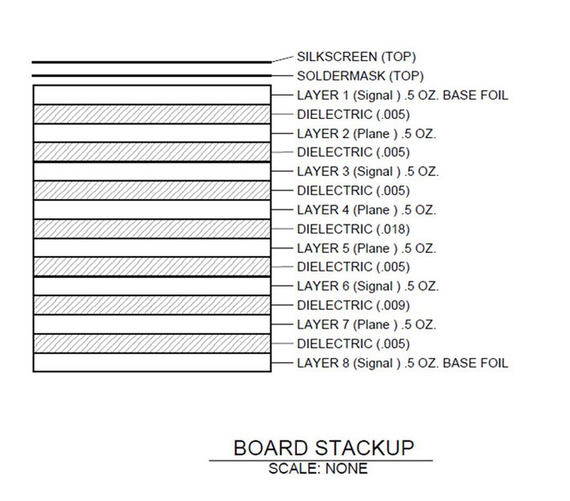
![]() Ok, here is the board stack up
Ok, here is the board stack up![]() OK, thank you very much.
OK, thank you very much.Your links are already helping me!
Do you know any surface mountabe heatsinks manufacturers, too?
So far I used some BGA-heat sinks and mounted them to the PCB with some custom made metal frame.
But that is quite labour intensive and complex. A simpler approach would be appreciated (like those "standard" heatsinks with M3-drill holes and a rail for the mounting clips?
![]()
![]()
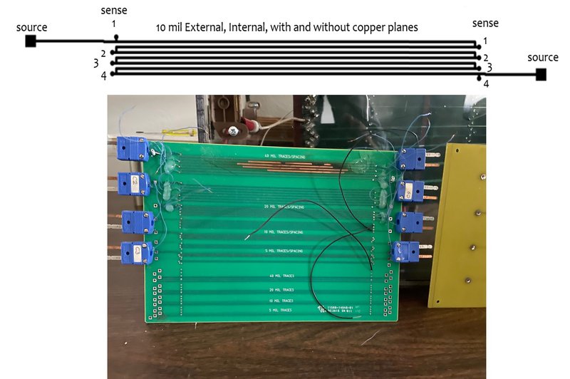
![]() Here is one of the trace configurations on top of the image
Here is one of the trace configurations on top of the image![]() It's a serpentine configuration so we would know that same current is in all the traces
It's a serpentine configuration so we would know that same current is in all the traces![]() Source wires at the beginning and end, along with sense wires at various traces.
Source wires at the beginning and end, along with sense wires at various traces.![]() We had four copper planes in one configuration and the no traces in the other.
We had four copper planes in one configuration and the no traces in the other.![]()
![]()
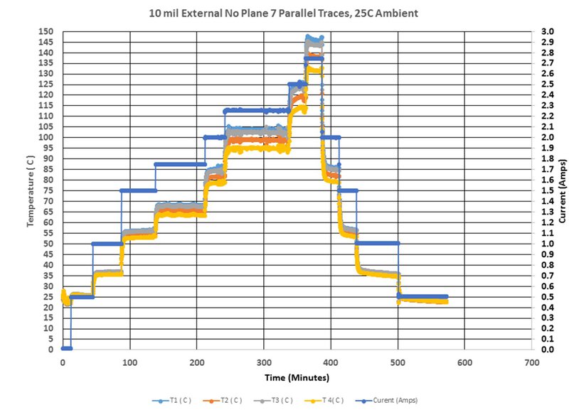
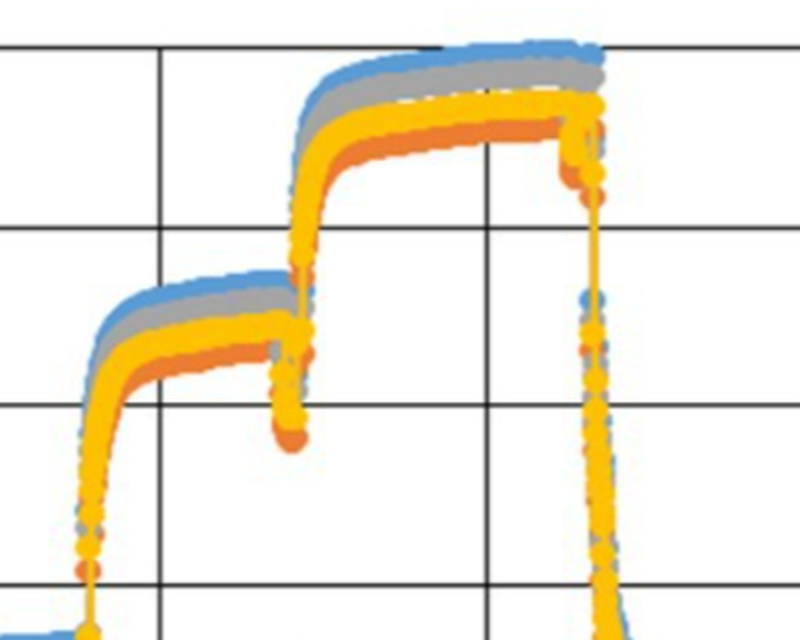
![]() This data has no planes
This data has no planes![]() The board is suspended in air, same as in IPC-2152. We follow the test procedure in IPC-TM-650 2.5.4.1a
The board is suspended in air, same as in IPC-2152. We follow the test procedure in IPC-TM-650 2.5.4.1a![]()
![]()
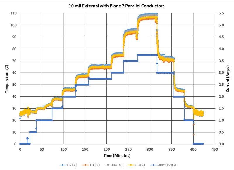
![]() This data is for the board with copper planes.
This data is for the board with copper planes.![]() That's interesting -- almost like there's two equations to fit the transitions to steady state...
That's interesting -- almost like there's two equations to fit the transitions to steady state...![]() Current is on the right side axis and the blue lines are current.
Current is on the right side axis and the blue lines are current.![]() If I'm understanding this correctly, the current still still only being applied through the layer 1 serpentine 10 mil trace but there is an added electrically isolated plane in the PCB for the second chart?
If I'm understanding this correctly, the current still still only being applied through the layer 1 serpentine 10 mil trace but there is an added electrically isolated plane in the PCB for the second chart?![]() Why thermocouples and not thermal imaging?
Why thermocouples and not thermal imaging?![]() I will be adding content back to my website soon at www.thermalman.com. I have already added my papers used to create the charts in IPC-2152.
I will be adding content back to my website soon at www.thermalman.com. I have already added my papers used to create the charts in IPC-2152.![]()
![]()
![]() What's happening -- the transition peaks as I'd expect when the current rises. But then as you let it go for a long period of time, the rate of heat transfer looks almost linear.
What's happening -- the transition peaks as I'd expect when the current rises. But then as you let it go for a long period of time, the rate of heat transfer looks almost linear.![]() No thermocouples
No thermocouples![]() Random thought... could the resistivity-temperature dependence of copper be used to employ the traces themselves as temperature sensors? Could be handy for assessing the inaccessible ones in the internal layers of the boards.
Random thought... could the resistivity-temperature dependence of copper be used to employ the traces themselves as temperature sensors? Could be handy for assessing the inaccessible ones in the internal layers of the boards.![]() The method uses the resistance of the trace.
The method uses the resistance of the trace.![]() ...ah!
...ah!![]() Was confused by the blue connectors on the board.
Was confused by the blue connectors on the board.![]() We're at the end of our normally allotted hour now, but it seems like the discussion is still plenty active. I say keep going if you have the time, Mike.
We're at the end of our normally allotted hour now, but it seems like the discussion is still plenty active. I say keep going if you have the time, Mike.![]() Random thought... could the resistivity-temperature dependence of copper be used to employ the traces themselves as temperature sensors? Could be handy for assessing the inaccessible ones in the internal layers of the boards. Yes, as long as you know the resistance of the trace before heating, then the temperature can be calculated
Random thought... could the resistivity-temperature dependence of copper be used to employ the traces themselves as temperature sensors? Could be handy for assessing the inaccessible ones in the internal layers of the boards. Yes, as long as you know the resistance of the trace before heating, then the temperature can be calculated![]() Hey Mike -- didn't you say you're looking for a company to sponsor your continuation with the work?
Hey Mike -- didn't you say you're looking for a company to sponsor your continuation with the work?![]() I'm looking for a new home for all the software, data, hardware that my company created.
I'm looking for a new home for all the software, data, hardware that my company created.![]() I frequently find myself with very short power traces. Like < 25mm. I am paranoid about thermals, often ending up in ABS enclosures. I'll tend to throw 3oz and wide AF at everything, but i wonder how much I'm over-compensating
I frequently find myself with very short power traces. Like < 25mm. I am paranoid about thermals, often ending up in ABS enclosures. I'll tend to throw 3oz and wide AF at everything, but i wonder how much I'm over-compensating![]() throwing layer after layer of 0.5oz isn't really in the cards for most of the designs I deal with
throwing layer after layer of 0.5oz isn't really in the cards for most of the designs I deal with![]() I join your paranoid feelings about thermals. It was an area of study that I have yet to complete
I join your paranoid feelings about thermals. It was an area of study that I have yet to complete![]() 3oz external 2 layer or 4layer w/ 3oz external / 0.5oz internal is typically all I can get made
3oz external 2 layer or 4layer w/ 3oz external / 0.5oz internal is typically all I can get made![]() "Overcompensating" is an ugly name. Better say "enhanced margins".
"Overcompensating" is an ugly name. Better say "enhanced margins".![]() I used to design up to 24 layers of 2oz, and didn't have a choice
I used to design up to 24 layers of 2oz, and didn't have a choice![]() There's no kill like overkill!
There's no kill like overkill!![]() I wonder if I have a picture of the baord I soldered square copper stock to....
I wonder if I have a picture of the baord I soldered square copper stock to....![]() it had to do 100A
it had to do 100A![]() It was never overkill in the designs I worked on.
It was never overkill in the designs I worked on.![]() 100 A is a bugger
100 A is a bugger![]() I gave up on doing it with just the PCB so I sodlered 10mm square copper bar to the PCB for bus bar
I gave up on doing it with just the PCB so I sodlered 10mm square copper bar to the PCB for bus bar![]() Do you have any good rules of thumbs on the thermal capacity of a PCB? I'm usually unsure on how to handle higher current pulses of say a DC motor starting from standstill.
Do you have any good rules of thumbs on the thermal capacity of a PCB? I'm usually unsure on how to handle higher current pulses of say a DC motor starting from standstill.![]() All about reducing the delta T from Source to sink
All about reducing the delta T from Source to sink![]() what about MCPCB?
what about MCPCB?![]() Here's a somewhat off topic question: I just saw a big Sun server teardown and they had screwed the device PCB to bus bars coming from the power supplies. I always thought you shouldn't run screws through a PCB because the PCB substrate would "flow" overtime and so the screws would never maintain their pressure. Is that just a myth?
Here's a somewhat off topic question: I just saw a big Sun server teardown and they had screwed the device PCB to bus bars coming from the power supplies. I always thought you shouldn't run screws through a PCB because the PCB substrate would "flow" overtime and so the screws would never maintain their pressure. Is that just a myth?![]() It's starting to get easier to get
It's starting to get easier to get![]() I've seen "single layer" MCPCB as well as metal core 2 layer as well as metal prepreg copper prepreg copper 2layer
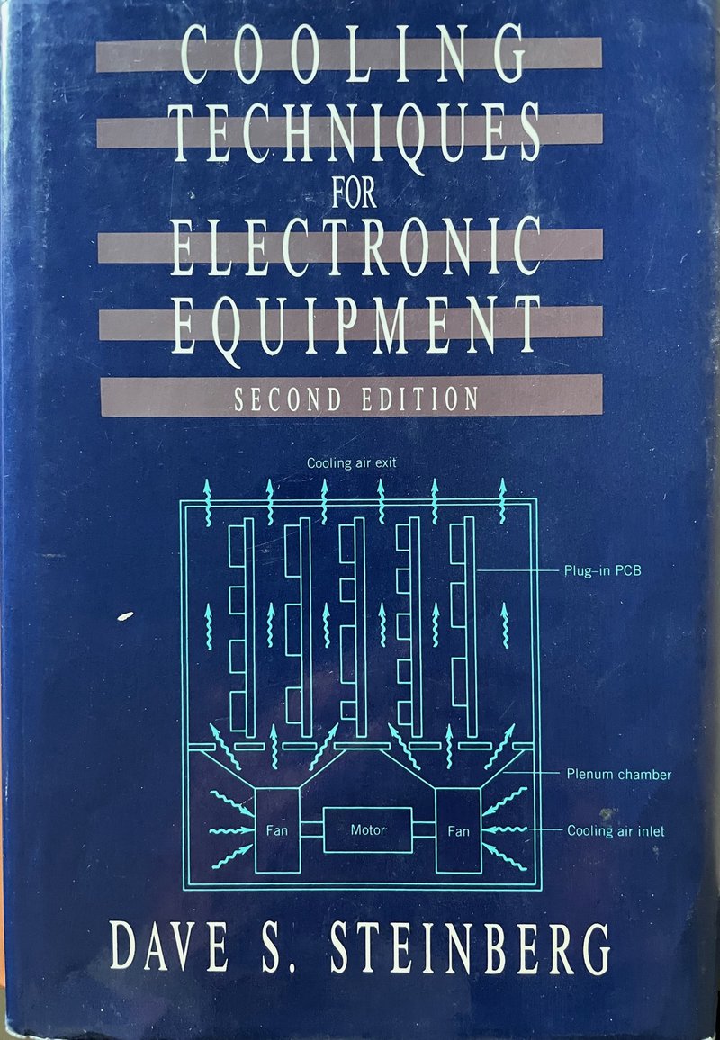
I've seen "single layer" MCPCB as well as metal core 2 layer as well as metal prepreg copper prepreg copper 2layer![]() Do you have any good rules of thumbs on the thermal capacity of a PCB? I'm usually unsure on how to handle higher current pulses of say a DC motor starting from standstill. I assess the pulse using a lumped parameter representation of the physical geometry. It is discussed in the book we showed earlier from Steinberg
Do you have any good rules of thumbs on the thermal capacity of a PCB? I'm usually unsure on how to handle higher current pulses of say a DC motor starting from standstill. I assess the pulse using a lumped parameter representation of the physical geometry. It is discussed in the book we showed earlier from Steinberg![]() @tinfever If it's a concern for you, you can always include spring washers in your design.
@tinfever If it's a concern for you, you can always include spring washers in your design.![]() I'd always wanted to get a manufacturer to connect to the metal layer wth vias for thermal transfer but none of the PCB board houses seem to want to do that
I'd always wanted to get a manufacturer to connect to the metal layer wth vias for thermal transfer but none of the PCB board houses seem to want to do that![]() @Dave Blundell Yeah -- the copper won't bond. It'll fail after a few thermal cycles.
@Dave Blundell Yeah -- the copper won't bond. It'll fail after a few thermal cycles.![]() I was always able to get by with internal copper planes, but I didn't have to deal with 100A in a pcb.
I was always able to get by with internal copper planes, but I didn't have to deal with 100A in a pcb.![]() how much heat transfer can you get into the MC layer without connecting thermal vias?
how much heat transfer can you get into the MC layer without connecting thermal vias?![]() I always wondered about that
I always wondered about that![]() evidently, it's a shitload based on the LED lighting designs I see
evidently, it's a shitload based on the LED lighting designs I see![]() I haven't had any need to do secure screws through a PCB but that myth always kind of worried me. Those issues where "it might work in the short term but could fail in a year" always concern me because it wouldn't show up in normal testing. A spring washer would make sense though.
I haven't had any need to do secure screws through a PCB but that myth always kind of worried me. Those issues where "it might work in the short term but could fail in a year" always concern me because it wouldn't show up in normal testing. A spring washer would make sense though.![]() Anyone designing with Lithium ion batteries? If so, account for the power when they are charging as well as discharging. Lesson learned with Mars Orbiter
Anyone designing with Lithium ion batteries? If so, account for the power when they are charging as well as discharging. Lesson learned with Mars Orbiter![]() Here's the video in case anyone was curious:
Here's the video in case anyone was curious: ![]() @tinfever Take a look at the springs used in your motherboard heat sink application. I guess they're probably not called spring-washers. Those are something else.
@tinfever Take a look at the springs used in your motherboard heat sink application. I guess they're probably not called spring-washers. Those are something else.![]() Great thx
Great thx![]() @tinfever I have been curious about that too. One variant I have seen is to use vias around the mounting hole as that would prevent flow? Not been able to find anything to back that up with actual testing though
@tinfever I have been curious about that too. One variant I have seen is to use vias around the mounting hole as that would prevent flow? Not been able to find anything to back that up with actual testing though![]() Well, I think it's time for me to hit the road. There were a few questions that are difficult to answer in this format. i hope I provided some help to those of you that asked questions
Well, I think it's time for me to hit the road. There were a few questions that are difficult to answer in this format. i hope I provided some help to those of you that asked questions![]() Thank you !!!
Thank you !!!![]() Batteries, yes, do you have a link to the Mars orbiter?
Batteries, yes, do you have a link to the Mars orbiter?![]() Thanks!
Thanks!![]() Thanks Mike!
Thanks Mike!![]() Thanks!
Thanks!![]() Hmm. Yeah, I wonder if those spring screws provide enough pressure to maintain good electrical contact. I bet NASA has written some papers on the exact subject if I bothered to do any research.
Hmm. Yeah, I wonder if those spring screws provide enough pressure to maintain good electrical contact. I bet NASA has written some papers on the exact subject if I bothered to do any research.![]() Thanks!
Thanks!![]() OK, things have slowed down a bit, so I'm going to call time "officially" and say our thanks to Mike for his time today. Feel free to keep the chat going, though -- the Hack Chat is always open.
OK, things have slowed down a bit, so I'm going to call time "officially" and say our thanks to Mike for his time today. Feel free to keep the chat going, though -- the Hack Chat is always open.![]() The lithium batteries were actually on the landers.
The lithium batteries were actually on the landers.![]() Good day all! Cheers!
Good day all! Cheers!![]() And thanks to everyone for all the questions. Great discussion today! I'll pull a transcript in a few minutes in case anyone needs to refer back to something.
And thanks to everyone for all the questions. Great discussion today! I'll pull a transcript in a few minutes in case anyone needs to refer back to something.![]()
https://photos.app.goo.gl/rhG8gccedMz1yHE27
New item by Dave B.
![]() Thanks Mike! And thanks to Mark for helping set this up!
Thanks Mike! And thanks to Mark for helping set this up!![]() that was a prototype from hell
that was a prototype from hell -
Hack Chat Transcript, Part 1
03/30/2022 at 20:19 • 0 comments![]() Hi Mike! Welcome aboard!
Hi Mike! Welcome aboard!![]() Hi Dan, thanks
Hi Dan, thanks![]() We'll get started in just a few minutes
We'll get started in just a few minutes![]() I came in early to see how this all works
I came in early to see how this all works![]() Oh sure -- good idea to see how the interface works.
Oh sure -- good idea to see how the interface works.![]() Hi Mike! Hi Dan!
Hi Mike! Hi Dan!![]() Yes, too easy
Yes, too easy![]() Hi Mark
Hi Mark![]() Hi Mark, welcome back!
Hi Mark, welcome back!![]() Pssh -- miss this? NEVER!!!!
Pssh -- miss this? NEVER!!!!![]() :-)
:-)![]() So -- what's everyone been up to lately?
So -- what's everyone been up to lately?![]() Also Dan -- I don't know if you want to promote it -- Mike just gave a talk with me here:
Also Dan -- I don't know if you want to promote it -- Mike just gave a talk with me here: ![]() Mark, I was going to ask you for that link. So....thanks
Mark, I was going to ask you for that link. So....thanks![]() Well, that's quite the rogue's gallery in the thumbnail...
Well, that's quite the rogue's gallery in the thumbnail...![]() Some say it's the best hour of youtube this year. I say no. It's the best hour this century!
Some say it's the best hour of youtube this year. I say no. It's the best hour this century!![]() (Thos other people also say I'm a bit hyperbolic, whatever that means)
(Thos other people also say I'm a bit hyperbolic, whatever that means)![]() It was a lot of fun though.
It was a lot of fun though.![]() Woohoo! It's go-time!
Woohoo! It's go-time!
Enjoy)![]() (Also Dan, unrelated to Mike, I forgot to share this link with you:
(Also Dan, unrelated to Mike, I forgot to share this link with you: ![]() OK folks, let's get started. Welcome to the Hack Chat, I'm Dan and Dusan and I will be moderating today as we welcome Mike Jouppi to talk about thermal design consideration for our PCBs.
OK folks, let's get started. Welcome to the Hack Chat, I'm Dan and Dusan and I will be moderating today as we welcome Mike Jouppi to talk about thermal design consideration for our PCBs.![]() Thanks Dan
Thanks Dan![]() Hi Mike, welcome! Can you start us off with a little about your background?
Hi Mike, welcome! Can you start us off with a little about your background?![]() Hi Dan & Dusan & Mike!
Hi Dan & Dusan & Mike!![]() Sure, I'm a mechanical engineer that specializes in heat transfer. I'm semi-retired and lately I've been trying to get the word out about IPC-2152
Sure, I'm a mechanical engineer that specializes in heat transfer. I'm semi-retired and lately I've been trying to get the word out about IPC-2152![]() IPC-2152 is an IPC standard for sizing electrical traces in PCBs
IPC-2152 is an IPC standard for sizing electrical traces in PCBs![]() Why Mike, I too love IPC standards. But I find IPC-2221 so burdensome and dated. Tell me more about IPC 2152!
Why Mike, I too love IPC standards. But I find IPC-2221 so burdensome and dated. Tell me more about IPC 2152!![]() I refer to it as a baseline for trace sizing. By that I mean that it represents as basic a configuration as possible.
I refer to it as a baseline for trace sizing. By that I mean that it represents as basic a configuration as possible.![]() Hi everyone!
Hi everyone!![]() Just traces in a pcb. Not copper planes, no mounting and the board is suspended in air or vacuum (for space environments)
Just traces in a pcb. Not copper planes, no mounting and the board is suspended in air or vacuum (for space environments)![]() HoI!
HoI!![]() What amount of current do most engineers need to start worrying about trace heating?
What amount of current do most engineers need to start worrying about trace heating?![]() People think that that is unrealistic for a pcb
People think that that is unrealistic for a pcb![]() The best way to assess trace heating is by the power dissipation of the trace. I^2R
The best way to assess trace heating is by the power dissipation of the trace. I^2R![]() I suppose that changes quite alot based if it placed on an inner or outer layer as well, and the stack-up in general
I suppose that changes quite alot based if it placed on an inner or outer layer as well, and the stack-up in general![]() I think that the standard is unrealistic as well, just to clarify. I think that the copper planes and mounting configurations need to be considered to provide a realistic temperature rise for a given trace size and applied current.
I think that the standard is unrealistic as well, just to clarify. I think that the copper planes and mounting configurations need to be considered to provide a realistic temperature rise for a given trace size and applied current.![]() Inner and outer run very close to the same temp.
Inner and outer run very close to the same temp.![]() Outer run a little hotter in the configuration used for the testing.
Outer run a little hotter in the configuration used for the testing.![]() Is there a way to calculate power dissipation of planes that doesn't require super fancy and expensive simulation software?
Is there a way to calculate power dissipation of planes that doesn't require super fancy and expensive simulation software?![]() Interesting! I've allways been paranoid and made some significant extra margins for the inner layers
Interesting! I've allways been paranoid and made some significant extra margins for the inner layers![]() You can make rough calculations depending on the amount of cut outs and odd geometries
You can make rough calculations depending on the amount of cut outs and odd geometries![]() That's why I'm out talking to people.
That's why I'm out talking to people.![]() Mike, when you say power on pcb tracks, are you refering as the tranverse area right?
Mike, when you say power on pcb tracks, are you refering as the tranverse area right?![]() I created a set of 68 different charts that didn't get published to the public.
I created a set of 68 different charts that didn't get published to the public.![]() Alex -- that's because of some notes in IPC-2221 that were invented by gov't scientists in the 50's. Everyone use to.
Alex -- that's because of some notes in IPC-2221 that were invented by gov't scientists in the 50's. Everyone use to.![]() Did someone say charts?
Did someone say charts?![]() I like charts.
I like charts.![]() In fact, I have a folder on my computer named Charts that lies empty. Sure would be nice if I had some nice charts to put in that folder Mike.
In fact, I have a folder on my computer named Charts that lies empty. Sure would be nice if I had some nice charts to put in that folder Mike.![]() My company developed 68 different charts for sizing traces. We also developed software to use them. It just didn't sell. So we shut down in2004
My company developed 68 different charts for sizing traces. We also developed software to use them. It just didn't sell. So we shut down in2004![]() Hello altogether!
Hello altogether!![]() We incorporated different materials, added copper planes, varied the distance from traces to planes and varied board thickness
We incorporated different materials, added copper planes, varied the distance from traces to planes and varied board thickness![]() The variations are interesting to observe.
The variations are interesting to observe.![]() What do you wish more engineers knew about PCB trace heating?
What do you wish more engineers knew about PCB trace heating?![]() While working with IPC as a volunteer, I chaired the development of IPC-2152. We have a significant list of items to investigate through testing and thermal modeling.
While working with IPC as a volunteer, I chaired the development of IPC-2152. We have a significant list of items to investigate through testing and thermal modeling.![]() Ooo, would love to have joined that research. Have you had any special look at rigid-flex PCBs? I imagine the flex has good thermal isolation
Ooo, would love to have joined that research. Have you had any special look at rigid-flex PCBs? I imagine the flex has good thermal isolation![]() Flex is one that I wanted to do testing on, but we didn't get to it.
Flex is one that I wanted to do testing on, but we didn't get to it.![]() The old IPC-2221 internal chart is good for flex when there aren't multiple layers in the flex
The old IPC-2221 internal chart is good for flex when there aren't multiple layers in the flex![]() I think of flex as a very thin board. The IPC-2152 standard is based on a 0.07inch thick polyimide board
I think of flex as a very thin board. The IPC-2152 standard is based on a 0.07inch thick polyimide board![]() Thanks. I'll have a closer look at these standards!
Thanks. I'll have a closer look at these standards!![]() In your interviews and on your website, you advocate for engineers making their own charts. I assume you mean in the style of the 68 unpublished ones. Can you recommend a way to get started on that method?
In your interviews and on your website, you advocate for engineers making their own charts. I assume you mean in the style of the 68 unpublished ones. Can you recommend a way to get started on that method?![]() That's a bit of a story.
That's a bit of a story.![]() I will try to give a brief outline
I will try to give a brief outline![]() And greetings from Germany.
And greetings from Germany.Thank you for organizing this event and actually I have a question for you.
I am desingning a power electronics PCB and for a full bridge converter I want to use some surface mounted MOSFET which are meant to be cooled from the bottom side of the PCB.
The name of the package in question I couldn't remember (something odd from Infineon), but it is around half the size of a D2PAK package.
The losses that are occuring can be as high as 15 W per MOSFET (that's 60 W in total then).
My questions are:
-how can I design the cooling in general? (Heat sink on the bottom of the PCB)
-where can I find suitable heat sinks and mounting options? Maybe a manufacturer name would be helpful.
-how to design thermal vias properly (under der MOSFET, all around the package,...)?
-general design guidelines
If you could help my I would be very glad!
![]() I will get back to this last question in a minute.
I will get back to this last question in a minute.![]() Creating trace design charts. Start by creating a thermal model of the board represented by IPC-2152. Correlate the model to the charts in IPC-2152 and then expand on the model. All the info for model inputs are in IPC-2152 and the appendix in IPC-2152
Creating trace design charts. Start by creating a thermal model of the board represented by IPC-2152. Correlate the model to the charts in IPC-2152 and then expand on the model. All the info for model inputs are in IPC-2152 and the appendix in IPC-2152![]() Back to the full bridge converter. Are you doing any thermal modeling?
Back to the full bridge converter. Are you doing any thermal modeling?![]() My questions are:
My questions are:-how can I design the cooling in general? (Heat sink on the bottom of the PCB) If the bottom of the PCB is your path, then you will want to assess the temperature difference between the component and the bottom of the board. This is done by calculating the thermal resistance through the PCB. You will create a parallel path using the thermal vias.
![]() Interesting that the standard has all the data. I assumed some lab measurements would be required.
Interesting that the standard has all the data. I assumed some lab measurements would be required.![]() Yes, I do.
Yes, I do.Losses are modelled using the spice models and the parasitic components on the PCB.
The Rth of the MOSFET, TIM and a heat sink (one that is usually meant for BGAs) are known.
Only the Rth of the PCB and the vias are unknown.
In the first tests where I put some thermal vias directly under the exposed pad I realized that the heat transfer is very bad.
The cooling concept was a follows:
MOSFET
PCB including thermal vias
TIM
Heat sink
![]() Interesting that the standard has all the data. I assumed some lab measurements would be required. We used a lab to measure the thermal conductivity in the x, y and z plane for the dielectric materials, as well as the specific heat and density.
Interesting that the standard has all the data. I assumed some lab measurements would be required. We used a lab to measure the thermal conductivity in the x, y and z plane for the dielectric materials, as well as the specific heat and density.![]() Mike -- the standard is behind a paywall -- it's unusual for engineers to see it if they don't belong to a company that subscribes to IPC.
Mike -- the standard is behind a paywall -- it's unusual for engineers to see it if they don't belong to a company that subscribes to IPC.![]() In the first tests where I put some thermal vias directly under the exposed pad I realized that the heat transfer is very bad. Yes and with the amount of power you have you will also have a high temperature rise (delta T)
In the first tests where I put some thermal vias directly under the exposed pad I realized that the heat transfer is very bad. Yes and with the amount of power you have you will also have a high temperature rise (delta T)![]() When people start running 1 or 2 amps and up, then we start to see trace heating that needs to be assessed in a design.
When people start running 1 or 2 amps and up, then we start to see trace heating that needs to be assessed in a design.![]() I also like to talk about parallel conductors and high current pulses.
I also like to talk about parallel conductors and high current pulses.![]() Parallel Conductor Rule:
Parallel Conductor Rule: For groups of similar parallel conductors, if closely spaced, the temperature rise may be found by using an equivalent cross-section and an equivalent current.
The equivalent cross-section is equal to the sum of the cross-section of the parallel conductors, and the equivalent current is the sum of the currents in the conductors.
![]() Hello Mike,
Hello Mike,thanks for answering.
The principals about heat sinks and thermal calculations are nothing new to me.
I would like to learn how to properly design a cooling solution of smd MOSFET.
E.g. which series of heat sinks are on the market (including mounting if possible)?
And how to design the thermal vias properly? (Diamerter, position, amount, ...)
![]() I would like to learn how to properly design a cooling solution of smd MOSFET.
I would like to learn how to properly design a cooling solution of smd MOSFET.E.g. which series of heat sinks are on the market (including mounting if possible)?
And how to design the thermal vias properly? (Diamerter, position, amount, ...) I always kept a spreadsheet with calculations for sizing thermal vias. The spreadsheet is handy. Copper planes on the first few layers near your component do a lot for spreading the heat
![]() How much of a role does the board substrate play in thermal characteristics? Seems like the FR4 (or whatever) could act as a heatsink to draw heat away from traces. Or is that a naive way to look at it?
How much of a role does the board substrate play in thermal characteristics? Seems like the FR4 (or whatever) could act as a heatsink to draw heat away from traces. Or is that a naive way to look at it?![]() There is an old rule of looking at 45 degree spreading from the component down through the board. The copper planes increase the area for helping to conduct through the board and allow more thermal vias to help
There is an old rule of looking at 45 degree spreading from the component down through the board. The copper planes increase the area for helping to conduct through the board and allow more thermal vias to help![]() Copper is 1000 times more conductive than the dielectric
Copper is 1000 times more conductive than the dielectric![]() The board doesn't help much. We measured the thermal conductivity in each axis to get the best data possible for our thermal modeling.
The board doesn't help much. We measured the thermal conductivity in each axis to get the best data possible for our thermal modeling.![]() When I first studied high current pulses, I used to use the melting temperature of copper to assess fusing.
When I first studied high current pulses, I used to use the melting temperature of copper to assess fusing.![]() I use a method called a lumped parameter representation of the physical geometry. I was able to do some testing and later had my testing validated by Johannes Adam and work he did with Doug Brooks.
I use a method called a lumped parameter representation of the physical geometry. I was able to do some testing and later had my testing validated by Johannes Adam and work he did with Doug Brooks.![]() It turns out that 600C is the threshold for looking at high current pulses. At 600C you will see thermal run away and fusing.
It turns out that 600C is the threshold for looking at high current pulses. At 600C you will see thermal run away and fusing.![]() Is it even possible to transfer that much (15-60W) thermal energy from the top of a PCB to the bottom? It feels like there would be a finite limit on Watts per board area.
Is it even possible to transfer that much (15-60W) thermal energy from the top of a PCB to the bottom? It feels like there would be a finite limit on Watts per board area.![]() What will be the best way to learn to model thermal PCBs? Thx
What will be the best way to learn to model thermal PCBs? Thx![]() Is it even possible to transfer that much (15-60W) thermal energy from the top of a PCB to the bottom? It feels like there would be a finite limit on Watts per board area. That's a good question. I've had similar problems. It gets exotic. You have to assess a path to the sink. With that much power, small resistance create large delta T's.
Is it even possible to transfer that much (15-60W) thermal energy from the top of a PCB to the bottom? It feels like there would be a finite limit on Watts per board area. That's a good question. I've had similar problems. It gets exotic. You have to assess a path to the sink. With that much power, small resistance create large delta T's.![]() it all starts with all the energy into the system and assess how you can get the energy out.
it all starts with all the energy into the system and assess how you can get the energy out.![]() What about differential CTE and board failures with high delta-T's Mike?
What about differential CTE and board failures with high delta-T's Mike?![]() Exactly, Mike.
Exactly, Mike.But can you tell me how you designed the themal vias in such cases?
Maybe there are any application notes?
![]() I never liked the stress side and spent most of my time on the thermal side.
I never liked the stress side and spent most of my time on the thermal side.![]() https://www.ti.com/lit/slma002 TI has this one.
https://www.ti.com/lit/slma002 TI has this one.![]() The standard for thermal pad patterns is IPC-7093 I believe.
The standard for thermal pad patterns is IPC-7093 I believe.![]() Epoxy fill is expensive (and usually pointless.) You're better asking for thicker wall plating. But you have to create a solder dam or the via cavities will flood with solder and you'll get voiding between the land pad and the part pad.
Epoxy fill is expensive (and usually pointless.) You're better asking for thicker wall plating. But you have to create a solder dam or the via cavities will flood with solder and you'll get voiding between the land pad and the part pad.![]() But can you tell me how you designed the themal vias in such cases? It is a parallel thermal path. Calculate the thermal resistance of one thermal via. Calculate how many you will need to get the delta T that you need through the board and then assess if it is feasible.
But can you tell me how you designed the themal vias in such cases? It is a parallel thermal path. Calculate the thermal resistance of one thermal via. Calculate how many you will need to get the delta T that you need through the board and then assess if it is feasible.![]() You can create different drill sizes and have the vias plated up with copper to get the cross sectional area you need to achieve the thermal resistance that you are trying to get. Do all this in a spreadsheet
You can create different drill sizes and have the vias plated up with copper to get the cross sectional area you need to achieve the thermal resistance that you are trying to get. Do all this in a spreadsheet![]() With the power that you are considering, it is best to use some thermal modeling tools to assess your design.
With the power that you are considering, it is best to use some thermal modeling tools to assess your design.![]() What will be the best way to learn to model thermal PCBs? Thx Classes in heat transfer
What will be the best way to learn to model thermal PCBs? Thx Classes in heat transfer![]()
![]()
![]() This is a good book for hand cranks
This is a good book for hand cranks![]()
https://www.abebooks.com/9780471524519/Cooling-Techniques-Electronic-Equipment-2nd-0471524514/plp
9780471524519: Cooling Techniques for Electronic Equipment, 2nd Edition - AbeBooks - Steinberg: 0471524514
Details infallible techniques for designing electronic hardware to withstand severe thermal environments. Using both SI and English units throughout, it presents methods for the development of various reliable electronic systems without the need of high-speed computers.
![]() Anyone interested in some trace heating data from a parallel conducting test we did?
Anyone interested in some trace heating data from a parallel conducting test we did?![]() I would absolutely be interested.
I would absolutely be interested.![]() YES!
YES!![]()
 Lutetium
