 Dave Collins
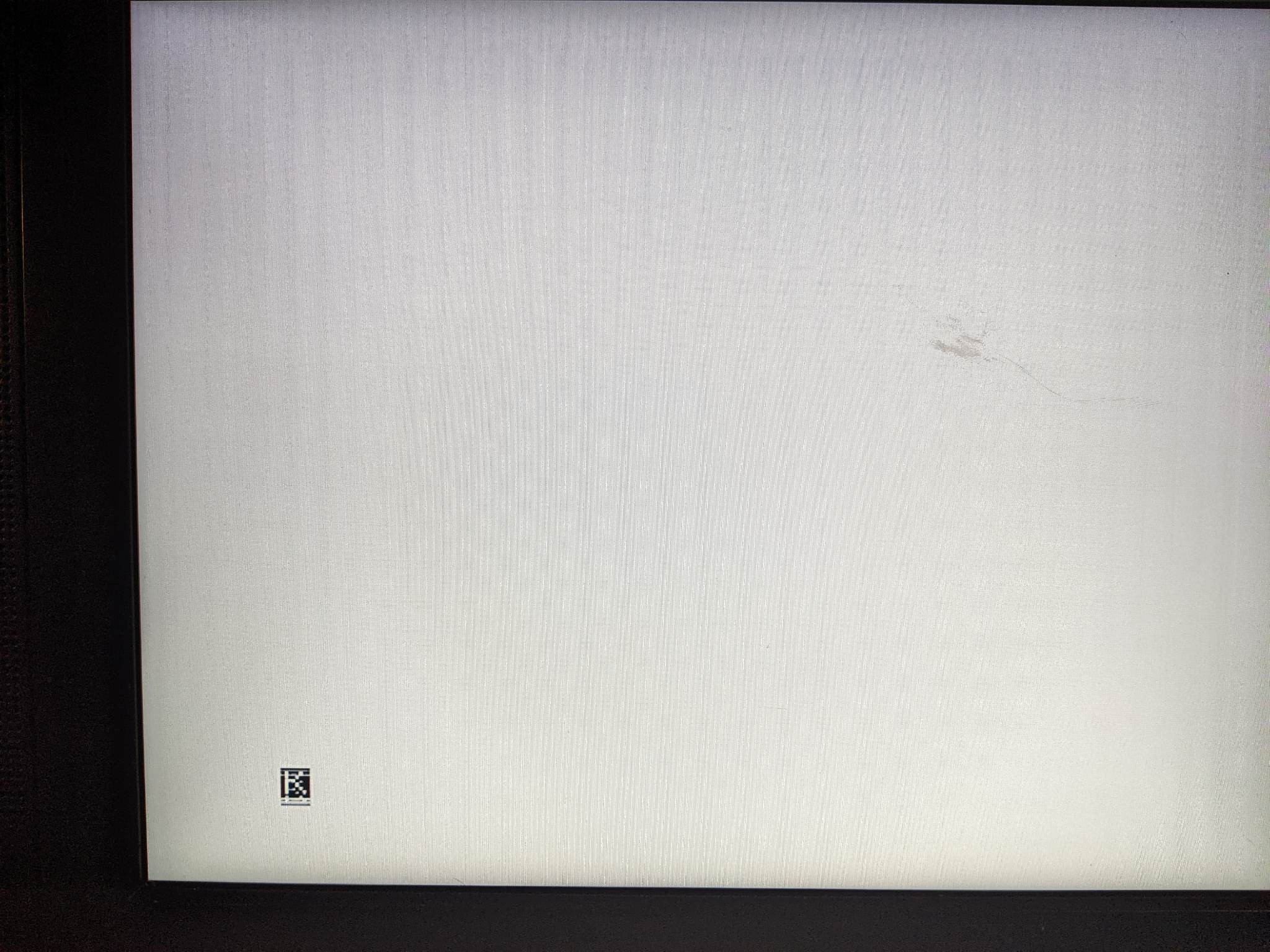
Success! well sort of:
Initial false start. I was able to get a 'K' Prompt to load, but with astoundingly bad ghosting. I went to work checking for the common things. --- ingress from cracked traces or loose connections the usual analog-ish type stuff. In Broadband when we have ghosting in a analog signal, we look for an impedance mismatch base band is not much different.
I checked with the scope and found there was very irregular reflections which got slightly better if I probed the reference clock circuit. I figured this was more about the probes veritable capacitor of a few pF then the huge resistor in my x10 probe. Checking for other obvious signs of a crack I decided to just slide the ULA from its socket slightly and re-seat it. This had little to no effect and I ran into some more issues with resets and starting up properly.
Checked a few more things and found that the !OE line on the ram upgrade was not connected but bent out. A quick google search found the specific mod being done here and I sorted the issue by grounding the pin (in this design only one of the enable lines are needed).
I flipped the board over and checked the pads under the ULA and found a few of them were not soldered very solidly so i re flowed a few of the pads. When i pulled back my iron from the third pad I started to uncover the problem --- the pins were coming loose from the socket above!

I removed the big chips from the board and found that most of the larger chip sockets were completely corroded . I don't have very sophisticated de soldering equipment, a manual pump, temperature controlled soldering iron and a good amount of solder wick. The easiest way of going about careful chip removal in a board this old without an automatic de soldering pump is to cut up the sockets and pull them out 2 or 3 pins at a time. This sounds time consuming but its actually quite efficient and probably only took about 15 minutes to remove all 3 sockets. Since I had the mask ROM and the CPU out, I replaced both with newer parts -- CMOS Z80, and a 16K 120nS EPROM. The Mod for the EPROM was fairly trivial, I just bent out the pins that did not line up and manually routed them which amounts to only 3 of the pins.
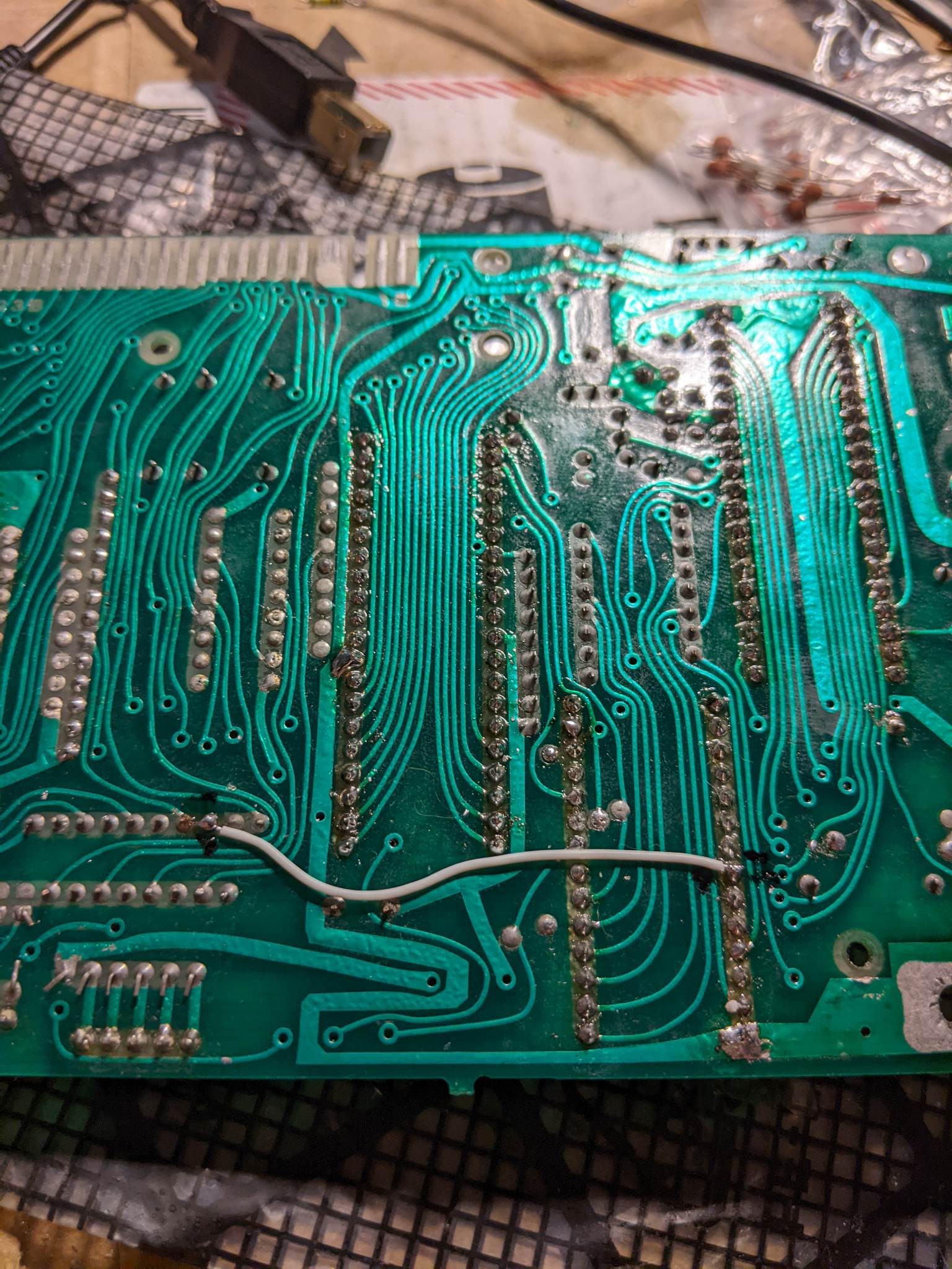
 I ended up cracking a trace replacing this socket for the Mask ROM. I ran a wire on the back side to the next point in the design (on of the bus arbitration resistors):
 After I replaced the broken trace I plugged everything back in, plugged in the computer and immediately ... got no picture... Its a 40 year old machine with aging corroded parts I have to be realistic and so I half expected this. This lead me down a number of avenues, I wound up toning out all of the traces using the schematics, and replacing the RAM expansion after discovering it was causing some of the lower address lines to stay low.
SO... The saga continues.
I went back to basics, Started probing some of the lines coming from the ULA, determined I was getting a sync signal but it looked very noisy:
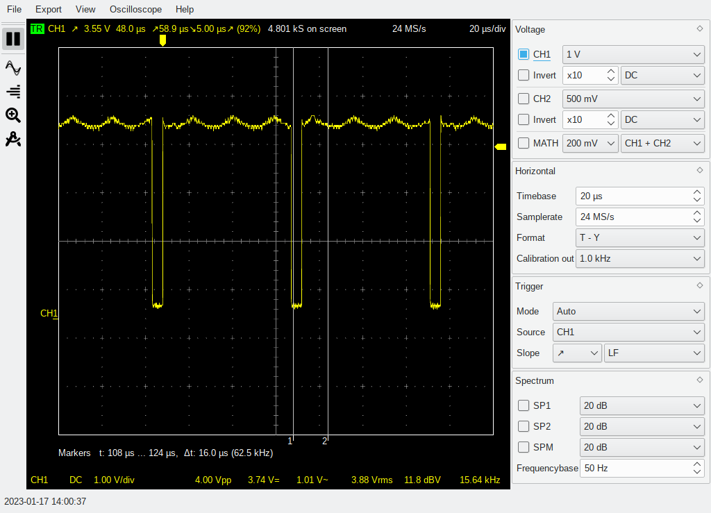
So the amplitude should not shift like that, and though you cant tell because this is a still it does, roll across the top as well. - - it should be fairly flat. The line data is there (you can't see it in this screenshot.) and I pulled the time base out so you can see it. This looks like an oscillation, the clock for the CPU, the line clock and the sync are all made inside the ULA.
A new approach (Lets remove the DC Offset):
We have a sync but its very bad, so bad in fact that the TV can not see it as it just looks like DC voltage levels -- the best way to trouble shoot the issue at this point is to try to get the TV to display "something". I pulled the back porch mod; and built the simplest composite mod (from byte delight ~ image is linked:

after constructing the mod as designed - I added a 300uF or so electrolytic capacitor (to remove the DC offset). This worked and we can see further evidence of 'regular oscillation':
These 'hum bars' which roll through the picture, are common when low frequency interference is injected into an otherwise normal picture. So to tackle this problem and isolate the ULA as the trouble we first have to rule out other sources of oscillation.
Normally with oscillation, we are looking for an active device (the ULA, 74series logic that is made to oscillate, a broken crystal etc...). But in old electronics we can find some of the capacitors particularly older electrolytic ones that are noisy.
I went through more of the passives, on the board looking for issues. I found a few of the ceramic caps particularly on the input section of the board which were completely open, and one resistor which was also open. I also was able to verify the main oscillator is working normally, and I replaced the small in line capacitor that feeds into the ULA and is the source of the clocks.
I have to continue looking at the other passives, particularly the electrolytic caps. But I think I will order a modern ULA replacement, at this point it just makes sense since most of the main chips are replaced, and to really do the restoration justice I should try to get as much of the heat from the case as I can. additionally the video output on the New ULA can be set to generate the back porch, as well as output a normal 75 ohm impedance signal which can be piped directly into the TV without any levels conversion or buffering.
Discussions
Become a Hackaday.io Member
Create an account to leave a comment. Already have an account? Log In.
Enjoying the story. Thanks for taking the time to write it up.
Are you sure? yes | no
Thanks for taking the time to read :) I appreciate it.
Are you sure? yes | no