 pcbmaster
If you have spent any time designing or repairing electronic circuits, you have probably encountered a 10k resistor.
It appears in schematics almost casually: a 10 kΩ pull-up here, a voltage divider there, perhaps another one connected to a capacitor, transistor, sensor, or microcontroller pin. Because 10k is so common, it is easy to treat it as a generic resistor value rather than a component with specific electrical consequences.
That is exactly where things get interesting.
A 10k resistor is not simply “a resistor with a convenient value.” Depending on where it is placed, it can determine whether a digital input has a stable logic state, whether an RC circuit responds quickly enough, how much current flows through a sensor interface, or how much power a voltage divider wastes.
This guide looks at 10k resistors from a practical circuit-design perspective: what the value actually means, why engineers use it so often, where it works well, and where choosing 10k can create problems.
What Does a 10k Resistor Actually Mean?
The notation 10k means 10 kilohms, or:
10kΩ = 10,000Ω
Resistance describes how strongly a component opposes electrical current. According to Ohm's law:
V = I × R
Therefore:
I = V / R
For example, if 5 V is applied across a 10kΩ resistor:
I = 5 V / 10,000 Ω = 0.5 mA
At 3.3 V:
I = 3.3 V / 10,000 Ω = 0.33 mA
Those currents are relatively small, which is one major reason 10kΩ is useful in low-power electronic circuits.
The resistor's power dissipation can also be calculated:
P = V² / R
With 5 V across a 10kΩ resistor:
P = 25 / 10,000 = 2.5 mW
So a typical 1/8 W or 1/4 W resistor has plenty of power-handling margin in this situation.
However, the voltage across the resistor matters. A 10k resistor connected directly across a much higher voltage can dissipate substantially more power.
Why Is 10kΩ Such a Common Resistor Value?
There is no special physical property that makes exactly 10kΩ the “correct” resistance for electronics.
Its popularity comes from a useful balance.
A resistor that is too low in value can consume unnecessary current. A resistor that is too high can become more susceptible to leakage currents, noise, interference, and input impedance effects.
10kΩ often sits comfortably between those extremes.
That makes it particularly useful for circuits where the resistor primarily establishes a voltage or logic state rather than carrying significant load current.
Common applications include:
- Digital input pull-ups
- Digital input pull-downs
- Voltage dividers
- Reset circuits
- Transistor bias networks
- Sensor interfaces
- RC timing networks
- Analog input conditioning
- Button circuits
- Configuration straps
Because the same value works in many different situations, 10k resistors have become something of a standard toolbox component.
10k Pull-Up Resistors: One of the Most Common Uses
One of the first places to encounter a 10k resistor is a pull-up resistor.
Suppose a microcontroller input can either be connected to ground by a switch or left disconnected.
Without a pull-up, the input can become floating when the switch is open. A floating CMOS input may interpret electrical noise as unpredictable logic transitions.
Adding a 10k resistor between the input and the positive supply solves the problem.
VCC
|
[10k]
|
+------ MCU input
|
Switch
|
GND
When the switch is open, the 10k resistor pulls the input toward VCC.
When the switch closes, the input is connected to ground.
The resistor therefore creates a predictable default state without continuously forcing a large current through the switch.
For a 5 V circuit, closing the switch produces approximately:
I = 5 V / 10kΩ = 0.5 mA
That is small enough for many ordinary digital interfaces.
Why not use 1kΩ?
You could.
However, the lower resistance would cause more current to flow when the switch pulls the node low.
At 5 V:
- 1kΩ → 5 mA
- 4.7kΩ → about 1.06 mA
- 10kΩ → 0.5 mA
- 100kΩ → 0.05 mA
Consequently, 10kΩ provides a useful compromise between current consumption and a reasonably strong pull-up.
10k Pull-Downs Work the Same Way
The same principle applies in reverse.
A 10k pull-down resistor connects a signal to ground while allowing another device to drive the signal high.
MCU / Signal
|
+------ Input
|
[10k]
|
GND
When the signal source is disconnected or high-impedance, the input defaults to LOW instead of floating.
This is particularly useful for:
- Enable pins
- Mode-selection inputs
- Reset-related signals
- MOSFET gates
- Microcontroller configuration pins
- Push-button inputs
Still, 10k should not be treated as a universal pull-up or pull-down value. Interface speed, leakage current, capacitance, noise environment, and power budget can all change the ideal resistance.
Using 10k Resistors in Voltage Dividers
Another classic application is the voltage divider.
Two 10k resistors create a simple divider:
VIN
|
[10k]
|
+------ VOUT
|
[10k]
|
GND
The output voltage is:
Vₒᵤₜ = Vᵢₙ × R₂ / (R₁ + R₂)
Because both resistors have the same value:
Vₒᵤₜ = Vᵢₙ / 2
Therefore:
- 5 V input → 2.5 V output
- 3.3 V input → 1.65 V output
- 12 V input → 6 V output
This is useful for signal scaling, reference generation, and measuring voltages with a microcontroller ADC.
However, there is an important engineering detail here: a voltage divider is not an ideal voltage source.
The two 10k resistors have a Thevenin equivalent resistance of:
10k || 10k = 5kΩ
If the ADC or connected circuit draws significant current, the output voltage will shift.
That means a 10k/10k divider is excellent for many high-impedance inputs, but it may be inappropriate when the divider output must drive a low-impedance load.
10k Resistors and RC Timing
A 10k resistor becomes even more interesting when combined with a capacitor.
The basic RC time constant is:
τ = R × C
For a 10k resistor and a 100 nF capacitor:
τ = 10,000 × 100 nF = 1 ms
Increase the capacitor to 1 µF:
τ = 10 ms
Now the same resistor can participate in a circuit that filters noise, delays a signal, shapes a pulse, or smooths an analog voltage.
This is why 10k frequently appears next to capacitors on schematics.
For example:
Signal
|
[10k]
|
+------ Output
|
[100nF]
|
GND
The resistor and capacitor form a simple low-pass filter.
Its approximate cutoff frequency is:
fc = 1 / (2πRC)
For 10kΩ and 100 nF:
fc ≈ 159 Hz
Consequently, the value of a seemingly ordinary 10k resistor can directly influence the dynamic behavior of the circuit.
The Hidden Trade-Off: Resistance vs. Capacitance
There is an important relationship between resistor value and signal behavior.
A higher resistance combined with parasitic capacitance produces a larger RC time constant.
Consider a digital input with only 100 pF of effective capacitance.
With 10kΩ:
τ = 10k × 100 pF = 1 µs
With 100kΩ:
τ = 10 µs
With 1MΩ:
τ = 100 µs
For a slow button signal, that difference may be irrelevant.
For a fast digital interface, however, it can become significant.
Therefore, while 10k is often a good default, it should not automatically be used on high-speed signals.
10k Resistors in Transistor Circuits
A 10k resistor can also be used for transistor biasing or as a base/gate-related resistor, although the correct value depends heavily on the specific transistor and circuit topology.
For a BJT, resistor values influence base current.
For a MOSFET, a 10k resistor is frequently used as a gate pull-down or pull-up.
For example, a MOSFET gate can be connected to ground through 10kΩ so that the transistor remains OFF when the controlling microcontroller pin is floating during startup.
This is particularly useful because microcontrollers do not always have their GPIO pins in their final operating state immediately after power is applied.
A resistor can establish the desired default state before firmware takes control.
What Does “10k” Mean on the Resistor Itself?
Depending on the resistor package and marking system, you may not literally see 10k printed on the component.
Through-hole resistors
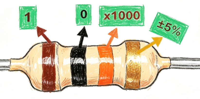
A traditional axial resistor may use a color code.
For a 10kΩ resistor, the common four-band code is:
Brown – Black – Orange – Gold
That represents:
- Brown = 1
- Black = 0
- Orange = ×1,000
- Gold = ±5%
So:
10 × 1,000 = 10,000Ω
The gold band indicates a ±5% tolerance.
Surface-mount resistors
Small SMD resistors commonly use numerical markings.
A typical three-digit marking for 10kΩ is:
103
The first two digits are 10, while the third digit indicates three zeros:
10 × 10³ = 10,000Ω
Larger or more precise components can use different marking systems, and very small components may have no marking at all.
That last point is worth remembering when debugging a PCB: never identify an unmarked SMD resistor purely from its appearance.
Is a 10k Resistor Exactly 10,000Ω?
Usually, no.
Real resistors have tolerance.
A 10kΩ resistor with ±5% tolerance can theoretically measure between:
9.5kΩ and 10.5kΩ
A ±1% resistor has a narrower range:
9.9kΩ to 10.1kΩ
For many digital pull-up applications, this difference is insignificant.
For precision analog circuits, however, tolerance can directly affect circuit accuracy.
There are additional parameters to consider as well:
- Temperature coefficient
- Voltage coefficient
- Long-term stability
- Noise
- Power rating
- Maximum working voltage
- Package characteristics
Consequently, “10k” describes the nominal resistance, not the entire electrical behavior of the component.
Why 10k Is Not Always the Right Choice
The most dangerous habit in circuit design is choosing a resistor value simply because it is familiar.
Imagine a designer using 10kΩ as a pull-up on a high-speed digital bus.
The resistor may work perfectly in a prototype running at low speed. However, once the circuit operates at a higher data rate, the combination of pull-up resistance and bus capacitance may produce edges that are too slow.
At the other extreme, using 10kΩ in a battery-powered voltage divider that remains permanently connected can create unnecessary continuous current consumption.
For a 12 V supply and two 10k resistors:
I = 12 V / 20kΩ = 0.6 mA
That may sound insignificant.
However, a battery-powered product running continuously can accumulate substantial energy consumption over time.
Increasing the resistor values could reduce this current, although doing so introduces other trade-offs involving leakage, noise, ADC acquisition time, and measurement stability.
The correct resistor value is therefore a system-level design decision, not a popularity contest.
Choosing Between 1k, 4.7k, 10k, and 100k
A quick comparison is useful:
Resistance | Typical Character | Common Applications |
1kΩ | Stronger pull, higher current | LED current limiting, signal conditioning |
4.7kΩ | Relatively strong pull-up | Digital interfaces, bus pull-ups |
10kΩ | General-purpose compromise | Pull-ups, pull-downs, dividers, RC circuits |
100kΩ | Low current, weaker pull | High-impedance sensing, configuration inputs |
These are not strict application rules.
For example, an LED circuit requires a current-limiting resistor based on LED forward voltage and desired current, so 1kΩ is not automatically the right choice.
Likewise, communication interfaces such as I²C require pull-up values based on bus capacitance, voltage, speed, and device specifications.
The lesson is simple: start with the electrical requirement, then select the resistor value.
Designing Around 10k Resistors on a PCB
Once a circuit moves from a schematic to a physical PCB, resistor selection is only part of the job.
Placement can matter too.
For a pull-up on a sensitive digital signal, keeping the resistor reasonably close to the relevant input can reduce the length of the high-impedance node.
For an RC filter, the resistor and capacitor should generally be placed according to the signal path and noise-control objective rather than randomly positioned on the board.
For analog voltage dividers, the trace between the divider and ADC input should be considered carefully, especially when the divider has relatively high impedance.
PCB layout also introduces parasitic capacitance and inductance. Therefore, a circuit that looks perfect mathematically can behave somewhat differently after routing.
During production, component value, tolerance, package, placement, solderability, and inspection requirements also become part of the engineering equation.
For projects moving from prototype into production, PCBMASTER can support PCB and PCBA manufacturing while these component and layout decisions are translated into a manufacturable board.
How to Check a 10k Resistor With a Multimeter
When troubleshooting hardware, measuring the resistor directly is straightforward—but there is a catch.
First, power down the circuit.
Then measure the resistance with a multimeter.
A healthy nominal 10kΩ resistor may show something such as:
9.9kΩ, 10.0kΩ, or 10.1kΩ
depending on tolerance and meter accuracy.
However, measuring a resistor while it is still connected to a circuit can produce misleading results because other components may create parallel current paths.
For example, a 10k resistor measured in-circuit might appear to be only 4.7kΩ or another unexpected value.
That does not necessarily mean the resistor is defective.
If the measurement matters, isolate at least one side of the resistor from the surrounding circuit.
10k Resistors Are Simple—But Their Effects Are Not
The popularity of the 10k resistor comes from its versatility.
It is low enough to provide a reasonably strong bias in many circuits, yet high enough to avoid excessive current in typical logic applications. It also combines naturally with capacitors to create useful RC networks and works well in many voltage-divider configurations.
More importantly, 10kΩ is a useful reminder of a broader engineering principle:
A component's value only makes sense in the context of the circuit around it.
A 10k pull-up, a 10k voltage-divider resistor, and a 10k resistor in an RC filter all have the same nominal resistance—but they perform completely different jobs.
So the next time you see “10k” on a schematic, don't just read it as a component value. Ask what electrical function that resistance is creating.
Is it establishing a default logic state?
Is it limiting current?
Is it setting an analog voltage?
Is it defining an RC time constant?
Is it controlling transistor bias?
And finally, does 10k still make sense once voltage, current, capacitance, leakage, tolerance, noise, power consumption, and PCB implementation are taken into account?
That is where a seemingly ordinary resistor becomes an actual engineering decision.
Discussions
Become a Hackaday.io Member
Create an account to leave a comment. Already have an account? Log In.